

Page 1
Operational Data
Housing
INSTALLATION, OPERATION AND
MAINTENANCE INSTRUCTIONS
LEHL1 LED HAZARDOUS LOCATION
LIGHTING FIXTURES
1. Operate this fixture at its rated voltage. Do not install where the marked operating temperature exceeds
the ignition temperature of the hazardous atmospheres. See fixture label for data.
2. This fixture is intended to be connected to a properly installed and grounded UL listed junction box.
Heavy-duty anodized die cast aluminum
Long lasting and durable powder coat finish
Over-voltage, and over-heat protection
Exposed fasteners with quality stainless stee
Excellent anti-corrosive property
WARNING!
1. TO PREVENT THE RISK OF ELECTRICAL SHOCK DEACTIVATE/DISCONNECT
THE POWER SUPPLY BEFORE INSTALLING THE FIXTURE.
2. THE DRIVER IN THIS FIXTURE IS DESIGNED TO OPERATE ON GROUNDED
NEUTRAL SYSTEMS ONLY.
3. THIS FIXTURE SHOULD BE INSTALLED BY QUALIFIED TECHNICIANS IN STRICT
ACCORDANCE WITH THE NATIONAL ELECTRICAL CODE AND ANY LOCAL
REQUIREMENTS.
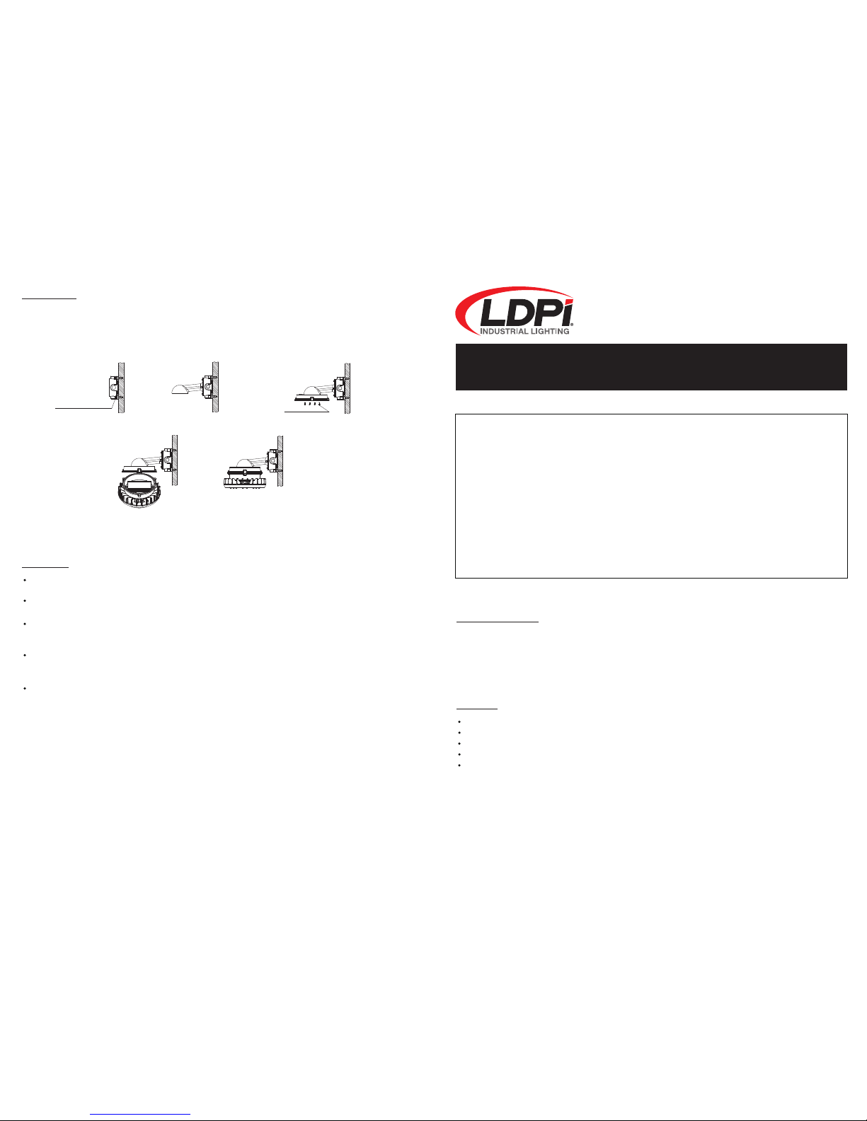
Wall 25°/90°
1. Use the four M8 expansion bolts to attach the bracket to the wall.
2. Use the six M4 hexagon socket screws to attach the driver housing to the bracket.
3. Fixture should be hung on the driver housing; connect the wires.
4. Re-attach the fixture and tighten it with the three M5 socket head cap screws and spring washers.
Servicing
To avoid personal injury, disconnect power to the fixture and allow it to cool down before performing maintenance.
Perform visual, electrical, and mechanical inspections on a regular basis. The environment and frequency of
use should determine this. However, it is recommended that checks should be made at least once a year.
The external glass should be cleaned periodically to ensure continued performance. Clean the glass with a
clean, damp, non-abrasive, lint-free cloth. If this is not sufficient, use a mild soap or a liquid cleaner. Do not
use an abrasive, strong alkaline, or acid cleaner as damage may occur.
Inspect the cooling fins on the fixture to ensure that they are free of any contamination (i.e. excessive dust
build-up). Clean with a non-abrasive cloth if needed. Mechanically check to make sure all parts are properly
assembled.
Electrically check to make sure that all connections are clean and tight.
step1 step2
step3
step5step4
M4
Socket head cap screws
(Gasket+Washers induded) M8
Expansion bolts
D-1319 REV: 25DEC17
Page: 4
Page: 1
LDPI, Inc. 1-800-854-0021 Web: www.ldpi-inc.com E-mail: [email protected] LDPI, Inc. 1-800-854-0021 Web: www.ldpi-inc.com E-mail: [email protected]
Page 2
Terminal
Block
LED Driver
(-)
(+)
(LEAD WIRES
TO LED LOAD)
WHITE (NEUTRAL)
GREEN (GROUND)
BLACK (LINE)
AC INPUT
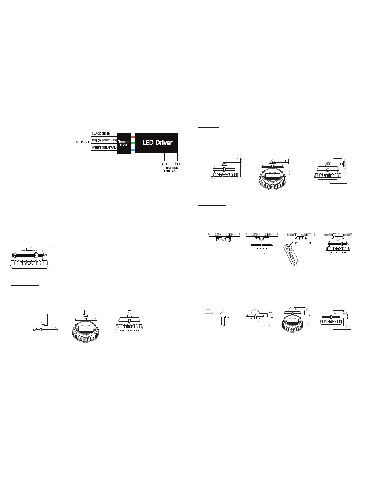
General Wiring Diagram
Installation and Operation
Product Size
Pendant Type
CAUTION: Turn off electrical power at
fuse or circuit breaker box before
wiring fixture to the power supply.
Connecting panels to the AC source
supply:
All units must be individually connected to the AC supply.
Black = Line
White = Neutral
Green = Ground
Electrical Connection:
1. Loosen the three M5 socket head cap screws with spring washers on the driver housing Cover.
2. The entry hole of the driver housing is 3/4” NPT. Attach to suitable conduit.
3. Run the wire from outside through the conduit and the entry hole of driver housing, and then connect it to
the Terminal Block.
4. Re-attach the housing cover and tighten it with the three M5 socket head cap screws and spring washers
at torque value 5 N-m.
1. Attach the driver housing to the threaded 3/4" pipe and tighten with M4 fastening screws.
2. Connect the electrical part.
3. Re-attach the fixture to the driver housing and tighten it with the three M5 socket head cap screws and
spring washers.
Φ262mm /10.3in
155mm / 6.1in
step1
step2
step3
Set screw
M4
Socket head cap screws
M5
U-Bracket
1. Use the four M8 expansion bolts to attach the bracket to the wall.
2. Connect electrical part.
3. Re-attach the fixture to the driver housing and tighten it with the three M5 socket head cap screws and
spring washers. Adjust the angle of the fixture with the M4 screws.
Ceiling Mount
Stanchion 25°/90°
1. Use the four M8 expansion bolts to attach the bracket to the ceiling.
2. Use the six M4 hexagon socket screws to attach the driver housing to the bracket.
3. Fixture should be hung on the driver housing; connect the wires.
4. Re-attach the fixture and tighten it with the three M5 socket head cap screws and spring washers.
1. Screw the bracket to the pole then tighten the M5 fastening screws.
2. Use six M4 hexagon socket screws to attach the driver housing to the bracket.
3. Connect the electrical part.
4. Re-attach the fixture to the driver housing and tighten it with the three M5 socket head cap screws and
spring washers.
step1
step2
Socket head cap screws
M5
Screws
M4
(Gasket+Washers induded) M8
Expansion bolts
step3
(Gasket+Washers induded) M8
Expansion bolts
step1
step2
M4 Socket head cap screws
M4
step3
step4
M5
Socket head cap screws
step1
step2
step3
step4
M4
Socket head cap screws
Screws
M5
M5
Socket head cap screws
Page: 2 Page: 3
LDPI, Inc. 1-800-854-0021 Web: www.ldpi-inc.com E-mail: [email protected]
LDPI, Inc. 1-800-854-0021 Web: www.ldpi-inc.com E-mail: [email protected]
 Loading...