

Page 1
CONFIDENTIAL INFORMATION
This document is the exclusive property of LDL Technology.
No content may be transmitted or reproduced in any form without written permission.
Mounting procedure TCU Ref : C3131320010
Version : A1
Diffusion : Internal External
Status : Confidential Limited Extended
Mounting procedure
TCU
Reference : C3131320010 Version A1
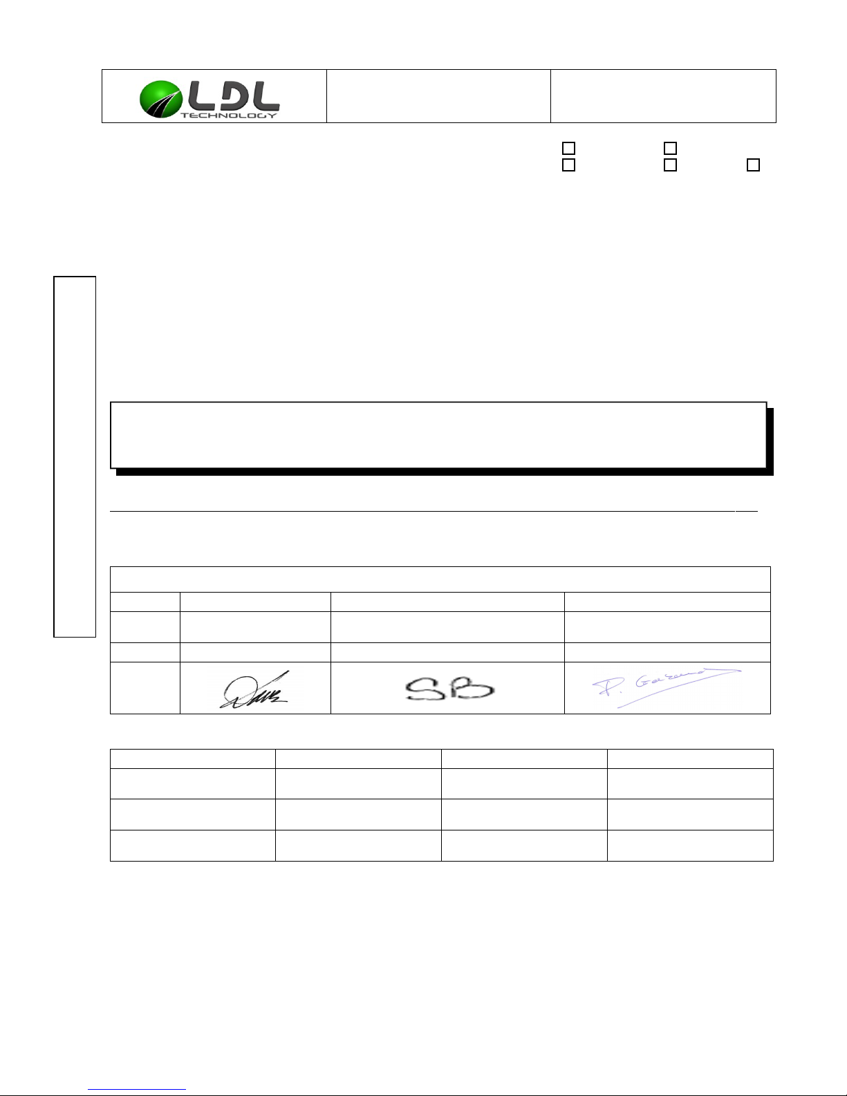
Author Check Approver
Name and
Department
D. LUCE (MD) S.BAIGET (SY) P. GABAUDAN (PM)
Date
13/04/15 15/04/15 15/04/15
Signature
COMPANY NAME DATE SIGNATURE
C3131320010-A1-TCU_Mounting_Specification.odt LDL Technology SAS – Toulouse – France 1/ 16
Copyrights 2015
Page 2
CONFIDENTIAL INFORMATION
This document is the exclusive property of LDL Technology.
No content may be transmitted or reproduced in any form without written permission.
Mounting procedure TCU Ref : C3131320010
Version : A1
MODIFCATION LIST :
Version
Modification date Chapter / pages Comments Author
A0 13/04/2015 All Creation D.LUCE
A1 17/06/2015 §8 Modification of regulatory notices M.GUERIN
C3131320010-A1-TCU_Mounting_Specification.odt LDL Technology SAS – Toulouse – France 2/ 16
Copyrights 2015
Page 3
CONFIDENTIAL INFORMATION
This document is the exclusive property of LDL Technology.
No content may be transmitted or reproduced in any form without written permission.
Mounting procedure TCU Ref : C3131320010
Version : A1
Chapter :
1. PURPOSE .................................................................................................................................. 4
2. TCU PRODUCT DESCRIPTION. ............................................................................................... 4
2.1. Part Numbers ....................................................................................................................... 4
2.2. External Description ............................................................................................................. 4
3. MAIN FEATURES ...................................................................................................................... 6
3.1. Electronic Features .............................................................................................................. 6
3.2. Mechanical Features ........................................................................................................... 6
3.3. Connector Pin Out ............................................................................................................... 6
4. TCU MOUNTING INTERFACE. ................................................................................................. 7
5. TCU MOUNTING RECOMMENDATIONS ................................................................................. 7
6. TCU POWER SUPPLY CONNECTION ..................................................................................... 9
7. TCU LOCATING RECOMMENDATIONS ................................................................................ 11
8. FCC/IC Regulatory notices ....................................................................................................... 13
8.1. Modification statement: ...................................................................................................... 13
8.2. Interference statement: ...................................................................................................... 13
8.3. Radiation Exposure Statement: ......................................................................................... 13
8.4. FCC Class B digital device notice ..................................................................................... 14
9. APPENDIX ................................................................................................................................ 14
C3131320010-A1-TCU_Mounting_Specification.odt LDL Technology SAS – Toulouse – France 3/ 16
Copyrights 2015
Page 4
CONFIDENTIAL INFORMATION
This document is the exclusive property of LDL Technology.
No content may be transmitted or reproduced in any form without written permission.
Mounting procedure TCU Ref : C3131320010
Version : A1
1. PURPOSE
This document is the Mounting procedure of the TCU.
TCU is a part of a Tire Pressure Monitoring System.
The Telematic Control Unit (TCU) collects information on the vehicle and transmits it over the
GSM network to a back-end server. It can capture data from CAN, GPS and TPMS.
2. TCU PRODUCT DESCRIPTION.
2.1. PART NUMBERS
TCU Part Number Region Model
13 132 0000 Europe Middle East Africa (EMEA) 13 123
13 144 0000 Europe Middle East Africa (EMEA) 13 144
14 119 0000 North America (NA) 14 119
15 046 0000 North America (NA) 14 119
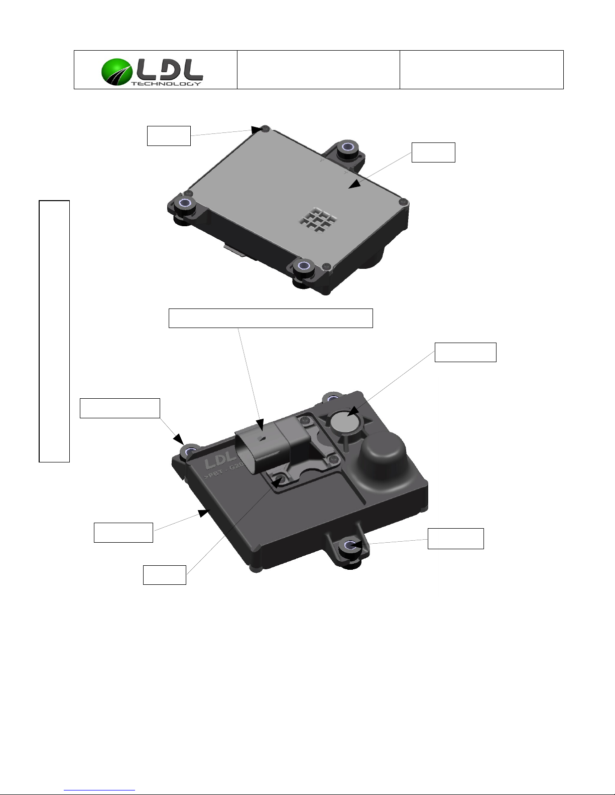
2.2. EXTERNAL DESCRIPTION
Part Material Characteristics
TCU all electronic parts -
1 Housing PBT GF20 - UL94 V0 Black
1 Cover PBT GF20 - UL94 V0 Black
1 10 Ways FCI PBT GF20 - UL94 V0 Black
8 Screws Steel C 1018 -
3 Silent-blocks EPDM Black
3 Spacers Stainless steel A2 -
1 Nitto Vent NA (assembly) Black
C3131320010-A1-TCU_Mounting_Specification.odt LDL Technology SAS – Toulouse – France 4/ 16
Copyrights 2015
Page 5
CONFIDENTIAL INFORMATION
This document is the exclusive property of LDL Technology.
No content may be transmitted or reproduced in any form without written permission.
Mounting procedure TCU Ref : C3131320010
Version : A1
C3131320010-A1-TCU_Mounting_Specification.odt LDL Technology SAS – Toulouse – France 5/ 16
Copyrights 2015
Nitto vent
Spacer
Housing
10 Ways Delphi Connector APEX 150
Silent block
screw
Cover
screw
Page 6
CONFIDENTIAL INFORMATION
This document is the exclusive property of LDL Technology.
No content may be transmitted or reproduced in any form without written permission.
Mounting procedure TCU Ref : C3131320010
Version : A1
3. MAIN FEATURES
3.1. ELECTRONIC FEATURES
Power supply (5A fuse protected) 7 to 32 V
Operating current 1 A
Temperature operating range -40°C to 85°C
Storage temperature range 0 to 30°C
Legal Regulations
R&TTE (99/5/EC)
FCC/IC
PTCRB
E marking
Antennas (GSM, GPS and RF) Internal
3.2. MECHANICAL FEATURES
Total Mass 256 g
Dimensions (L x W x H) 123 x 120 x 50 mm
Connector (10 Ways) FCI - Delphi Connector APEX 150
Tightness IP 68 & IP69K
Mounting LDL Brackets (see §4)
Wiring LDL harnesses (see §6)
3.3. CONNECTOR PIN OUT
Pin number Mnemonic Function
1 CAN HI CAN High
2 - Reserved
3 CAN LO CAN Low
4 BBM+ BBM positive
5 IGN Ignition status (KL15)
6 - Reserved
7 VBAT Vehicle battery positive (KL30)
8 - Reserved
9 GND Vehicle battery negative (KL31)
10 TEMP BBM temperature
C3131320010-A1-TCU_Mounting_Specification.odt LDL Technology SAS – Toulouse – France 6/ 16
Copyrights 2015
Page 7
CONFIDENTIAL INFORMATION
This document is the exclusive property of LDL Technology.
No content may be transmitted or reproduced in any form without written permission.
Mounting procedure TCU Ref : C3131320010
Version : A1
4. TCU MOUNTING INTERFACE.
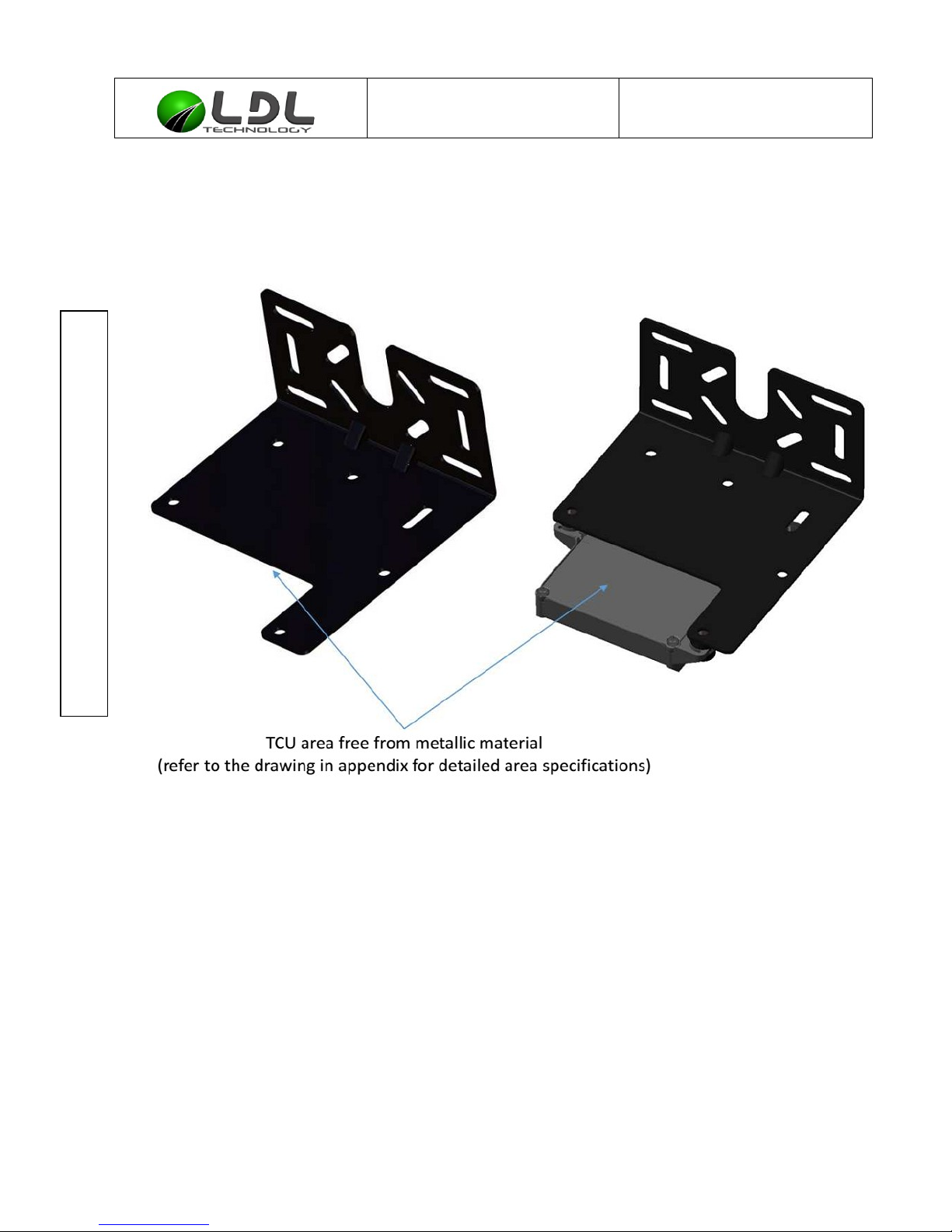
The TCU is mounted on a plane surface fixed on the vehicle frame. The TCU has 3 mounting
points equipped with silent blocks. The TCU must be fixed on a support (available on demand).
This support (TCU interface) is defined in the appendix.
5. TCU MOUNTING RECOMMENDATIONS
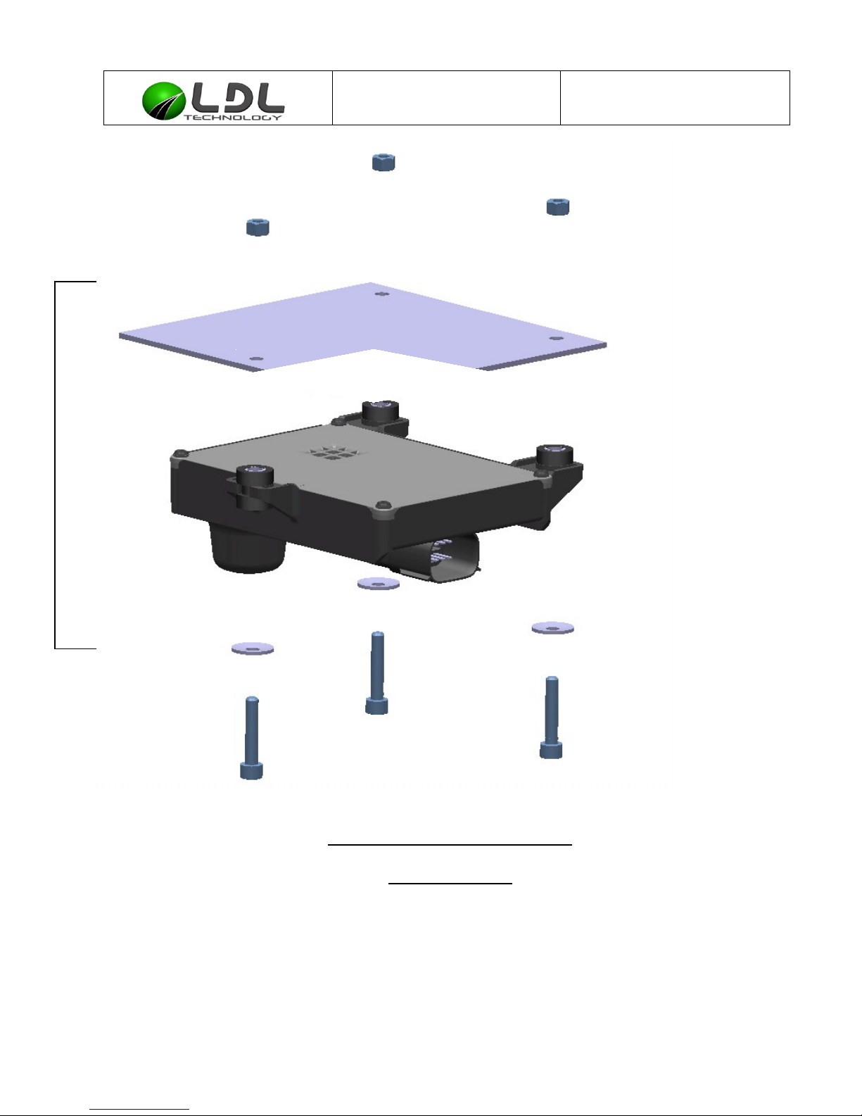
Screws (not provided by LDL) must be tightened @ 4,5 Nm +/-0,5 Nm. It's recommended to use
an elastic washer (Belleville type) between screw head and silent block with spacer. Stainless
steel is recommended.
M6 bolts are recommended, the screw for a fixation on a base plate fixation in thickness 2mm
must have a length equal or higher than 20mm.
C3131320010-A1-TCU_Mounting_Specification.odt LDL Technology SAS – Toulouse – France 7/ 16
Copyrights 2015
Page 8
CONFIDENTIAL INFORMATION
This document is the exclusive property of LDL Technology.
No content may be transmitted or reproduced in any form without written permission.
Mounting procedure TCU Ref : C3131320010
Version : A1
Nut
M6
Interface
TCU
Washer
Screw
M6
TCU Assembled onto support
TCU Assembly
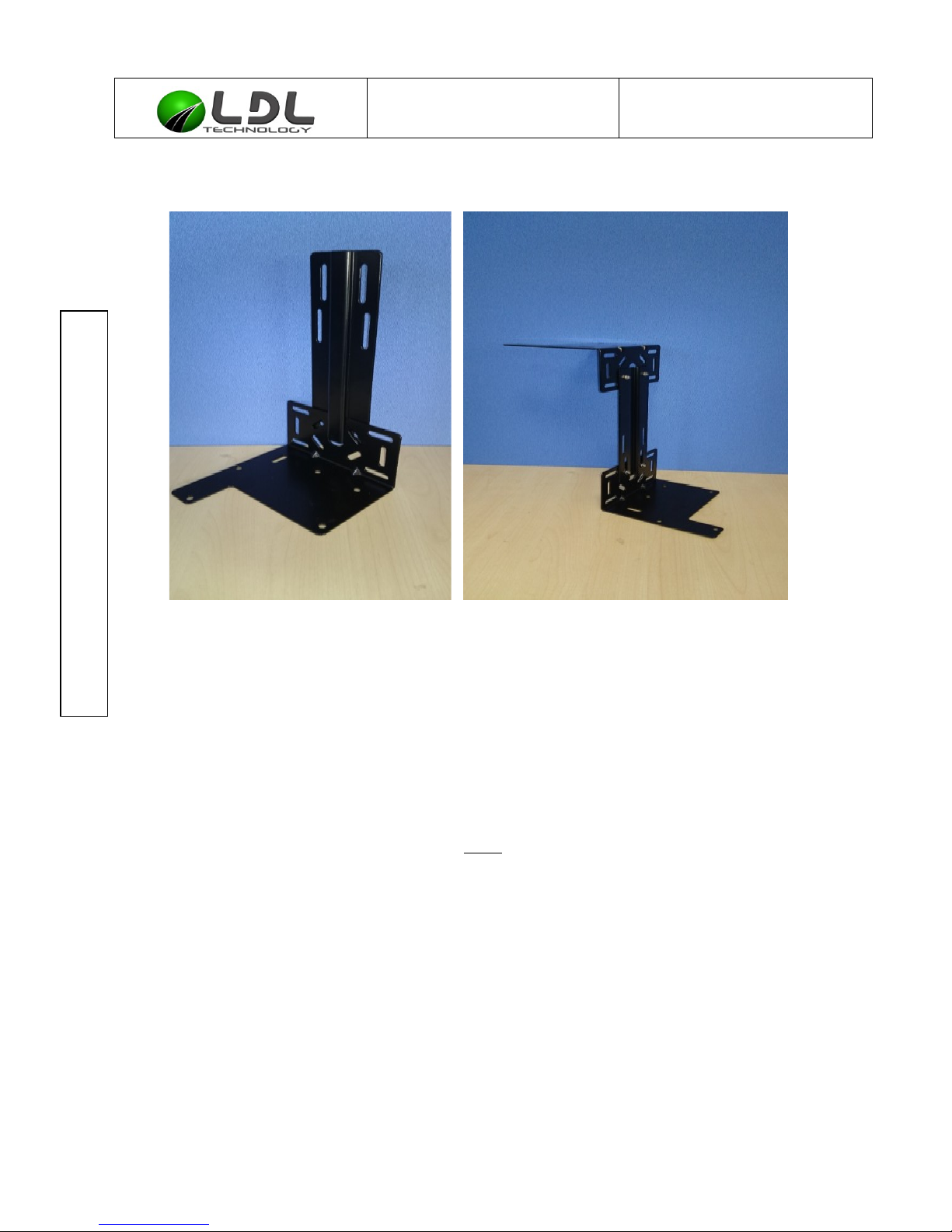
Universal fixation kit can be provided by LDL. It consists of a base plate and an extension plate.
A combination of these parts is able to fit all vehicle types.
C3131320010-A1-TCU_Mounting_Specification.odt LDL Technology SAS – Toulouse – France 8/ 16
Copyrights 2015
Page 9
CONFIDENTIAL INFORMATION
This document is the exclusive property of LDL Technology.
No content may be transmitted or reproduced in any form without written permission.
Mounting procedure TCU Ref : C3131320010
Version : A1
LDL TCU bracket combinations
To link a base support to an extension support , 2 bolts are needed, type M6, length 16mm,
with 2 M6 washers (1 standard type and 1 Belleville type).
6. TCU POWER SUPPLY CONNECTION
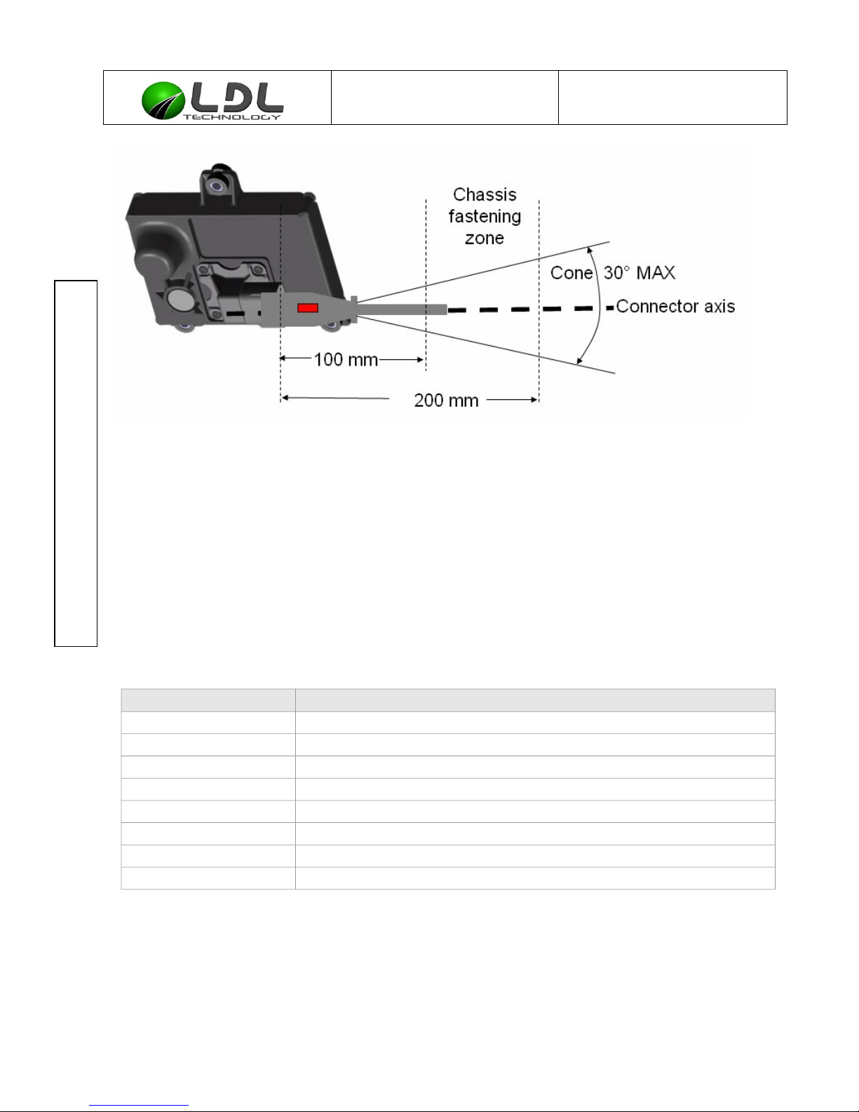
Cable must be fastened between 100mm and 200 mm away from its TCU starting point.
Verify that no tension stress is applied onto the harness between TCU connector and the
fixation point onto the vehicle chassis AND after connection of the harness connector onto the
TCU connector.
From the TCU connector base to the fixation point away TCU (100 to 200 mm), the harness
cable must be in line as much as possible with the TCU connector terminal axis and not curved
over 30° see picture on next page below.
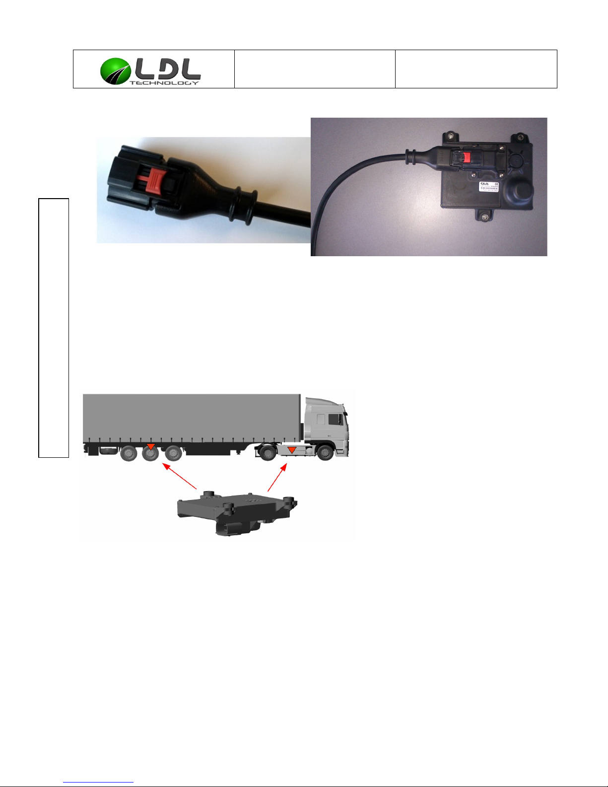
The connector must be secured after clipping (move the red CPA (Connector Position
Assurance) onto the harness connector toward the TCU connector)
C3131320010-A1-TCU_Mounting_Specification.odt LDL Technology SAS – Toulouse – France 9/ 16
Copyrights 2015
Page 10
CONFIDENTIAL INFORMATION
This document is the exclusive property of LDL Technology.
No content may be transmitted or reproduced in any form without written permission.
Mounting procedure TCU Ref : C3131320010
Version : A1
Cable management in the TCU neighborhood.
Incorrect wiring will prevent the system from operating properly.
TCU has to be connected to +12V or +24V through 5A fuse protection.
TCU must be connected on Ignition (IGN).
When TCU and ECU or EBS are connected to a same CAN network, they must share the
same ground.
LDL Technology can provide the wiring harness (see table below) :
Nota : This cable has a minimum curvature radius about 80mm.
Reference Description
11 231 0000 Harness CAN (#1-Can)
11 232 0000 Harness (#1)
15 018 0000 Cable TCU CAN 1,2m - Wabco
15 017 0000 Cable TCU CAN 1,2m - EB+ gen3 - Haldex
15 016 0000 Cable TCU CAN Y 1,2m - EB+ gen2 - Haldex
15 015 0000 Cable TCU CAN 1,2m - EB+ gen2 - Haldex
15 014 0000 Cable TCU CAN 1,2m Deutsh 4 contacts 0462-201-16141 - Knorr
15 024 0000 Cable TCU CAN 1,2m – WABCO GIO5
C3131320010-A1-TCU_Mounting_Specification.odt LDL Technology SAS – Toulouse – France 10/ 16
Copyrights 2015
Page 11
CONFIDENTIAL INFORMATION
This document is the exclusive property of LDL Technology.
No content may be transmitted or reproduced in any form without written permission.
Mounting procedure TCU Ref : C3131320010
Version : A1
LOCKED POSITION OF THE CPA
UNLOCKED POSITION OF THE CPA
TCU harness Delphi APEX 150 Clip holder, IP69K
7. TCU LOCATING RECOMMENDATIONS
The TCU must be fixed horizontally and upside down (connector side facing the ground):
The TCU must be free from any metallic shield in the direction of the connector side.
The antenna should be cleared as possible to optimize RF communication and reduce areas of
non-receipt.
There must be a free area of minimum 5cm wide around the TCU in all directions.
TCU must not be exposed to gritting.
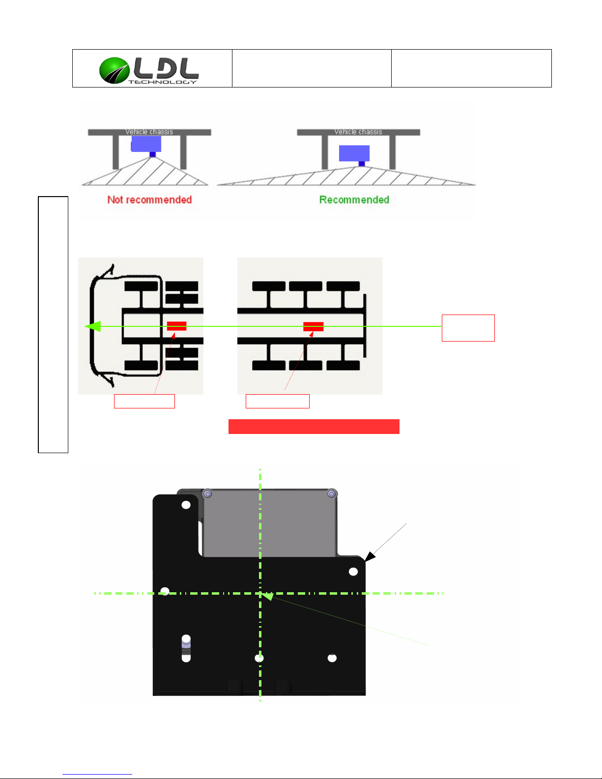
Each TCU must be at a central point between the wheels that it has to receive, and aligned on
the vehicle axis. Distance between TCU and WUS must not exceed 3 meters.
When trailer is equipped with an EBS, TCU bracket should be fixed to EBS bracket.
C3131320010-A1-TCU_Mounting_Specification.odt LDL Technology SAS – Toulouse – France 11/ 16
Copyrights 2015
Page 12
CONFIDENTIAL INFORMATION
This document is the exclusive property of LDL Technology.
No content may be transmitted or reproduced in any form without written permission.
Mounting procedure TCU Ref : C3131320010
Version : A1
MANDATORY TCU location:
C3131320010-A1-TCU_Mounting_Specification.odt LDL Technology SAS – Toulouse – France 12/ 16
Copyrights 2015
Truck TCU Trailer TCU
Vehicle
axis
TCU
TCU
TCU-one point
fixation side
In green
Vehicle axis
Page 13
CONFIDENTIAL INFORMATION
This document is the exclusive property of LDL Technology.
No content may be transmitted or reproduced in any form without written permission.
Mounting procedure TCU Ref : C3131320010
Version : A1
8. FCC/IC REGULATORY NOTICES
8.1. MODIFICATION STATEMENT:
LDL Technology has not approved any changes or modifications to this device by the user. Any
changes or modifications could void the user’s authority to operate the equipment.
LDL Technology n’approuve aucune modification apportée à l’appareil par l’utilisateur, quelle
qu’en soit la nature. Tout changement ou modification peuvent annuler le droit d’utilisation de
l’appareil par l’utilisateur.
8.2. INTERFERENCE STATEMENT:
This device complies with Part 15 of the FCC Rules and Industry Canada licence-exempt RSS
standard(s). Operation is subject to the following two conditions: (1) this device may not cause
interference, and (2) this device must accept any interference, including interference that may
cause undesired operation of the device.
Le présent appareil est conforme aux CNR d'Industrie Canada applicables aux appareils radio
exempts de licence. L'exploitation est autorisée aux deux conditions suivantes : (1) l'appareil ne
doit pas produire de brouillage, et (2) l'utilisateur de l'appareil doit accepter tout brouillage
radioélectrique subi, même si le brouillage est susceptible d'en compromettre le
fonctionnement.
8.3. RADIATION EXPOSURE STATEMENT:
This device complies with FCC/IC radiation exposure limits set forth for an uncontrolled
environment and meets the FCC radio frequency (RF) Exposure Guidelines and RSS 102 of ‐
the IC radio frequency (RF) Exposure rules. The antenna should be installed and operated with
minimum distance of 20 cm between the radiator and your body. This transmitter must not be
co-located or operating in conjunction with any other antenna or transmitter.
Le présent appareil est conforme à l'exposition aux radiations FCC / IC définies pour un
environnement non contrôlé et répond aux directives d'exposition de la fréquence de la FCC
radiofréquence (RF) et RSS 102 de la fréquence radio (RF) IC règles d'exposition. L'antenne ‐
doit être installée de façon à garder une distance minimale de 20 centimètres entre la source
de rayonnements et votre corps. L'émetteur ne doit pas être colocalisé ni fonctionner
conjointement avec une autre antenne ou un autre émetteur.
C3131320010-A1-TCU_Mounting_Specification.odt LDL Technology SAS – Toulouse – France 13/ 16
Copyrights 2015
Page 14
CONFIDENTIAL INFORMATION
This document is the exclusive property of LDL Technology.
No content may be transmitted or reproduced in any form without written permission.
Mounting procedure TCU Ref : C3131320010
Version : A1
8.4. FCC CLASS B DIGITAL DEVICE NOTICE
This equipment has been tested and found to comply with the limits for a Class B digital device,
pursuant to part 15 of the FCC Rules. These limits are designed to provide reasonable
protection against harmful interference in a residential installation. This equipment generates,
uses and can radiate radio frequency energy and, if not installed and used in accordance with
the instructions, may cause harmful interference to radio communications. However, there is no
guarantee that interference will not occur in a particular installation. If this equipment does
cause harmful interference to radio or television reception, which can be determined by turning
the equipment off and on, the user is encouraged to try to correct the interference by one or
more of the following measures:
- Reorient or relocate the receiving antenna.
- Increase the separation between the equipment and receiver.
- Connect the equipment into an outlet on a circuit different from that to which the receiver
is connected.
- Consult the dealer or an experienced radio/TV technician for help.
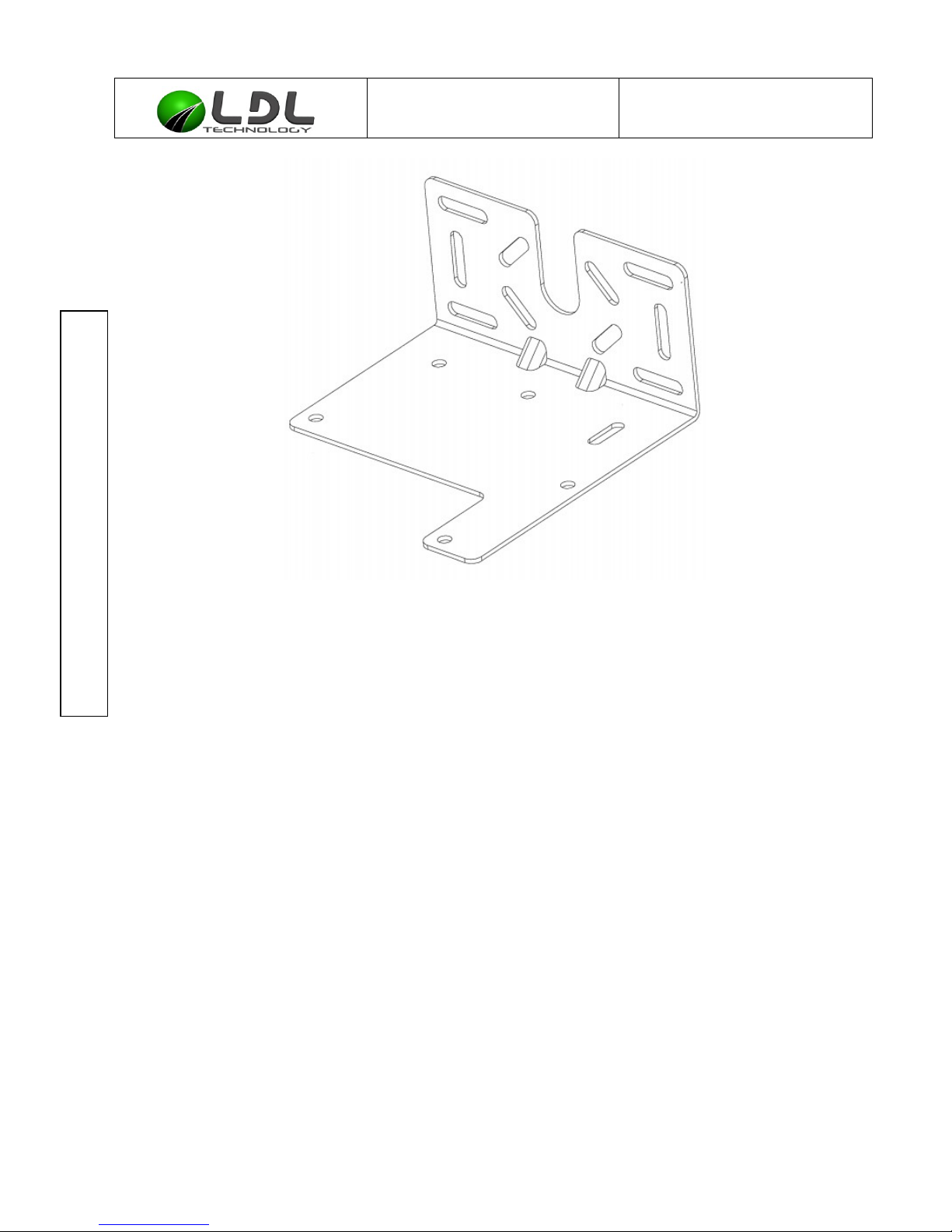
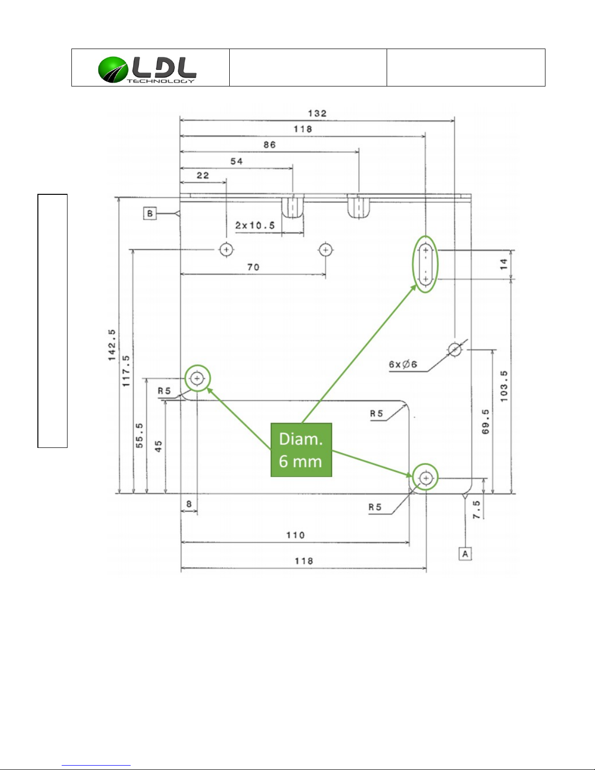
9. APPENDIX
TCU interface dimension, see drawing below
C3131320010-A1-TCU_Mounting_Specification.odt LDL Technology SAS – Toulouse – France 14/ 16
Copyrights 2015
Page 15
CONFIDENTIAL INFORMATION
This document is the exclusive property of LDL Technology.
No content may be transmitted or reproduced in any form without written permission.
Mounting procedure TCU Ref : C3131320010
Version : A1
Bracket in steel, thickness 2mm, with surface treatment to withstand at least 1500hr NSS
C3131320010-A1-TCU_Mounting_Specification.odt LDL Technology SAS – Toulouse – France 15/ 16
Copyrights 2015
Page 16
CONFIDENTIAL INFORMATION
This document is the exclusive property of LDL Technology.
No content may be transmitted or reproduced in any form without written permission.
Mounting procedure TCU Ref : C3131320010
Version : A1
Interface Drawing
C3131320010-A1-TCU_Mounting_Specification.odt LDL Technology SAS – Toulouse – France 16/ 16
Copyrights 2015
 Loading...