

USER’S GUIDE
LDLC US GOLD
POWER SUPPLY MODULAR UNIT ATX12V FORMAT
LDLC US-550G / LDLC US-650G / LDLC US-750G /
LDLC US-850G / LDLC US-1000G
USER’S GUIDE
LDLC US GOLD
EN
Preface
Every effort has been made to ensure that the information in this document
is accurate. However, the manufacturer and the distributor of this product
assume no responsibility for any error, omission in this document, or use of
the information contain herein.
Please preserve this manual for the life of the equipment.
Congratulations on your purchase!
INFORMATION ABOUT RECYCLING
This product bears the selective sorting symbol for waste electrical and electronic equipment
(WEEE).
This means that this product must be handled pursuant to European Directive 2002/96/EC in
order to be recycled or dismantled to minimize its impact on the environment.
For further information, please contact your local or regional authorities.
Electronic products not included in the selective sorting process are potentially dangerous for
the environment and human health due to the presence of hazardous substances.
USER’S GUIDE
LDLC US GOLD
EN
Carton contents
• LDLC US GOLD series Power Supply Unit
• Modular cable pack
• User Guide
• AC power cord
• PSU bag
Technical features
• A high performance for energy savings. 80 PLUS Gold Certication: High energetic
efficiency. The 80 PLUS Certication guarantees greater than 87%, 90% and 87%
efficiency at 20%, 50% and 100% operating loads, respectively.
• Japanese capacitors of 105°C nominal provides a quality reliability/performances.
• A single +12V monorail for a better current distribution.
• Active PCF. A correction of the active power factor >0.90 at full load that provides
a clean and reliable current.
• An advanced cable set covering all kind of PC.
• A DC fan of 120mm provides an excellent air ow with a very low noise level. 12V
DC, 66.5CFM/min, <34.5 dB(A), This fan is only for power supply internal cooling
purpose, not for system cooling.
• Hybrid mode:
◦ The Normal Fan Control setting (button pushed) enables the fan to rotate
continuously in Silent Mode and Cooling Mode, depending on the system load.
◦ The Hybrid Silent Fan Control setting (button not pushed) enables the power
supply to run in Fanless Mode up to 20 % (± 5 %) of the maximum rated
load at 25 degrees. When the load further increases, the fan control will keep
regulating perfect cooling through the Silent Mode or Cooling Modes.
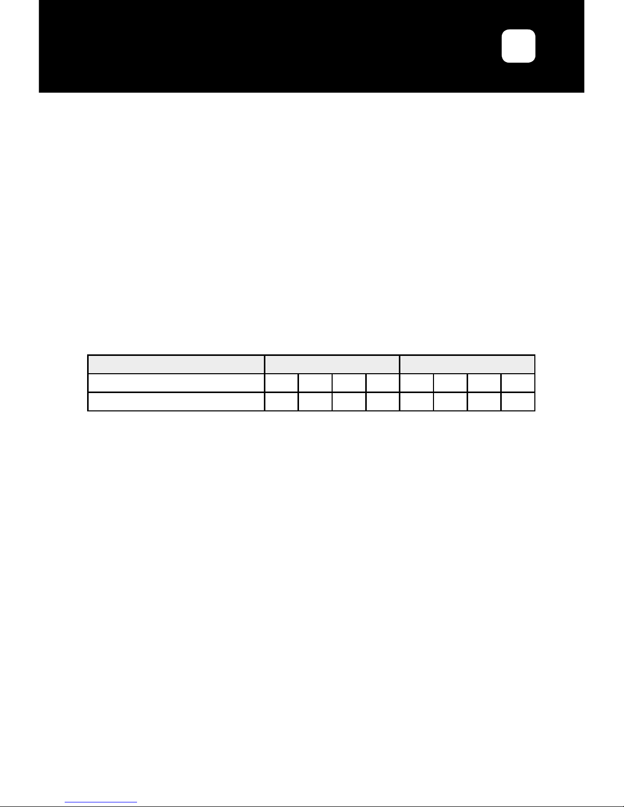
80 PLUS Test Type
115V internal non-redundant 230V internal redundant
Power Supply use rate 10% 20% 50% 100% 10% 20% 50% 100%
80 PLUS GOLD - 87% 90% 87% - 87% 90% 87%

USER’S GUIDE
LDLC US GOLD
EN
• Ample +12V Output: Enhanced +12V current output capability increases utilisation
possibilities by ensuring that there is adequate power to support all the powerhungry system components.
• Ultra-Ventilation [Honeycomb Structure]: Honeycomb-shaped ventilation holes
optimize airow for improved cooling and reduced noise.
• Fully Modular Cabling: Easy to install and maintain and provides maximum
exibility.
• System protection: OPP (overload protection), OVP (power surge protection), SCP
(short circuits protection), OCP (over current protection) OTP (over temperature
protection).
• MTBF (medium time between failures) > 100,000 hours at 25°C, excluding DC fan
• Dimension (WxLxH): 140 x 150 x 86mm +/-1mm
Model
LDLC US-550G LDLC US-650G
AC input
Voltage input 100-240 VAC 100-240 VAC
Intensity input 8-4 A 9-4.5 A
Frequency 50-60 Hz 50-60 Hz
Voltage output
Max. Intensity Max. Power Max. Intensity Max. Power
+3.3 V 20 A
100 W
20 A
100 W
+5 V 20 A 20 A
+12 V 45 A 540 W 54 A 648 W
-12 V 0.3 A 3.6 W 0.3 A 3.6 W
+5 VSB 3 A 15 W 3 A 15 W
Total Power 550 W 650 W

USER’S GUIDE
LDLC US GOLD
EN
Introduction to the power connectors
Model
Connector of the
principal power
supply (20+4 pins)
ATX 12V
(4+4 pins)
PCI-E (6+2
pins)
SATA (5 pins)
Device + FDD (4
pins)
LDLC US-550G
1 1 2 6 1 x (3 HDD + FDD)
610 mm 650 mm 675 + 75 mm
1 x (450 + 120 mm), 1x (450
+ 120 + 120 + 120 mm)
450 + 120 + 120 + 101 mm
LDLC US-650G
1 1 4 8 1 x (3 HDD + FDD)
610 mm 650 mm 2 x (675 + 75 mm)
2 x (450 + 120 + 120 +
120 mm)
450 + 120 + 120 + 101 mm
LDLC US-750G
1 2 4 8 1 x (3 HDD + FDD)
610 mm 2 x 650 mm 2 x (675 + 75 mm)
2 x (450 + 120 + 120 +
120 mm)
450 + 120 + 120 + 101 mm
LDLC US-850G
1 2 6 10 1 x (2 HDD, 3 HDD + FDD)
610 mm 2 x 650 mm 3 x (675 + 75 mm)
1 x (450 + 120 mm),
2 x (450 + 120 + 120 + 120 mm)
1 x (350 + 120 mm),
1 x (450 + 120 + 120 + 101 mm)
LDLC US-1000G
1 2 6 10 1 x (2 HDD, 3 HDD + FDD)
610 mm 2 x 650 mm 3 x (675 + 75 mm)
1 x (450 + 120 mm),
2 x (450 + 120 + 120 + 120 mm)
1 x (350 + 120 mm),
1 x (450 + 120 + 120 + 101 mm)
LDLC US-750G LDLC US-850G LDLC US-1000G
AC input
Voltage input 100-240 VAC 100-240 VAC 100-240 VAC
Intensity input 10-5 A 12-6 A 13-6.5 A
Frequency 50-60 Hz 50-60 Hz 50-60 Hz
Voltage output
Max.
Intensity
Max.
Power
Max.
Intensity
Max.
Power
Max.
Intensity
Max.
Power
+3.3 V 20 A
100 W
20 A
100 W
25 A
125 W
+5 V 20 A 20 A 25 A
+12 V 62 A 744 W 70 A 840 W 83 A 996 W
-12 V 0.3 A 3.6 W 0.3 A 3.6 W 0.3 A 3.6 W
+5 VSB 3 A 15 W 3 A 15 W 3 A 15 W
Total Power 750 W 850 W 1000 W

USER’S GUIDE
LDLC US GOLD
EN
1. Installation
Before installation, please read the entire manual.
Step A : Construction of a whole new system
(If you replace your current power supply unit, please go to step B).
1. Please make sure that the LDLC PSU is not connected to a power cord.
2. Follow the directions in your case manual and install the LDLC power supply
using the supplied screws. Do not over tighten the screws.
3. Connect the power connectors to your motherboard and peripheral devices. DO
NOT force the connector into place; the connectors are keyed so they can only t
one way. Make sure that all cables and wires are properly connected.
• Connect the main power supply connector to your motherboard 24/20 pins.
• Connect the 4/8 pins + 12V power supply connector to the motherboard
according to your needs.
• Connect the 4 pins peripheral power supply connector to the devices.
• SATA connectors are intended to ATA series interface devices.
• Connect the oppy drive power adapter to the oppy drives according to your
needs.
• Connect the PCI-E +12V power connectors to the PCI-E graphic card(s).
Please check your graphic card manual for further details if needed.
4. Close your computer case, connect the power plug to the power supply unit, then
set the power supply unit « I/O » switch on position « I ».
Step B : Current power supply unit replacement
1. Disconnect your PC power cord from all AC sources. Make certain that the
system is turned OFF. If applicable, set the power supply unit’s AC power switch
to “O” (OFF) position.
2. Open the PC case and, if applicable, refer to your PC manufacturer’s User
Manual.
3. Carefully disconnect all the power supply unit’s DC wire harness connectors from
the mainboard and all peripheral connectors.
4. Unscrew the mounting screws securing the power supply unit to the back panel
of the PC case.
5. Carefully remove the power supply unit from the PC system.
6. Now refer to step A.

USER’S GUIDE
LDLC US GOLD
EN
Congratulations! You just nished the installation of your LDLC supply power unit
and your system is now ready!
2. Warnings
• There are high and harmful voltage inside the supply power unit. DO NOT open
the power supply unit case cover. Warranty is declared void just as you remove the
cover. The supply power unit cover must not be covered under any circumstance.
• Please keep the supply power unit away from moisture and operate it in an
advised environment. (Functioning temperature: 0 to 50°C, or 0 to 40°C for the
LDLC US-1000G model; relative humidity: up to 85%)
• Do not insert any object that may obstruct or restrict airow neither inside nor in
front of the ventilation area of the power supply unit.
• USE ONLY the LDLC modular cables provided with the power supply unit.
• The power supply unit if for integration into a computer system and not intended
for external our outdoor usage.
3. Auto-repair
If the supply power unit do not function properly, please check the following elements
before asking any return for repair:
1. Is the electric plug properly connected inside the electric socket and inside the
supply power unit AC entry?
2. Ensure that the « I/O » switch on the supply power unit is on the « I » position.
3. Check that all power supply pins are properly connected on all devices.
4. Please switch off and on several times the power supply unit using the « I/O »
switch with at least 5 seconds lasting off times before resetting the power supply
unit.

USER’S GUIDE
LDLC US GOLD
EN
Warranty Terms
1. Groupe LDLC Contractual Warranty terms
The Groupe LDLC warranty terms certies that this device has no default neither in
parts nor in mounting, and Groupe LDLC offers a 5-year warranty on the power supply
parts delivered with the case starting from the purchasing date. Carefully keep your
receipt. This product is designed for computer use only. Using this product for any other
use will void the warranty. If you are not used to install computing materials, ask for
a professional assistance. The warranty is free for the device regarding normal use
damages. Warranty will be void if it is proved that the device was damaged by abuse,
modication, negligence, non-proper voltage power supply, air/water pollution accidents
and natural disasters.
2. Transfer of ownership and warranties
If the equipment is passed on to another user, this warranty may be transferred.
However, the new user will benet from this warranty only for the remainder of
the original warranty period, under the condition to possess the Original proof of
purchase of the power supply unit.
For more detailed information, please read our “General Terms and Conditions of
Sale” available on our website: http://www.ldlc.com.
3. To contact us
You will nd any related information on our websites: http://www.ldlc.com or on
http://www.ldlc-pro.com.
As an individual, please contact our Technical support:
• By e-mail, via our page: http://www.ldlc.com/faq/
• By phone:
From France: 04 27 46 6000*
From abroad: + 33 4 27 46 6000*
*Call rate: any surcharge, the call rate is the one applied by your operator.
As a professional, please contact our Technical support:
• By e-mail, via our CONTACT page: http://www.ldlc-pro.com/content/2757.html
• By phone (Unique number):
From France: 04 27 46 6005*
From abroad +33 4 27 46 6005*
*Call rate: any surcharge, the call rate is the one applied by your operator.
 Loading...