

Page 1
RVS-8 Eight Channel
Repeater Voting System
Manual Version 1.0
LDG Electronics
1445 Parran Road, PO Box 48
St. Leonard MD 20685-2903 USA
Phone: 410-586-2177
Fax: 410-586-8475
ldg@ldgelectronics.com
www.ldgelectronics.com
Copyright © LDG Electronics 2006. All rights reserved.
Page 2

RVS-8 Eight Channel
Repeater Voting System
Introduction 3
Specifications 3
Overview 4
Installation 6
Setup 7
Operation 9
Application Notes 11
Care and Maintenance 13
Technical Support 14
Warranty and Service 14
Firmware Upgrades 14
Feedback 14
2
Page 3

Introduction
y
y
f
Congratulations on selecting the RVS-8 voter. This system allows you to add up to eight satellite
receivers to your repeater system. It selects the one with the best signal-to-noise ratio and
channels the audio and Carrier Operated Relay (COR) output to your repeater input. A wide
variety of options is available via the front-panel controls and display. You can even "cascade"
up to eight of these units for a system of 64 satellite receivers.
LDG pioneered the automatic, wide-range switched-L tuner in 1995. From its laboratories near
the nation’s capitol, LDG continues to define the state of the art in this field with innovative
automatic tuners and related products for every amateur need.
Specifications
• 8 Channels (expandable)
• True Signal-to-Noise Voting
• Microprocessor Controlled
• Software Upgradable
• Menu Driven, 10 Menus
• Programmable COR and Disable Inputs
• Programmable Hysterisis
• Digital S/N Meter
• Frequency response 30 to 20,000 Hz
• Crosstalk > 60db
• Distortion < 1 db
• Power requirement: 12 Volts DC @ 500 ma
• Board Size: 6 x 9 inches
• Rack Size: 1 Rack unit, 7 inch depth
• Enclosure size: 19 x 7.0 x 1.25 (measured in inches)
Never install antennas or transmission lines over or near
power lines. You can be seriousl
of the antenna, support or transmission line touches a power
line. Alwa
the nearest power line should be at least twice the length o
the longest antenna, transmission line or support dimension.
IMPORTANT SAFETY WARNING
injured or killed if any part
s follow this antenna safety rule: the distance to
3
Page 4
Overview
Your RVS-8 repeater system is a quality, precision instrument that will give you many years of
service; take a few minutes to get to know it.
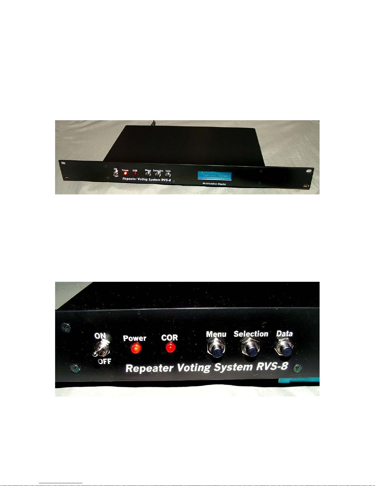
Your RVS-8 is designed to be mounted in a standard 19" rack. The front panel is integrated with
the rack mount. Your RVS-8 comes fully assembled, tested and aligned, and is ready to install
and use.
Front panel controls include:
• Power On/Off
• Power indicator LED
• COR operation LED
• Menu button
• Parameter selection button
• Data input button
4
Page 5
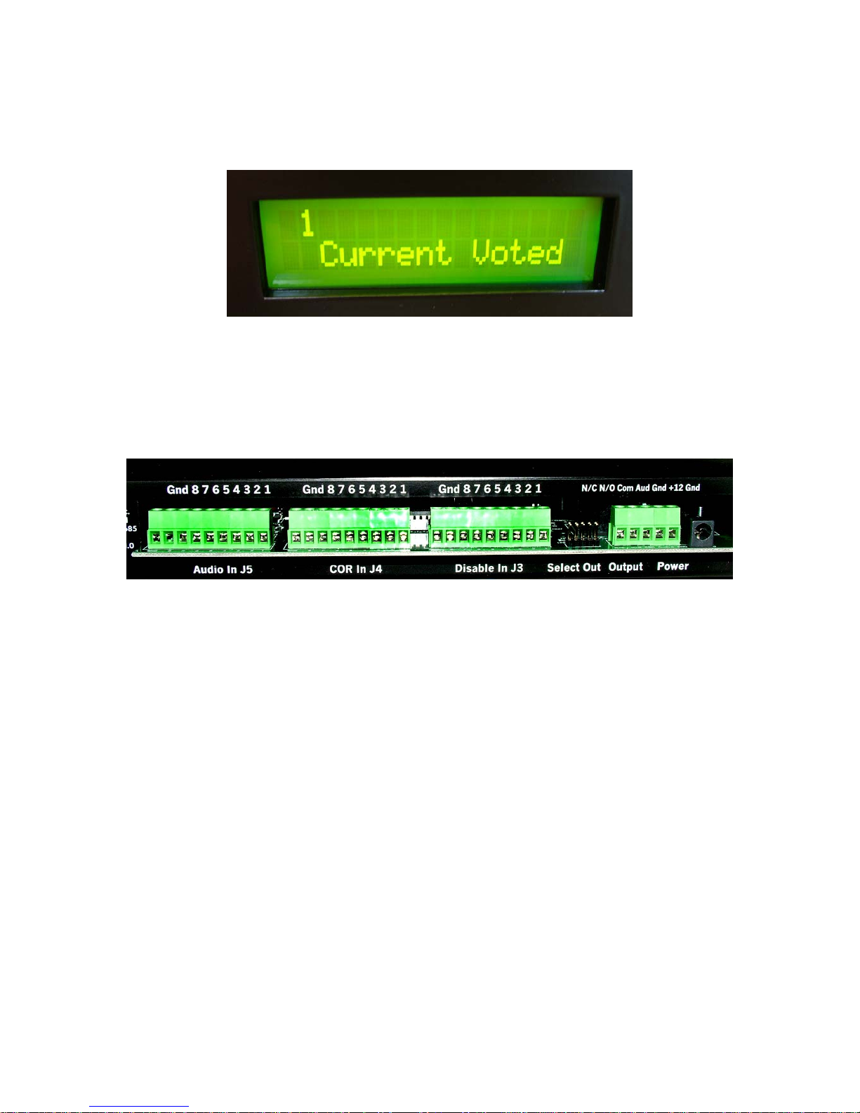
The LDC display shows current system status information, and menu options when selected.
On the rear panel are connections for audio and COR inputs from up to eight receivers, COR
switching output, voted audio output, and DC power input. Other useful outputs are also
provided; see Installation.
5
Page 6
Installation
Your RVS-8 is intended for indoor use only; it is not water resistant. If you install it in a remote
location, you must insure that it is protected from moisture and temperature extremes.
1. Connect the audio output from each of your receivers to the screw connections on the header
labeled "Audio In J5". Each audio input is relative to the ground connection on that header.
2. Connect the corresponding COR output from each receiver to the respective screw
connections on the header labeled "COR In J4". Be sure to correctly match the COR inputs to
the audio inputs on J5; that is, COR 1 matches audio 1, etc.
3. If you wish, you can remotely disable receivers via the inputs on the header labeled "Disable
In J3". To remotely disable a receiver, set the corresponding contact on J3 to either a high or
low voltage state, depending on how you set up that channel in the menu; see Setup. You can
disable as many receivers in this manner as you wish.
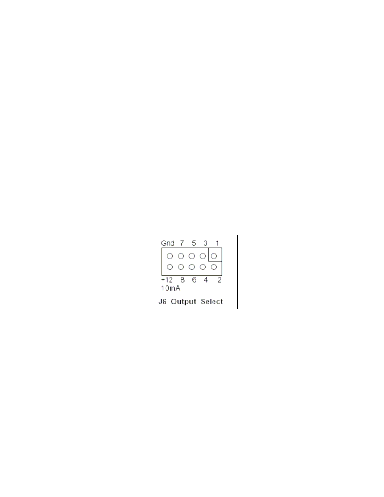
4. The header labeled "Select Out" provides an output indicating which of the eight receivers is
voted. One of the eight pins on this header will be at +12vdc indicating the voted receiver.
The other pins will be at zero volts. +12vdc at 10ma is also provided on this header. All
voltages are relative to the ground connection on this header. You might use this output to
drive an array of LEDs so you could see which receiver is voted from a distance. Use of these
outputs is optional; you may simply leave them disconnected if you wish.
5. The main voter outputs are on the header labeled "Output". Audio output and its dedicated
ground are the rightmost two connectors on this header. COR output is the leftmost three,
providing normally closed, normally open and common connections. The COR outputs are
"dry" contact closures; no voltages are output on these connectors.
6. DC power input is via the coaxial connector labeled "Power". Connect this to a source of 12
volts DC capable of providing at least 500 ma, using the provided 2.5 by 5.5 mm coaxial
plug. Best practice is a regulated DC power supply connected to the AC line through a highquality surge protector.
6
Page 7

Setup
Setup your RVS-8 via the front panel buttons and LDC display. Setup data is stored in nonvolatile EEPROM, and remains intact when power is removed.
Hysteresis
The hysteresis level is the amount of signal-to-noise ratio improvement needed over the currently
voted site for a new site to be voted. Press the Menu button until the present hysteresis value is
displayed. Press the Data button to select the desired value. Available values are 0 - 8. You
should adjust this to a higher value if you experience excessive switching between receivers. A
higher value requires more improvement in the signal-to-noise ratio for switching to occur. The
normal value should be 3 or 4.
Disabled Channels
Press the Menu button until the presently disabled channels are displayed. To disable or enable a
channel, press the Selection button to scroll across to the desired channel. Press the Data button
to toggle between enabled and disabled. The channel is disabled when the channel number
appears in the Disabled Channels display.
This display also reflects channels disabled via hardware connected to J3. Channels disabled in
software via this menu cannot be enabled via hardware, and vice versa.
Be sure not to disable all channels. This would effectively turn off the repeater as no inputs would
be passed through.
7
Page 8

Disable Active State
You can choose whether a receiver is disabled by means of a high or low voltage state input to J3.
This selection can be made for each channel; that is, you can set each channel to either high or
low separately. Press the Menu button until the "Dis Active State" menu is displayed. Press the
Selection button until the desired channel is displayed, then press the Data button to select high
(HI) or low (LO).
Active HI means your controller or other external device must produce a positive-going voltage
(6.5 to 20 volts) when the channel is to be disabled, and a low-going voltage (0.0 to 4.5 volts)
when the channel is to be enabled. Active LO means that your controller or other external device
must provide a low-going voltage (0.0 to 4.5 volts) when the channel is to be disabled, and a high
going voltage (6.5 to 20 volts) when the channel is to be enabled.
COR Active State
You can choose whether a high or low voltage state indicates an active COR input on J4. This
selection can be made for each channel; that is, you can set each to channel to either high or low
separately. Press the Menu button until the "COR Active State" menu is displayed. Press the
Selection button until the desired channel is displayed, then press the Data button to select high
(HI) or low (LO).
Active HI means that your receiver COR must produce a positive-going voltage (6.5 to 20 volts)
when the squelch is open (receiving a signal) and a low-going voltage (0.0 to 4.5 volts) when the
squelch is closed (no signal). Active LO means that your receiver COR must provide a low-going
voltage (0.0 to 4.5 volts) when the squelch is open and a high-going voltage (6.5 to 20 volts)
when the squelch is closed.
8
Page 9

Operation
On power-up, the display shows a title screen and current firmware version for a few seconds,
then the default screen: "Current Voted". The currently voted receiver is displayed. As the
repeater operates, the red COR LED on the front panel will light when the repeater is activated.
The Current Voted display continuously updates as the system switches from receiver to
receiver.
Several other useful items of information are available on the LCD display. Press the Menu
button to display the following:
Current CORs
: displays the CORs that are presently active, showing a received signal on that
receiver.
Signal / Noise: displays the signal to noise ratio of each channel. Press the Selection button to
view this information for each channel (receiver). The value displayed is between 0 and 255, with
255 representing the highest ratio (also the best signal).
9
Page 10

Most Voted: Displays the channel most often voted, out of the last 100 COR cycles. This count is
reset when DC power is cycled.
Least Voted
: Displays the channel least often voted, out of the last 100 COR cycles. This count is
reset when DC power is cycled.
Hits per Chan
: Displays the number of times each channel was activated out of the last 100 COR
cycles. The value will be between 0 and 100. This count is reset when DC power is cycled.
Press the Select button the view data for each channel.
10
Page 11

Application Notes
The following diagram shows a basic setup with eight satellite receivers. Typically, one of the
receivers is the "main" receiver, co-located with the transmitter. The other receivers are usually
"link" receivers bringing audio from remote satellite receivers.
Receiver 1
Audio
COR
J5
Receiver 8
Audio
COR
Audio
COR
J4
RVS-8
Output
Repeater
Transmitter
11
Page 12

Should the need arise, you can use up to 64 satellite receivers by "cascading" eight RVS-8 voters.
Each of the eight voters can input eight receivers, for a total of 64. The outputs of these eight
RVS-8 voters are then input to a ninth RVS-8 unit which provides final selection of audio and
COR outputs to the repeater transmitter. Frankly, if you're using 64 satellite receivers, you've got
our respect.
Receiver 1
Receiver 1
RVS-8
RVS-8
RVS-8
#1
#1
#1
Receiver 8
Receiver 8
Receiver 63
Receiver 63
Receiver 64
Receiver 64
RVS-8
RVS-8
RVS-8
#8
#8
#8
RVS-8RVS-8
Repeater
Transmitter
12
Page 13

Alignment
The first step in alignment is to make sure that each channel is matched to the proper COR and
Disable Active State. Test each input to make sure that when the COR becomes active on your
receiver, the voter responds properly and shows that channel as having an active COR.
The calibration process is fairly simple. Start with the eight audio pots and eight noise pots
centered. Each channel will be calibrated in the same manner, so only the first channel will be
discussed and the user can then calibrate the other channels as needed.
An RF signal generator and oscilliscope will be useful in the alignment process, but you can be
creative with other test equipment and achieve proper calibration.
Start by transmitting an on-frequency signal of 1000 Hz at 3.0 KHz deviation to your first remote
receiver. Be sure that the signal is full quieting. Place the scope on test point AUD1 and adjust the
AUD1 pot for 1.0 volts peak to peak.
Remove the test signal and open the squelch of the first remote receiver. Place the scope on test
point Noise1 and adjust the Noise1 pot to read 3.5 volts.
Repeat for channels 2 through 8, or for the number of channels used.
The Audio Out pot is used to set the overall output level of the voter.
Tips
If you don’t have a signal generator, you can use a transceiver and press the touch tone pad to
generate a tone signal. This can be used to get the voter adjustments close.
If you have a difficult time getting the Noise adjustment down to 3.5, lower the AUD adjustment
to 0.5 volts peak to peak. If you do this, make sure that all receivers are set to 0.5 volts. As long
as all inputs are set to the same voltage level, you can lower the signal down to 0.2 volts peak to
peak if needed.
They type of audio used from the receivers can be just about any type as long as all of the
receivers use the same audio. Audio types that are acceptable are line level and speaker audio.
Also, it does not matter if the audio is de-emphasized or not as long as all of the receivers are the
same.
The biggest problem seen in getting the voter to work properly is a mis-match in the audio
characteristics between the receivers. Many times, doing a frequency sweep with expose
differences in the audio response. Since there are literally dozens of different receivers that you
could use, there could be dozens of different audio responses possible. Usually the best way to get
near identical audio responses is to use the same brand and model of the remote and link receiver.
Care and Maintenance
Your RVS-8 voter is maintenance-free. As with any modern electronic device, your RVS-8 can
be damaged by water, temperature extremes, impact or static discharge.
13
Page 14

Technical Support
We are happy to help you with your RVS-8. Telephone technical support is available at 410-5862177 weekdays from 9 am to 5pm Eastern Time. Inquiries by Fax at 410-586-8475 are welcome,
and prompt e-mail support is available at ldg@ldgelectronics.com.
Warranty and Service
Your RVS-8 is warranted against defects in parts or workmanship for two years from purchase.
The warranty does not cover damage due to abuse or exceeding specifications. This warranty
applies to the original purchaser only; it is not transferable. A copy of the receipt showing the
purchaser’s name and the date of purchase must accompany units returned for warranty service.
All returns must be shipped to us pre-paid; we will not accept units with postage due. A return
form is provided on our web site for your convenience.
If you need to return your RVS-8 to us for service, package it carefully, keeping in mind that we
will re-use your packaging to return the unit to you. Download the return form from our web site
(ldg@ldgelectronics.com), fill it out and return it with your voter. A self-addressed returnshipping label, while not required, will help insure speedy and accurate delivery of your repaired
unit. Include a full description of the problem, along with your name, address and a phone
number or e-mail address where we can reach you with any questions. Repairs average about 3 to
6 weeks.
We will be glad to service your RVS-8 after the warranty period has ended. We will notify you of
repair charges by phone or e-mail, and bill you after repairs are completed.
Firmware Upgrades
From time to time LDG may release upgraded firmware for the RVS-8, refining operation and
adding features. Your RVS-8 is not field programmable; you will have to remove the present chip
and replace it with the upgrade chip. Upgrades are expected to cost about $10-$20, and will be
announced on our web site when available.
Feedback
If you have an idea to improve our software or hardware, please send us a description. If we
incorporate your idea in the RVS-8, we'll send you a free upgrade as a “thank you”.
We encourage everyone who uses the RVS-8 to contact us (card, letter or e-mail preferred) telling
us how well it works for you. We are also always looking for photographs of our products in use;
we frequently place such pictures on our web site (www.ldgelectronics.com).
14
Page 15

1 2 3 4 5 6 7 8
A
B
C
D
8
7654321
D
C
B
A
Title
Number RevisionSize
A3
Date: 17-Oct-2005 Sheet of
File: C:\Contracting\LDG\RVS-8\Voter.DDB Drawn By:
C61
.01uf
+6+12+6
C60
0.1uf
C59
0.1uf
+12
K1
1
2
3
4
5
6
7
8
9
J4
COR
1
2
3
4
5
6
7
8
9
J3
DIS
X0
13
X1
14
X2
15
X3
12
X4
1
X5
5
X6
2
X7
4
INH
6
A
11
B
10
C
9
VEE
7
X
3
VSS8+12
16
U8
4051
X0
13
X1
14
X2
15
X3
12
X4
1
X5
5
X6
2
X7
4
INH
6
A
11
B
10
C
9
VEE
7
X
3
VSS
8
+12
16
U7
4051
10
1
2
3
4
5
6
7
8
9
J6
1
2
3
JPR1
+12
C54
0.1uf
C50
0.1uf
+5
Q13D1
2
Q25D2
4
Q37D3
6
Q49D4
10
Q511D5
12
Q613D6
14
DA
1
DB
15
+12
16
GND
8
U11
4503
Q13D1
2
Q25D2
4
Q37D3
6
Q49D4
10
Q511D5
12
Q613D6
14
DA
1
DB
15
+12
16
GND
8
U10
4503
Q13D1
2
Q25D2
4
Q37D3
6
Q49D4
10
Q511D5
12
Q613D6
14
DA
1
DB
15
+12
16
GND
8
U9
4503
5
6
9
11
4
7
8
10
2
1
14
13
+12
3
GND
12
U2
LM339
5
7
9
11
4
6
8
10
2
1
14
13
+12
3
GND
12
U6
LM339
SO
2
SI
5
SCK
6
CS
1
VCC
8
VSS
4
WP
3
HOLD
7
U3
X250XX
AS
4
R/W
6
E
5
B0
42
B1
41
B2
40
B3
39
B4
38
B5
37
B6
36
B7
35
C0
9
C1
10
C2
11
C3
12
C4
13
C5
14
C6
15
C7
16
A034A133A2
32
A3
31
A4
30
A5
29
A6
28
A7
27
D2
22
D3
23
D4
24
D5
25
E0
43
E1
45
E2
47
E3
49
E4
44
E5
46
E6
48
E7
50
VDD
26
VSS
1
EXTAL
8
XTAL
7
RESET
17
D1
21
D0
20
VRL
51
MODB
2
MODA
3
VRH
52
IRQ
19
XIRQ
18
U1
68HC11
D4
11
D5
12
D6
13
D7
14
ENAB
6
R/W
5
RS
4
+5
2
CONT
3
GND
1
J8
+5
+5
X1
8mhz
C51
10pf
+5
C53
0.1uf
+5
D1
1N4001
C57
0.1uf
C58
0.1uf
+12
+6
+5
+12
+12
+12
+5
1
2
3
4
5
J2
AUDIO/COR
+12
+12
+5
C49
1.0UF
C55
47uf
C56
47uf
OUTSELC
OUTSELB
OUTSELA
2
COMMON
N/O
N/C
COROUT
RAWCOR1
RAWCOR2
RAWCOR3
RAWCOR4
RAWCOR5
RAWCOR6
RAWCOR7
RAWCOR8
RAWDIS1
RAWDIS2
RAWDIS3
RAWDIS4
RAWDIS5
RAWDIS6
RAWDIS7
RAWDIS8
OUTAUD1
OUTAUD2
OUTAUD3
OUTAUD4
OUTAUD5
OUTAUD6
OUTAUD7
OUTAUD8
DATALCD
WR
ENABLE
D7
D6
D5
D4
RVS -8 Vot er
3.2
4
AA3AV
SELA
SELB
SELC
SO
SI
SCK
CS
CDS
COR
A/D0
A/D1
A/D2
A/D3
A/D4
A/D5
A/D6
A/D7
OUTSELA
OUTSELB
OUTSELC
CONTRAST
RAWCOR1
RAWCOR2
RAWCOR3
RAWCOR4
RAWCOR5
RAWCOR6
RAWCOR7
RAWCOR8
RAWDIS1
RAWDIS2
RAWDIS3
RAWDIS4
RAWDIS5
RAWDIS6
RAWDIS7
RAWDIS8
AUDOUT
COROUT
AUDOUT
MENU
DATA
SELECT
C52 10pf
IRQS
MODB
MODB
IRQS
SELECT
MENU
DATA
1 2
3 4
5 6
7 8
9 10
J7
Front Panel
POWERIN
PWR
GND 0
J1
POWEROUT
POWERIN POWEROUT
OnOffLEDMenu
Select
CORLED
Data
Return
Return
Select
Data
Menu
CORLED
OnOffLED
Vin
1
GND
2
Vout
3
PAD
0
U5
VoltReg
R1
470
R5
1M
R4
1K
R12
470
R6
10K
R7
1k
R9
10K
R8
10K
VR17
100K
VR18
100K
R41
10k
R42
10k
R43
10k
R44
10k
R45
10k
R46
10k
R47
10k
R48
10k
R56 100k
R55 100k
R54 100k
R53 100k
R52 100k
R51 100k
R50 100k
R49 100k
R76
10k
R77
10k
R78
10k
R79
10k
R80
10k
R81
10k
R82
10k
R83
10k
R105 100k
R104 100k
R103 100k
R102 100k
R101 100k
R100 100k
R99 100k
R98 100k
R33
15k
R34
15k
R35
15k
R36
15k
R37
15k
R38
15k
R39
15k
R40
15k
R58 10k
R59 10k
R61 10k
R63 10k
R65 10k
R67 10k
R69 10k
R71 10k
R73 10k
R62 10k
R64 10k
R66 10k
R68 10k
R70 10k
R72 10k
R74 10k
R75 10k
R84
10k
R85
10k
R86
10k
R87
10k
R88
10k
R89
10k
R115
10k
R116
10k
B
E
C
Q1
2N3904-SOT23
D2
DIODE_1N4148
C200
.01uf
+12 +5
GND+6
POWERIN
POWEROUT
RLY
TP19
COROUT
TP1
+12
TP2+6TP20
+5
+12
+6
+5
TP21
Audio Out
Page 16

1 2 3 4 5 6 7 8
A
B
C
D
8
7654321
D
C
B
A
Title
Number RevisionSize
A3
Date: 17-Oct-2005 Sheet of
File: C:\Contracting\LDG\RVS-8\Voter.DDB Drawn By:
9
10
8
U13C
TL084
2
3
1
411
U13A
TL084
9
10
8
U12C
TL084
2
3
1
411
U12A
TL084
12
13
14
U13D
TL084
+6+6
VR12
100K
VR4
100k
R21
10k
R2
1.0M
R28
4.7k
C36
.0047
C20
.0047
C28
.0047
C4
0.47uf
+12
C3
0.47uf
C27
.0047
C19
.0047
C35
.0047
R27
4.7k
R3
1.0M
R22
10k
VR3
100k
VR11
100K
+6 +6 +12
5
6
7
U12B
TL084
C1
0.47uf
C25
.0047
C17
.0047
C33
.0047
R25
4.7k
R11
1.0M
R24
10k
VR1
100k
VR9
100K
+6 +6 +12
+12
C2
0.47uf
C26
.0047
C18
.0047
C34
.0047
R26
4.7k
R10
1.0M
R23
10k
VR2
100k
VR10
100K
+6 +6
12
13
14
U12D
TL084
5
6
7
U13B
TL084
3
2
1
8 4
U16A
3240
6
5
7
U16B
3240
3
2
1
8 4
U17A
3240
6
5
7
U17B
3240
C9
1.0UF
C10
1.0UF
C11
1.0UF
C12
1.0UF
C41
10UF
C42
10UF
C43
10UF
C44
10UF
OUTAUD4
A/D3
AUDIN4
S/N Gate 4
AUDIN3
A/D2
OUTAUD3
S/N Gate 3
RVS-8 Voter
3.2
3 4
AA3AV
S/N Gate 1
AUDIN1
A/D0
OUTAUD1
S/N Gate 2
AUDIN2
A/D1
OUTAUD2
1
2
3
4
5
6
7
8
9
J5
Audio
AUDIN1
AUDIN2
AUDIN3
AUDIN4
AUDIN5
AUDIN6
AUDIN7
AUDIN8
AUDIN1
AUDIN2
AUDIN3
AUDIN4
R93
10k
R92
10k
R91
10k
R90
10k
R107
1k
R108
1k
R109
1k
R110
1k
R117
10k
R118
10k
R119
10k
R120
10k
R128
100k
R127
100k
R126
100k
R125
100k
1
MH1
CON1
1
MH2
CON1
1
MH3
CON1
1
MH4
CON1
1
MH5
CON1
1
MH6
CON1
TP3
Noise1
TP4
Noise2
TP5
Noise3
TP6
Noise4
TP11
AUD1
TP12
AUD2
TP13
AUD3
TP14
AUD4
Page 17

1 2 3 4 5 6 7 8
A
B
C
D
8
7654321
D
C
B
A
Title
Number RevisionSize
A3
Date: 17-Oct-2005 Sheet of
File: C:\Contracting\LDG\RVS-8\Voter.DDB Drawn By:
5
6
7
U19B
3240
2
3
1
84
U19A
3240
5
6
7
U18B
3240
2
3
1
84
U18A
3240
9
10
8
U15C
TL084
2
3
1
411
U15A
TL084
9
10
8
U14C
TL084
2
3
1
411
U14A
TL084
C8
0.47uf
C32
.0047
C24
.0047
C40
.0047
R32
4.7k
R13
1.0M
R17
10k
VR8
100k
VR16
100K
+6 +6
12
13
14
U15D
TL084
+12
+6+6
VR13
100K
VR5
100k
R20
10k
R16
1.0M
R29
4.7k
C37
.0047
C21
.0047
C29
.0047
C5
0.47uf
+12
12
13
14
U14D
TL084
+6+6
VR14
100K
VR6
100k
R19
10k
R15
1.0M
R30
4.7k
C38
.0047
C22
.0047
C30
.0047
C6
0.47uf
+12
5
6
7
U15B
TL084
C7
0.47uf
C31
.0047
C23
.0047
C39
.0047
R31
4.7k
R14
1.0M
R18
10k
VR7
100k
VR15
100K
+6 +6
+12
5
6
7
U14B
TL084
C13
1.0UF
C14
1.0UF
C15
1.0UF
C16
1.0UF
C45
10UF
C46
10UF
C47
10UF
C48
10UF
S/N Gate 8
AUDIN8
A/D7
OUTAUD8
RVS-8 Voter
3.3
4 4
AA3AV
S/N Gate 5
OUTAUD5
A/D4
AUDIN5
S/N Gate 6
OUTAUD6
A/D5
AUDIN6
S/N Gate 7
AUDIN7
A/D6
OUTAUD7
AUDIN5
AUDIN6
AUDIN7
AUDIN8
R97
10k
R96
10k
R95
10k
R94
10k
R114
1k
R113
1k
R112
1k
R111
1k
R124
10k
R123
10k
R122
10k
R121
10k
R132
100k
R131
100k
R130
100k
R129
100k
TP7
Noise5
TP8
Noise6
TP9
Noise7
TP10
Noise8
TP15
AUD5
TP16
AUD6
TP17
AUD7
TP18
AUD8
Page 18

 Loading...