

Page 1
M-7700 OPERATIONS MANUAL MANUAL REV A
LDG M-7700
External Meter for
Icom IC-7700
PAGE 1
LDG Electronics
1445 Parran Road
St. Leonard MD 20685
Phone: 410-586-2177
Fax: 410-586-8475
ldg@ldgelectronics.com
www.ldgelectronics.com
Page 2

Table Of Contents
Introduction 3
Jumpstart, or “Real hams don’t read manuals!” 3
Specifications 4
Getting to know your M-7700 4
Front Panel: 4
Back Panel: 5
Installation 6
Setup 7
Initial Calibration 7
Meter Parameter Selection 8
Operation 9
Application Notes 9
Base Station Use 9
Remote Use 9
Other Applications 9
Care and Maintenance 10
Technical Support 10
Two-Year Transferrable Warranty 11
Out Of Warranty Service 11
Returning Your Product For Service 11
Product Feedback 2
PAGE 2
Page 3

INTRODUCTION
LDG pioneered the automatic, wide-range switched-L tuner in 1995. From its laboratories in St.
Leonard, Maryland, LDG continues to define the state of the art in this field with innovative automatic
tuners and related products for every amateur need.
Congratulations on selecting the LDG Electronics M-7700. The M-7700 provides accurate and
precise metering for a wide range of receive and transmit parameters. While many users will choose to
display S-meter readings on receive, and Power Output on transmit, several other useful readings are
available.
The M-7700 plugs into the external meter jack on the Icom IC-7700 transceiver. The parameter
displayed on the M-7700 can be either the same as the parameter displayed on the main IC-7700 virtual
meter, or can be independant of what is displayed on the main meter, giving the flexibility to watch two
parameters at the same time.
JUMPSTART, OR “REAL HAMS DON’T READ MANUALS!”
Ok, but at least read this one section before operating the M-7700:
1. Configure the IC-7700 for normal operation.
2. Plug the M-7700 into the radio’s meter jack using the included 1/8” stereo cable. The meter jack is on
the rear of the transceiver, between the DC Out jack and the External Keypad jack.
3. Optionally, connect a 12 volt, 250mA DC power supply to the 2.5x5.5mm coaxial power jack (center
positive) on the rear of the M-7700. This only is needed for powering the backlight; the meter will
function without 12V.
4. Using the radio’s setup menu, select which parameter to display on the M-7700 under the ACC menu,
“External Meter Output” menu.
5. Operate the radio normally; the meter will continuously display the selected value. S-meter function is
normally shown on receive, and the selected parameter on transmit.
PAGE 3
Page 4
SPECIFICATIONS
Giant, 4.75” (diagonal) 500 µA analog meter movement.
•
S-meter on receive, Drive current, Drive voltage, Power Output, SWR, Compression level, and
•
ALC on transmit.
Externally powered cool blue backlighting with adjustable brightness.
•
On/Off switch for backlight.
•
Dimensions: 5.3 x 4.2 x 4.7 inches.
•
Backlight requires 12VDC, 250mA. 2.5 x 5.5mm jack, center positive.
•
GETTING TO KNOW YOUR M-7700
Your M-7700 is a quality, precision instrument that will give you many years of outstanding service;
take a few minutes to get to know it.
Front Panel:
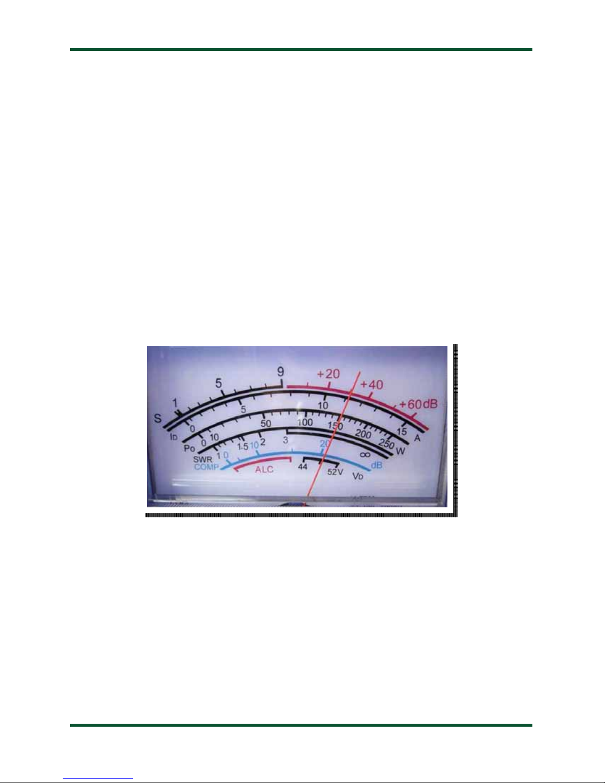
The front panel of the M-7700 shows seven calibrated scales:
S: Received signal strength
•
ID: Final Output Transistors Drain Current (Amps)
•
PO: Transmit power output in watts
•
SWR: Transmit Standing Wave Ratio
•
COMP: Compression ratio, in dB
•
ALC: Auto Level Control
•
: Final Output Transistors Drain Voltage
V
•
D
PAGE 4
Page 5

Back Panel:
The rear panel of the M-7700 has two jacks, a rocker switch, and two access holes for adjustments.
The DC Coax jack accepts a 2.5 x 5.5mm coaxial DC power cable, 12V, 250mA, center positive.
External power is only required if use of the internal backlight is desired. The meter functions correctly
otherwise without it.
The jack marked “Radio” accepts an 1/8” stereo plug, the other end of which plugs into the meter
jack on the IC-7700. If desired, a standard headphone extension cable may be used to place the M-7700
farther from the radio.
The rocker switch is used to turn the internal backlight on and off. It may be desirable to turn off the
internal backlight when attempting to conserve battery power.
The brightness of the backlight may be adjusted with a small flat blade screwdriver. Carefully insert
the screwdriver into the hole labeled “Brightness”, and gently turn the potentiometer left or right until
the desired brightness is achieved.
The full-scale reading may be adjusted by turning the potentiometer marked “FS” on the rear of the
meter. See the section on Calibration for details.
PAGE 5
Page 6

INSTALLATION
The M-7700 is intended for indoor use only; it is not water-resistant. If you use it outdoors, (QSO
Party outdoor barbecue, for example) you must protect it from rain.
Place the M-7700 in a convenient location near the IC-7700. The included cable has a three foot
reach.
The meter jack on the IC-7700 is located on the rear panel, between the DC Out jack and the
External Keypad jack. Plug one end of the included 1/8” stereo cable into the meter jack. Plug the other
end of the cable into the jack marked “Radio” on the rear of the M-7700.
If desired, connect a suitable power supply (12VDC @ 250mA) to the DC Power jack on the rear of
the M-7700, using the supplied 2.5 x 5.5mm center-positive power cable. This power connection
supplies power to the backlight only. If the backlight feature is not desired, simply leave the DC power
unconnected, and the meter will still function normally.
PAGE 6
Page 7

SETUP
Icom included two menu items in the setup menu system of the IC-7700 transceiver, to allow
configuring an external meter such as the M-7700.
Initial Calibration
As shipped from the factory, the M-7700 is calibrated, but may require some adjustment due to
shipping or other factors. When the radio is off, the needle on the M-7700 should rest at the “1:1” line
on the SWR scale. If it does not, insert a flat blade screwdriver into the plastic screw under the meter
face on the front panel of the M-7700. Gently turn the screw in either direction until the needle rests on
1:1.
With the radio on, press the EXIT/SET button on the front of the transceiver several times to get to
the top of the menu system. Next, press the F7 (SET) soft button at the bottom of the screen. The main
settings screen should now be visible.
Next, press the F2 (ACC) soft button. Using the F1 (down) and F2 (up) soft buttons, scroll down
until the External Meter Output item is selected. Rotate the main dial knob until V
displays the output drive transistor voltage, which should be constant at 48 volts.
Press the F1 (down) button one more time to select External Meter Level, and rotate the main dial
knob clockwise until the level is at 100 percent.
Repeatedly press the soft button that is second from the top on the left side of the IC-7700 main
screen (METER) until something other than V
7700 meter should now be showing near 48V on its VD scale.
When the External Meter Output menu selection is set to VD, and the internal meter is not
displaying V
, the M-7700 should indicate 48VDC. If not, insert a flat blade screwdriver into the hole
D
in the rear of the M-7700 marked FS, and gently rotate the potentiometer until the V
7700 reads exactly 48V. 48V is the tick mark in the center of the 44 to 52V V
The meter is now calibrated, and further calibration should not be necessary.
PAGE 7
is selected. This
D
is displayed on the built-in “virtual” meter. The M-
D
scale on the M-
D
scale.
D
Page 8

Meter Parameter Selection
With the transceiver still in the ACC menu, on the External Meter Output item, rotate the main
tuning knob to choose which radio parameter is displayed on the M-7700 during operation. There are
eight options from which to choose:
External Meter Output
Selection
AUTO
S
P
O
SWR
ALC
COMP
V
D
I
D
External meter displays same as internal (“virtual”) meter
Displays signal strength on receive only
Transmit power output (watts)
Voice compression ratio in dB
Final amplifier transistor drain voltage. Nominally 48VDC
Final amplifier transistor drain current.
Meaning
Standing wave ratio
Automatic Level Control
When finished selecting the External Meter Output, press EXIT/SET twice to return to normal
operation. You may return to this menu at any time to select a different parameter to display, as often as
you like.
PAGE 8
Page 9

OPERATION
Operation of the M-7700 is completely transparent. Simply operate the transceiver as usual, and the
M-7700 will display the selected parameters during transmit and receive operation. If the display of
different parameters is desired, simply repeat the Meter Parameter Selection as required.
The M-7700 has a blue backlight that may be turned on or off using the backlight power switch
located on the top rear of the M-7700. The brightness of the backlight may be adjusted by inserting a
screwdriver into the hole marked Backlight on the rear of the M-7700 and turning gently.
APPLICATION NOTES
Base Station Use
The M-7700 may be placed nearly anywhere on the operating desk. The included 1/8” stereo
connection cable provides the ability to place the meter up to several feet away from the transceiver.
Some obvious choices include on top or beside the radio, or near the station computer.
Remote Use
The M-7700 may be placed farther away from the IC-7700 if desired. A standard 1/8” stereo
headphone jack extension cable is all that is required to connect the M-7700 to the external meter jack
on the IC-7700.
Other Applications
LDG designed your M-7700 specifically for the Icom IC-7700 transceiver, and does not recommend
using it in any other application. However, the meter is, in fact, simply a 500 micro-amp meter
movement; the calibration potentiometer allows a range of .5 - 2 mA. If you choose to use it in a
different application, take care not to exceed the maximum current specification; the meter movement
will be damaged or destroyed by current in excess of this specification.
PAGE 9
Page 10

CARE AND MAINTENANCE
The M-7700 tuner is essentially maintenance-free. The outer case may be cleaned as needed with a
soft cloth slightly dampened with household cleaning solution. As with any modern electronic device,
the M-7700 can be damaged by temperature extremes, water, impact, or static discharge.
TECHNICAL SUPPORT
The LDG Customer Support Center staff is ready to answer your product question by telephone and
over the Internet. We know that you will enjoy your product even more knowing LDG is ready to
answer your questions as the need arises.
Our website links you to the on-line Customer Support Center where you can send us a question, do
your own research in the LDG Product Knowledge Books, and read through lists of frequently asked
product questions. LDG regularly updates on-line information so the best on-line support information is
available all day and every day.
The LDG website provides links to product manuals, just in case you lose this one! When you are
thinking about the purchase of other LDG products our website also has complete product specifications
and photographs you can use to help make your purchase decision. Don’t forget the links to all of the
quality LDG Dealers also ready to help you make that purchase decision.
PAGE 10
http://www.ldgelectronics.com
/
Page 11

TWO-YEAR TRANSFERRABLE WARRANTY
Your product is warranted against manufacturer defects in parts and labor for two full years from the
date of purchase. This two-year warranty is also transferable. When you sell or give away your LDG
product give the new owner a copy of the original sales receipt and the two-year warranty goes with the
new owner.
There is no need to complete a warranty card or to register an LDG product. Your product receipt
establishes eligibility for warranty service so save that receipt. Send your receipt with the product
whenever you send your product to LDG for repair. Products sent to LDG without a receipt are
considered requests for out-of-warranty repair.
LDG does not warranty against product damage or abuse. This means that a product failure, as
determined by LDG, to be caused by the customer or by other natural calamity (e.g. lightning) is not
covered under the two-year warranty. Damage can be caused by failure to heed the product’s published
limitations and specifications or by not following good Amateur practice.
OUT OF WARRANTY SERVICE
Any time a product fails after the warranty, LDG wants to help you get it fixed. Send the product to
us for repair. We will determine what needs to be done, and, based on your prior instruction, either
contact you with an estimate or fix it and contact you with a request to pay any repair charges. Please
contact LDG if you have any questions before you send us an out-of-warranty product for repair.
RETURNING YOUR PRODUCT FOR SERVICE
Returning a product to LDG is easy. We do not require a return merchandise authorization. Visit the
Customer Support Center and download the LDG Product Repair Form. On the Repair Form tell the
LDG technicians exactly what happened or didn’t happen and why you believe the product needs
servicing. The technician attempts to duplicate the problem(s) you had based on how well you describe
it so take the time to be accurate and complete.
Ask your shipper for a tracking number or a delivery verification receipt. This way you know the
product arrived safely at LDG. Be sure to give us your email address so our shipper can alert you online
when your product is en-route back to you. Please be assured that our staff makes every effort to
complete repairs ahead of our published wait time. Your patience is appreciated.
Repairs can take six to eight weeks, but are usually faster than this. The most recent information on
returning products for service is found at the LDG Customer Support Center.
Mail your carefully packaged repair with the Repair Form to:
LDG Electronics, Inc.
Attn: Repair Department
1445 Parran Rd
St. Leonard, MD 20685
PAGE 11
 Loading...