

Page 1

AT-200PC
Automatic PC-Controlled
Antenna Tuner
Manual Version 1.0
--- Preliminary ---
LDG Electronics
1445 Parran Road, PO Box 48
St. Leonard MD 20685-2903 USA
Phone: 410-586-2177
Fax: 410-586-8475
ldg@ldgelectronics.com
www.ldgelectronics.com
Page 2

LDG AT-200PC
Automatic Antenna Tuner
Introduction 3
Jumpstart, or “Real hams don’t read manuals!” 3
Specifications 4
Getting To Know Your AT-200PC 5
Installation 7
Hardware Installation 7
Software Installation 9
Operation 10
Auto and Semi-Auto Modes 10
Memory Tuning 10
Operation with provided LDG software 11
Software overview and setup. 11
Software Operation 13
Operation with the N4PY Rig Control Software 16
Application Notes 18
When to use Auto mode 18
MARS/CAP coverage 18
Data Interface 18
Updating your tuner 24
Updating your tuner 24
Troubleshooting 25
Theory Of Operation 27
The LDG AT-200PC 29
About Memory Tuning 30
A word about tuning etiquette 30
Care and Maintenance 30
Technical Support 30
Warranty and Service 30
Feedback 31
2
Page 3

Introduction
Congratulations on selecting the LDG AT-200PC tuner. The PC-controlled AT-200PC provides
fully automatic, any mode antenna tuning across the entire HF range plus 6 meters at power
levels to 250 watts. It will tune dipoles, verticals, Yagis or virtually any coax-fed antenna. It will
match an amazing range of antennas and impedances, far greater than some other tuners you may
have considered. There are no controls or indicators on the tuner itself -- all functions are
controlled by software.
The AT-200PC represents a quantum leap in features and performance. Enhanced tuning
algorithms provide much faster, precise and consistent tuning. Automatic tuning is now available
during transmission, even SSB, and many user-settable options are accessible from the front
panel. The LEDs provide simultaneous readings of power and
SWR, and readouts of internal
states and settings. LDG's design provides instant memory tuning for up to four different antennas
on each of the two antenna ports.
LDG pioneered the automatic, wide-range switched-L tuner in 1995. From its laboratories near
the nation’s capitol, LDG continues to define the state of the art in this field with innovative
automatic tuners and related products for every amateur need.
Jumpstart, or “Real hams don’t read manuals!”
Ok, but at least read this one section before you transmit:
1. Connect the antenna jack on your transceiver to the "Tx" jack on your AT-200PC
tuner using a 50 Ohm coaxial cable jumper of appropriate power handling capability.
2. Connect your 50 Ohm antenna coax lead to the "Ant 1" jack on the back of your AT200PC.
3. Connect your AT-200PC to a source of 11 - 16 volts DC @ 750mA via the 2.5 by 5.5
mm power jack on the back (center positive).
4. Connect the AT-200PC to your PC via an available serial data port.
5. Power up your transceiver and select the desired operating frequency.
6. Run your PC tuner control software and select the appropriate COM port.
1
7. Begin transmitting, any mode
.
8. Click the Tune button on the PC tuner control software.
9. Wait for the tuning cycle to end; stop transmitting.
10. You’re now ready to operate.
1
If using SSB mode, simply speak into the microphone. You can tune while transmitting up to 125 watts if
your transceiver has a “roll-back circuit” to protect it from high SWR. If it does not have a roll-back circuit,
limit power when tuning to 25 watts to avoid damage to your transmitter or transceiver.
3
Page 4

Specifications
y
y
g
f
• 5 to 250 watts SSB and CW. (100 watts on 6M)
• Two position antenna switch with memories for four antennas on each position
• Tuning time: 0.5 to 6 seconds full tune, < 0.1 second memory tune
• Built in frequency counter for memory operation
• Frequency coverage: 1.8 to 54.0 MHz.
• Tunes 6 to 1000 ohm loads (16 to 150 ohms on 6M), 6 to 4000 ohms with optional 4:1
Balun (LDG RBA 4-1)
• For Dipoles, Verticals, Vs, Beams or and Coax Fed Antenna
• Optional external Balun allows tuning of random length, long wire or ladder line fed
antennas
• Field upgradeable via software download
• Power requirements: 11 to 16 volts DC at 750 mA max during tuning
• Enclosure: 8.5 x 6.0 x 2.0 inches
• Weight: 2 pounds
Never install antennas or transmission lines over or near
power lines. You can be seriousl
of the antenna, support or transmission line touches a power
line. Alwa
the nearest power line should be at least twice the len
the longest antenna, transmission line or support dimension.
IMPORTANT SAFETY WARNING
injured or killed if any part
s follow this antenna safety rule: the distance to
th o
4
Page 5
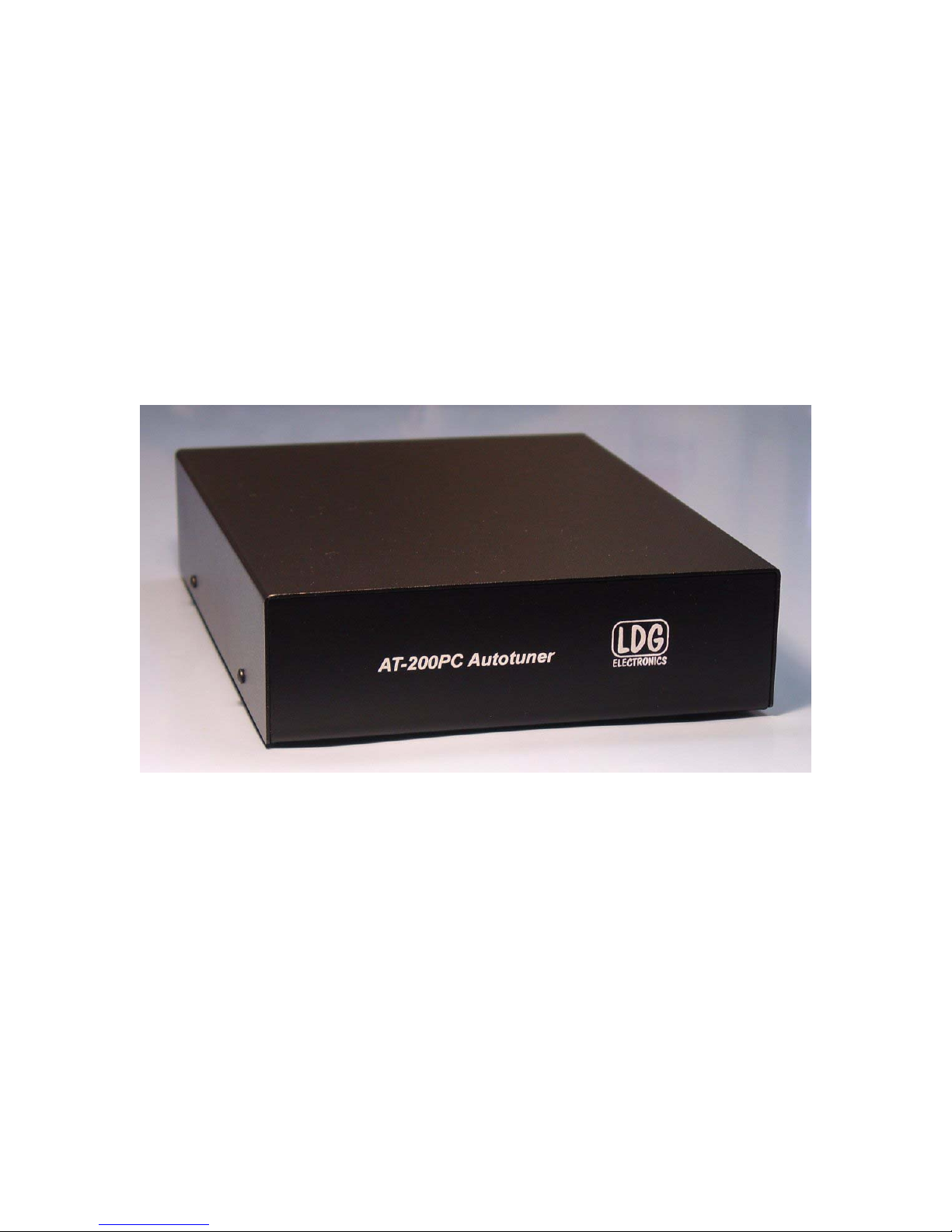
Getting To Know Your AT-200PC
Your AT-200PC is a quality, precision instrument that will give you many years of outstanding
service; take a few minutes to get to know it.
Your AT-200PC can be used with any transceiver or transmitter with coax output operating in the
HF and six meter range at no more than 250 watts output (100 watts on six meters). You can set
the unit to tune automatically whenever the SWR exceeds a set value, or to tune semiautomatically when you start a tuning cycle by pressing the Tune button on the PC user
interface.
The front panel has no controls or readouts. All functions are controlled from a personal computer
interface. You can use any PC and operating system that supports a standard serial or USB port,
including Windows, Linux, Mac OS and others.
The AT-200PC has a total of 16,000 frequency memories. There are 8,000 memories for each of
the two antenna ports, 2,000 tuning settings for each of four separate antennas on each port.
When you transmit near a previously tuned frequency, you can use “Memory Tune” to reset the
tuner in only a fraction of a second. The process of storing tuning data in memory is completely
automatic; your AT-200PC “learns” as you use it, adapting itself to all of the bands and
frequencies you use.
5
Page 6
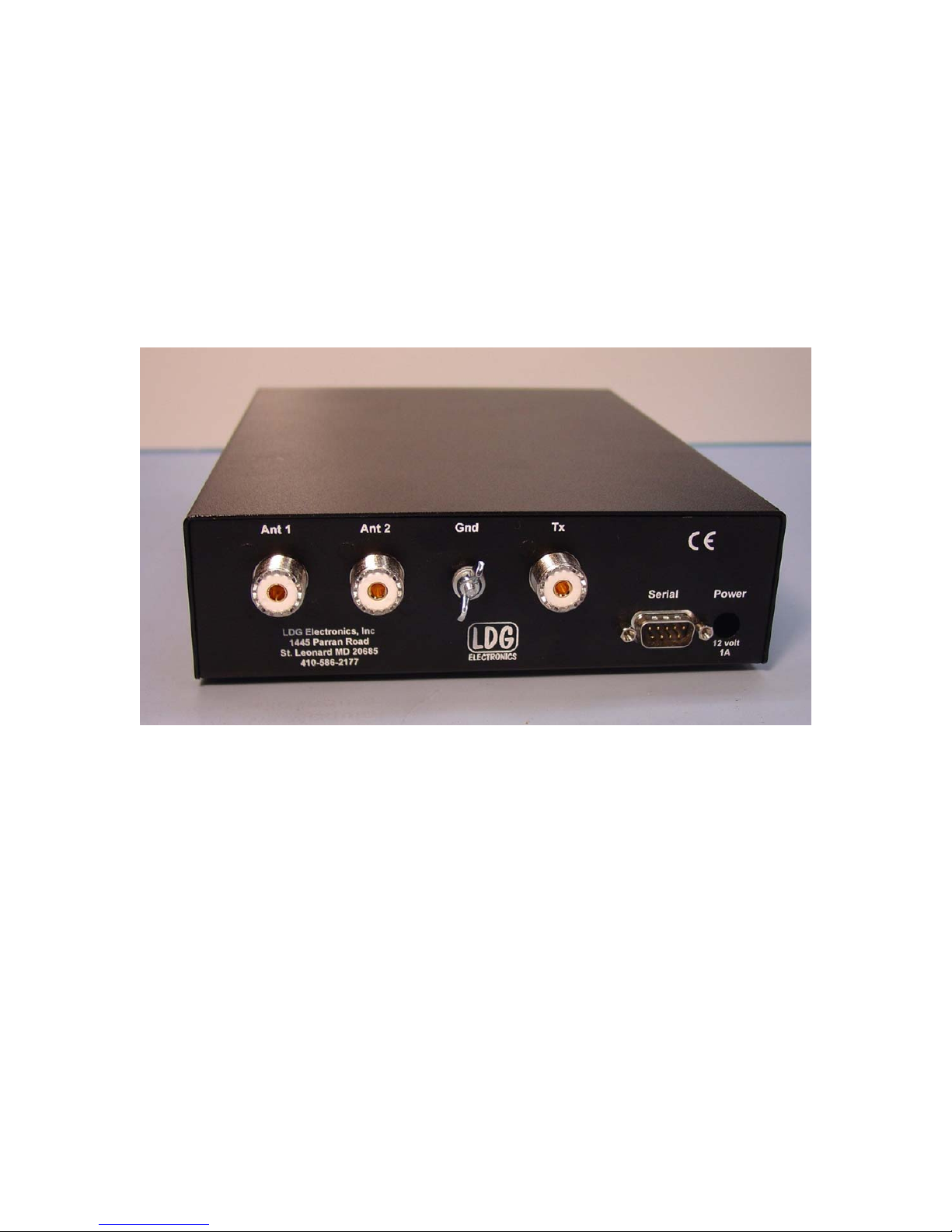
On the back panel, there are six connectors:
RF input (marked “Tx”, standard SO-239 socket)
Antenna connector 1 (marked "Ant 1", standard SO-239 socket)
Antenna connector 2 (marked "Ant 2", standard SO-239 socket)
DC power in (2.5 by 5.5 mm power jack marked "Power", center positive)
DB-9 serial data port marked "Serial" for connecting a control cable to a PC
Ground connector (wing nut)
6
Page 7

Installation
Your AT-200PC tuner is intended for indoor use only; it is not water resistant. If you use it
outdoors (Field Day, for example) you must protect it from rain. The AT-200PC is designed for
use with coax-fed antennas. If you wish to use it with longwires or antennas fed with a balanced
transmission line (e.g., ladder line), an external balun is required; either the LDG RBA-4:1 or
RBA-1:1 is ideal, depending on the antenna and transmission line used.
Hardware Installation
Connect the power supply to the tuner using the provided 2.5 by 5.5 mm coaxial connector. The
power supply must supply 11 - 16 vdc at 750 ma minimum. Best practice is a regulated power
supply, but an unregulated supply can be used if it remains with the specified voltage range under
load.
Connect the HF antenna jack on your transmitter or transceiver to the Tx jack on the back of your
AT-200PC tuner using a coax jumper with standard PL-259 plugs (not provided). Properly
soldered connectors will be far more satisfactory and reliable than crimp-on or “solderless”
connectors. Attach your antenna lead-in coax to either the Ant 1 or Ant 2 jack on the back of your
AT-200PC tuner. You will select the appropriate antenna from the PC control software (see
Operating Instructions).
Grounding your tuner will enhance its performance and safety. LDG recommends that you connect
your tuner to a suitable ground; a common ground rod connected to buried radials is preferred, but
a single ground rod, a cold water pipe can provide a serviceable ground. LDG strongly
recommends that you use a properly installed, high quality lightning arrestor on all antenna cables.
Your AT-200PC can interface directly with most popular PCs. Use a suitable 9-conductor serial
data cable to connect the AT-200PC to an available serial port on your PC. You can also connect
the serial cable to a USB jack on your PC by using the provided adapter. RTS and CTS lines are
required.
If you are using rig control software such as that offered by N4PY, for example, you will make
two serial connections to your PC: one for the radio and one for the tuner. Your AT-200PC is
designed to use a serial port, but in case you don't have a free port, LDG provides you with a
serial-to-USB adapter. This will allow you to connect your AT-200PC to a USB port instead of a
serial port.
In Windows 98 or XP, the USB adapter is a plug-and-play device. Place the included driver CD
in your drive, then plug the adapter into any available USB port on your PC. Follow the
instructions in the New Hardware dialog.
Select "Search for driver"; Windows will find the driver on the CD and install it automatically. If
a security panel informs you that the driver is not certified, select Continue to complete the
installation.
The USB adapter will install itself as the next available COM port. For example, if your PC is
already set for COM1 and COM2, the adapter will be installed as COM3. Thereafter, you can use
it as you would any COM port.
7
Page 8
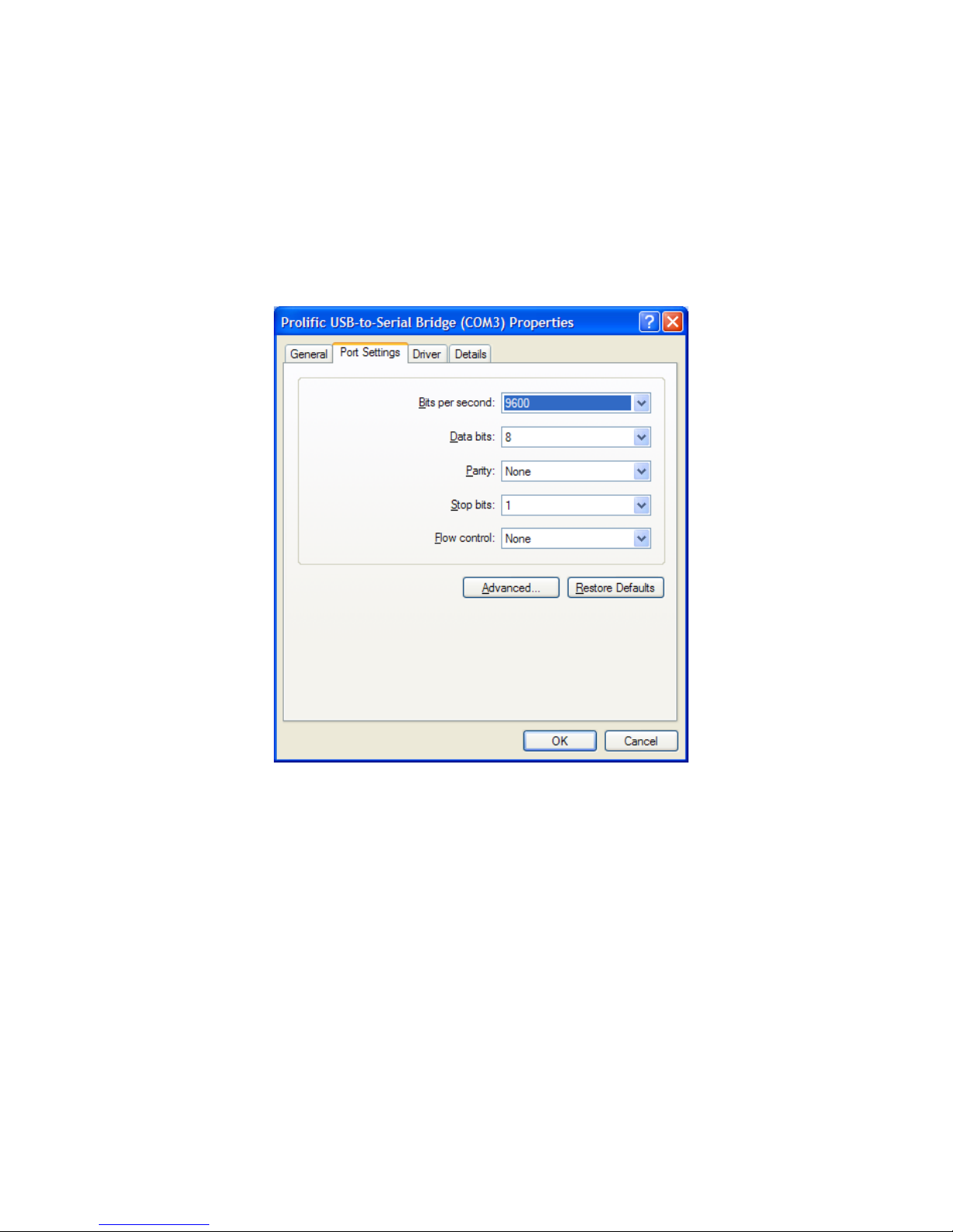
To set serial port parameters for the USB adapter in Windows, select Start > Control Panel >
System, then select the Hardware tab. Select Device Manager, then click on Ports. Double
click on the USB-to-Serial Bridge, then click on the port settings tab. On that panel, you can set
port speed, number of data bits, number stop bits, parity, flow control and other serial parameters.
Set the parameters to 9600 baud, 8 data bits, no parity, 1 stop bit and no flow control. Click OK to
save your settings.
8
Page 9
Software Installation
Your AT-200PC is compatible with several popular rig control programs. Simply follow the
installation instructions that come with the software.
N4PY Rig control software.
All N4PY rig control programs support the AT-200PC. N4PY publishes software for the
following rigs:
• Most Icom transceivers
• Most Kenwood transceivers
• TenTec Orion, Orion II, Pegasus, Jupiter, Argonaut V
• Elecraft K2
See the N4PY web page at www.n4py.com for more details.
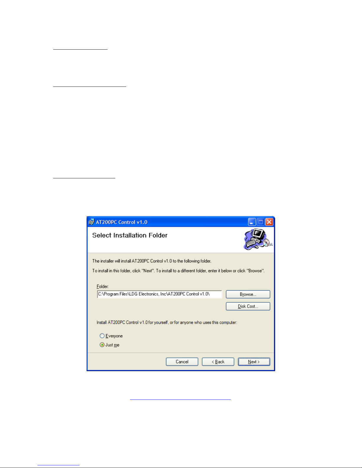
LDG provided software
As a convenience, LDG provides a simple control program to get you started. Download the file
from LDG's web site (http://www.ldgelectronics.com), saving it to your desktop. Execute this
installer program and follow the installation dialog.
The Microsoft .Net Framework version 1.1 must be installed on your PC to run this software.
This is a free download from http://www.microsoft.com/downloads/
9
Page 10

Operation
All tuner functions are controlled through the PC interface. The details of the interface vary
among software products; see your software's documentation for details. Details of the simple
LDG-provided software are below.
Auto and Semi-Auto Modes
In Auto mode the tuner will begin a tuning cycle whenever the SWR exceeds the value you set
(see section on setting autotune threshold in the PC interface). In Semi mode a tuning cycle
begins only when you start one by pressing the Tune button on the PC interface, regardless of
SWR. You can also start a Semi tuning cycle while the tuner is in Auto mode. Your personal
operating practices will determine which mode is best for you.
Auto mode tuning works well while you are transmitting in SSB, AM, CW or any digital mode.
Recent advances in LDG's tuning algorithms allow your AT-200PC to tune effectively even with
a varying RF signal. This means that as you change frequencies, antennas or bands, you don't
have to make a separate tuning transmission; just start talking and your AT-200PC will match up
in as little as 0.2 seconds.
Memory Tuning
Your AT-200PC has frequency memories for four antennas on each antenna port. They store the
tuning parameters for each frequency as you tune. You can use a wide variety of antennas,
connecting them to the two antenna ports as needed. Think of it; you could be using a Yagi,
Quad, Loop or Vee on the Ant A port, and a Dipole, Vertical, Longwire or J-Pole on the Ant B
port, connecting them as needed (or switching them through an external coax switch), and each of
them will have dedicated memories. When you transmit on or near a memorized frequency again,
the tuner finds the best match for that port and antenna and sets those parameters in a fraction of a
second, much faster than a full tuning cycle. This will work best if you always use a particular
antenna on the same antenna port each time.
When you tune, you can select between a Memory tune and a Full tune. If you select Memory
tune and there is no appropriate memory data, the tuner will automatically begin a full tuning
cycle. Tuning parameters are stored in EEPROM memory, and are retained indefinitely, even if
power is removed.
10
Page 11

Operation with provided LDG software
LDG provides you with a simple application program to control your AT-200PC. Please note the
following carefully:
The provided software is "Beta" software, and may contain unknown bugs. It is provided to you
as "Freeware"; it is not part of the price of the tuner. It is provided to you "as is" without
warranty, and LDG provides no support for it. If you have problems or questions about the
software, LDG recommends you consult the LDG users group at http://groups.yahoo.com/ldg.
Software overview and setup.
The software provides a simple graphical user interface to control the tuner. Menu items [1]
provide for configuration. Several data fields [2] show internal tuner states and other related
information. Software pushbuttons [3] and radio buttons [4] control tuner functions.
11
Page 12

With the tuner powered up and connected to your PC via a serial port or the USB serial port
adapter, select the correct serial port from the file menu: File Æ Preferences. A menu of COM
ports will appear:
Click on the appropriate COM port (COM1, for example), the click "Apply". The software will
connect with the tuner, then inform you that the tuner is online. Click OK to continue.
You can configure the tuner using the radio buttons in the center of the user interface.
SWR Thresh: This sets the tuning threshold. The tuner will continue to seek a match until it
reaches the SWR you set. The lower the SWR, the longer it will take the tuner to reach a match.
A setting of 1.5 is usually a good compromise between tuning time and low SWR.
Updates On/Off: When set to on, power, SWR and frequency values are updated in real time
while transmitting.
Antenna Select: You can select either of the two antenna ports with this setting. Never try to
change this setting while transmitting.
Tuner Select: When set to Active, the tuner is in the line, matching the antenna to the transmitter.
When set to Bypass, RF goes directly to the antenna with no matching.
Tuner Mode: In Auto mode, the tuner will automatically begin a tuning cycle an time the SWR
exceeds the threshold you set. In Manual mode, you must start each tuning cycle manually.
12
Page 13

Software Operation
Full Tune: To begin a full tuning cycle, transmit a carrier of at least 5 watts, but not more than
250 watts. A convenient way to do this is to set your transmitter to AM and press the Transmit
switch. This will transmit an unmodulated carrier of 25 - 50 watts depending on your radio.
With RF present, click the Full Tune button on the user interface. The notation "Tuning" appears
in the frequency block, and a full tuning cycle will begin; you will here the relays clicking in the
tuner as it seeks a match.
In a few seconds the cycle will end, with the data blocks in the upper left displaying the
approximate frequency, transmitted power level and achieved SWR. Unkey your transmitter.
You can press Tune before transmitting if you wish; the tune cycle will time out after a few
seconds if no RF is present. If no RF is present, RF is lost during the tune cycle, or the tuner is
unable to achieve an SWR below the maximum you set, an error message will appear.
Memory Tune: As you use your AT-200PC, it automatically memorizes tuning parameters for
rapid recall. You can access these with the Memory Tune button. With RF present, click the
Memory Tune button on the interface. If parameters for the present frequency are available, they
will be reset in a fraction of a second. If no parameters are available, a full tuning cycle will
automatically begin.
13
Page 14

Manual Adjustments: In rare cases, you may want to "tweak" the final tuned setting. You can
manually adjust both the capacitor and inductor setting with the buttons on the left of the user
interface. As you click up and down, the presently selected inductor and capacitor are shown in
the associated data blocks. You can similarly set the Hi and Low Z relay with the radio buttons.
Frankly, you probably won't use these controls very often; your AT-200PC is very good at
finding a match. These controls are included only to provide you with the maximum flexibility in
using your tuner.
Resetting the Tuner: The Reset button in the lower left resets all relays to their neutral position,
effectively putting the tuner in bypass. However, if Automatic mode is selected, a new tuning
cycle will begin when you transmit if the SWR is above the selected threshold.
Store: You can manually store the present tuning parameters at any time with this button.
During transmit, the frequency display turns red:
Other Menu Items:
The utility menu (Utils) contains three useful utility functions:
• Memory Clear: Clears all programming memories. Be careful with this function; clear the
memory only when you're sure you want to start over memorizing tuning parameters.
• Clear Comms: Resets the serial link between your PC and the tuner, and allows you to
reselect the COM port. Try this if your tuner appears "frozen".
• Clear History: Clears the history window on the right.
14
Page 15

The Set menu includes:
Set Inductor: Provides an alternate means to set the inductor to a specific value. Move the slider
to the desired value and then click Ok. You can also set the Hi/Lo Z relay from this panel.
Set Capacitor: Provides an alternate means to set the capacitor to a specific value
Set Frequency: Allows you to manually set the frequency. This controls which stored tuning
parameters are used. Select MHz on the left, the adjust the slider for KHz. When done, click Set
Freq.
15
Page 16

Operation with the N4PY Rig Control Software
N4PY publishes rig control software that is compatible with the AT-200PC
2
. Operation with this
software is shown here as an example of this class of program. To use the software with the tuner,
you will connect your rig to your PC via one serial port (COM1 for example), and the tuner to a
second serial port (COM2 for example). After launching the software, select the Settings menu,
then go to the Preferences 3 menu. Check the box labeled "Using LDG AT-200PC Autotuner",
and select the appropriate COM port from the list.
2
This information is provided as a convenience to our users. LDG does not provide support for the N4PY
or other third-party software.
16
Page 17

On the radio control panel, the tuner controls appear at the lower left.:
1. Auto Tnr: Enables the tuner
2. Byp: Puts the tuner in bypass mode
3. Ant1: Toggles between the two antenna ports on the tuner
4. Cap: Manually adjusts the capacitor setting
5. Ind: Manually adjusts the inductor setting
6. HiZ: Manually toggles between Hi and Low Z setting
7. Sto: Manually stores the present tuning settings
8. Rcl Tnr: Initiates a memory tune
To tune manually, click the Tune button on the N4PY interface while transmitting.
For more information on using the N4PY control program, consult the program's documentation
and help files.
12345678
17
Page 18

Application Notes
When to use Auto mode
Auto mode is most useful when you are often changing frequencies and bands (a contest, for
example). With memory operation, Auto mode will retune almost instantly whenever you
transmit on a new frequency. On the other hand, if your antenna SWR is fairly flat across the
band of frequencies you're using, retuning might not be necessary, and semi-automatic mode
would be preferable.
MARS/CAP coverage
Your AT-200PC provides continuous tuning over its specified range, not just in the ham bands.
This makes it useful for MARS or CAP operation, or any other legal HF operation.
Data Interface
The following information describes the digital dialog that takes place between the PC and tuner.
It is included to allow you to write your own software to control the tuner.
Your AT-200PC communicates with your PC via a serial data interface with the following
parameters:
8 data bits, 1 stop bit, no parity, no flow control, data speed 9600 baud
The Transmit Data, Receive Data, Clear To Send and Ready To Send lines must be connected.
The RTS line must be asserted (positive going) for 3 milliseconds and then de-asserted for 1
millisecond before sending each command; this "wakes up" the tuner to receive the command.
Your AT-200PC is capable of accepting 37 different commands, and responding with 19 data
replies. Each command is in the following four-byte format:
Preamble Command Parameter 1 Parameter 2
Each part is one byte long. The Preamble byte is always 165 decimal ($A5 hex). The Command
byte specifies which of the 37 commands is being sent. Most commands have no parameters; two
have one parameter, and one command uses both parameters. Even when not used, the parameters
must be sent to the tuner; values are ignored but must be present -- zero works fine in these cases.
Unused parameters are omitted from the definitions below, but must always be present as zeros in
the data.
Responses from the tuner are in the same format. Unused parameters may in fact contain nonzero data, but it is meaningless and the PC application should ignore it. If a parameter is not listed
in for a response code, its content should be ignored.
The following descriptions provide a brief summary of commands and responses. A more
complete and detailed description of the protocol is available for download from the LDG web
site.
18
Page 19

AT-200PC Commands
No Operation, Command code 0. This is a dummy command that produces no change in the
tuner.
Inductor Up, Command code 1. Increases inductance value by one unit.
Inductor down, Command code 2. Decreases inductance value by one unit.
Capacitor Up, Command code 3. Increases capacitance value by one unit.
Capacitor Down, Command code 4. Decreases capacitance value by one unit.
Memory Tune, Command code 5. Starts a memory tuning cycle. Automatically defaults to full
tune if no stored tuning parameters are available.
Full Tune, Command code 6. Starts a full tuning cycle even if stored tuning parameters are
available.
Set impedance range relay to High, Command code 8. Sets the Hi-Low Z range relay to the High
setting.
Set impedance range relay to Low, Command code 9. Sets the Hi-Low Z range relay to Low.
Select Antenna 1, Command code 10. Selects Antenna 1 on the internal antenna switch.
Select Antenna 2, Command code 11. Selects Antenna 2 on the internal antenna switch.
Update setting data, Command code 40. Requests the tuner to send updated data on the current
state of all tuning relays.
Request version number, Command code 41. Requests the tuner to send its product ID and
firmware version number
Arm memory clear, Command code 42. Enables clearing memory if the next command is Clear
Memory.
Clear memory, Command code 43. Clears EEPROM memory if the previous command was Arm
Memory Clear
Standby, Command code 44. Places the tuner in standby mode.
Activate, Command code 45. Takes tuner out of standby mode.
Store tuning parameters, Command Code 46. Stores the current tuning parameters for the present
frequency.
19
Page 20

Set SWR threshold, Command code 50 - 56. Set the threshold for a "good" tune to SWR values
between 1.1 and 3.0. Tunes ending at SWR values above the threshold will not be saved to
memory.
Command Code SWR Threshold
50 1.1
51 1.3
52 1.5
53 1.7
54 2.0
55 2.5
56 3.0
Reset relays, Command code 57. Resets all L, C and the Hi/Lo Z relays.
Automatic tuning on, Command code 58. Sets automatic tuning on.
Automatic tuning off, Command code 59. Sets automatic tuning off.
Request forward power, Command code 60. Requests tuner to report the forward RF power.
Request reflected power, Command code 61. Requests tuner to report the reflected RF power.
Request SWR, Command code 62. Requests tuner to report the SWR.
Turn live updates on, Command code 63. Turns live updates on if previous turned off.
Turn live updates off, Command code 64. Disable live updates of forward and reflected power,
SWR and frequency (defaults to On at power up).
Set inductor value, Command code 65. Parameter 1: inductor value 0 - 127. Manually sets
inductor values.
Set capacitor value, Command code 66. Parameter 1: capacitor value 0 - 127. Manually sets
capacitor values.
20
Page 21

Request tuner settings for a specified frequency, Command code 67. Parameter 1: frequency,
most significant digit, Parameter 2: frequency, least significant digit. Requests the tuner to return
the tuner parameters for a specified frequency. Frequency expressed as period in "tick" units of
0.8 µSec. Valid values of period range from 370 ticks (55.3 MHz) to 11593 ticks (1.76 MHz).
A shortcut for determining the period value from the desired operating frequency in MHz is
Period = 20,480 / Freq
So, for example to set 14.230 MHz:
Period = 20,480 / 14.230 = 1439
Most significant byte (1439) = 0x05
Least significant byte (1439) = 0x9F
So, the command would be sent as: 0x43 0x05 0x9F
Request memory dump, Command code 68. Requests the tuner to dump all EEPROM settings.
See application notes for details.
21
Page 22

AT-200PC responses
No operation, Response code 00. No Operation. Also sent to indicate AT200PC has woken up
Inductor value, Response code 01. Parameter 1: Value 0-127. Present inductor value.
Capacitor value, Response code 02. Parameter 1: Value 0-127. Present capacitor value.
Hi/Lo relay setting, Response code 03. Parameter 1: 0 or 1. Present Hi/Lo relay setting.
Antenna port setting, Response code 04. Parameter 1: 0 or 1, showing present antenna selection.
0 indicates port 1, 1 indicates port 2.
Forward power, Response code 05. Parameter 1: most significant digit, Parameter 2: least
significant digit. Forward in hundredths of watts, I.e. a value of 1000 indicates 10.0 watts
Reverse power, Response code 18. Parameter 1: most significant digit, Parameter 2: least
significant digit. Reflected Power, in hundredths of watts.
SWR, Response code 06. Parameter 1: none, Parameter 2: SWR, as 256ρ
2
, where ρ is the factor in
the classic SWR equation:
To calculate the SWR value from response code 06, simply divide the value in the second
parameter by 256, take the square root of the quotient, then compute the SWR from the above
equation
Tuned frequency, Response code 07. Parameter 1: most significant byte, Parameter 2: least
significant byte. The two parameters form a 16 bit word that represents one half of the period of
the transmitted frequency, divided by 32,768, in units of 0.8 µSec. No, really.
For example, if the value reported is 471, then Period = 471 × 0.8µSec = 3.768 × 10
this is the half-period, so the actual period is: 3.768 × 10
−4
Sec × 2 = 7.536 × 10
−4
−4
Sec. But
Sec. Thus, the
frequency is:
Freq =1 / 7.536 × 10
−4
= 1326.9 Hz.
However, the frequency counter on the AT200PC internally divides the incoming frequency by
32,768 before measuring it, so you must then multiply the result by 32,768 to get the actual
frequency value. Thus Freq = 1326.9 × 32, 768 = 43,481,953 Hz = 43.481953 MHz.
Tune succeeded, Response code 09. Indicates that the requested tuning operation
succeeded.
22
Page 23

Tune failed, Response code 10. Parameter 1: Reason 0-2. Indicates that the requested tuning
operation failed.
Parameter 1 Value: Failure Reason:
00 No RF was detected.
01 RF Carrier was lost before the tune completed.
02 The tuner was unable to bring the SWR down
below the SWR Threshold.
Version information, Response code 11. Parameter 1: Produce ID, Parameter 2: Major/Minor
version number.
Clear done, Response code 12. Indicates that the EEPROM erase operation has completed.
In standby mode, Response code 13. Indicates that the tuner has been placed in standby mode.
In active mode, Response code 14. Indicates that the tuner has restored the settings that were
saved prior to entering standby mode.
Store OK, Response code 15. Indicates that the requested store to memory operation has
completed. Note that this will be indicated whether the store operation failed or succeeded.
SWR threshold, Response code 16. Parameter 1: Threshold 0-6. Indicates the currently active
SWR threshold used for tuning.
Byte 2, SWR Threshold value
0 = 1.1:1
1 = 1.3:1
2 = 1.5:1
3 = 1.7:1
4 = 2.0:1
5 = 2.5:1
6 = 3.0:1
Auto status, Response code 17. Parameter 1: 0 or 1Report Auto Tune setting. 0 = disabled, 1 =
enabled.
Live update status, Response code 19. Parameter 1: 0 or 1. Indicates Live Update on or off. 0 =
disabled, 1 = enabled.
23
Page 24

Updating your tuner
The firmware in your tuner can be updated by running an update utility provided by LDG. This
will give you access to the latest features and performance enhancements. You will download two
files from the LDG web site: the updater program, and the update hex file.
1. Download the updater program from the LDG web site. Unzip the file to your desktop (or
any other convenient folder), and run the setup program. Follow the installation
instructions. The default install file is:
c:\ldgelectronics,Inc\AT200OPCFirmwareDownloader
2. Download the update file; these have a .hex file type.
3. Run the updater program.
4. Click the "COM?" button to select the COM port. Select the appropriate port and click
Apply.
5. Click the "Load File" button, then navigate to the .hex file you downloaded, and select it.
6. Click "Send To Tuner" to load the file into the tuner.
7. As the file loads, each line of hex code is displayed in the loader window. Present
releases contain upwards of 1,000 lines of code.
24
Page 25

8. The loader will indicate "Done!" when the code has been successfully loaded.
9. Click OK to dismiss the "Download Succeeded" notice.
10. Click Quit to exit the loader program.
11. Power cycle the tuner by disconnecting, then reconnecting DC power; your new firmware
is up and running.
25
Page 26

Troubleshooting
12.
There are two LEDs inside the tuner that can be helpful in troubleshooting. Remove the screws
on the sides of the tuner, and carefully remove the top.
Exercise extreme caution when using the tuner with the cover removed: high RF voltages
may be present during operation. Touch no part inside the tuner while transmitting!
• On reset, the LEDs blink green - red - green. In normal operation you should see this only
at power-up.
• The green LED lights when the unit receives a serial interrupt and "wakes up", then goes
off when the unit goes back to "sleep". In normal operation, the green LED will blink on,
then off with each serial command.
• The red LED lights when RF is present. It goes off when the unit goes back to sleep.
• The green LED pulses on and off during a memory clear.
26
Page 27

Theory Of Operation
Some basic ideas about impedance
The theory underlying antennas and transmission lines is fairly complex, and in fact employs a
mathematical notation called “complex numbers” that have “real” and “imaginary” parts. It is
beyond the scope of this manual to present a tutorial on this subject
3
, but a little background will
help you understand what your AT-200PC is doing, and how it does it.
In simple DC circuits, the wire resists the current flow, converting some of it into heat. The
relationship between voltage, current and resistance is described by the elegant and well-known
“Ohm’s Law”, named for Georg Simon Ohm of Germany, who first discovered it in 1826. In RF
circuits, an analogous but far more complicated relationship exists.
RF circuits also resist the flow of electricity. However, the presence of capacitive and inductive
elements causes the voltage in the circuit to lead or lag the current, respectively. In RF circuits
this resistance to the flow of electricity is called “impedance”, and can include all three elements:
resistive, capacitive, and inductive.
Capacitive
Reactance
Inductive
Reactance
The output circuit of your transmitter consists of inductors and capacitors, usually in a
series/parallel configuration called a “pi network”. The transmission line can be thought of as a
long string of capacitors and inductors in series/parallel, and the antenna is a kind of resonant
circuit. At any given RF frequency, each of these can exhibit resistance, and impedance in the
form of capacitive or inductive “reactance”.
Transmitters, transmission lines, antennas and impedance
The output circuit of your transmitter, the transmission line, and the antenna all have a
characteristic impedance. For reasons too complicated to go into here, the standard impedance is
about 50 ohms resistive, with zero capacitive and inductive components. When all three parts of
the system have the same impedance, the system is said to be “matched”, and maximum transfer
of power from the transmitter to the antenna occurs. While the transmitter output circuit and
transmission line are of fixed, carefully designed impedance, the antenna presents a 50 ohm, nonreactive load only at its natural resonant frequencies. At other frequencies, it will exhibit
capacitive or inductive reactance, causing it to have an impedance different from 50 ohms.
When the impedance of the antenna is different from that of the transmitter and transmission line,
a “mismatch” is said to exist. In this case, some of the RF energy from the transmitter is reflected
from the antenna back down the transmission line, and into the transmitter. If this reflected
energy is strong enough it can damage the transmitter’s output circuits.
The ratio of transmitted to reflected energy is called the “standing wave ratio”, or SWR. An SWR
of 1 (sometimes written 1:1) indicates a perfect match. As more energy is reflected, the SWR
3
For a very complete treatment of this subject, see any edition of the ARRL Handbook for Radio
Communications (previously the Handbook For Radio Amateurs)
27
Page 28

rises to 2, 3 or higher. As a general rule, modern solid state transmitters must operate with an
SWR of 2 or less. Tube exciters are somewhat more tolerant of high SWR. If your 50 ohm
antenna is resonant at your operating frequency, it will show an SWR close to 1. However, this is
usually not the case; operators often need to transmit at frequencies other than resonance,
resulting in a reactive antenna and a higher SWR.
SWR
=
+
FR
where F = Forward power (watts), R = Reflected power (watts)
FR
/1/1−
SWR is measured using a device called an “SWR bridge”, inserted in the transmission line
between the transmitter and antenna. This circuit measures forward and reverse power from
which SWR may be calculated (some meters calculate SWR for you). More advanced units can
measure forward and reverse power simultaneously, and show these values and SWR at the same
time.
An antenna tuner is a device used to cancel out the effects of antenna reactance. Tuners add
capacitance to cancel out inductive reactance in the antenna, and vice versa. Simple tuners use
variable capacitors and inductors; the operator adjusts them by hand while observing reflected
power on the SWR meter until a minimum SWR is reached. Your LDG AT-200PC automates
this process.
No tuner will fix a bad antenna. If your antenna is far from resonance, the inefficiencies inherent
in such operation are inescapable; it’s simple physics. Much of your transmitted power may be
dissipated in the tuner as heat, never reaching the antenna at all. A tuner simply “fools” your
transmitter into behaving as though the antenna were resonant, avoiding any damage that might
otherwise be caused by high reflected power. Your antenna should always be as close to
resonance as practical.
Forward Power (Watts)
20 30 40 50 60 70 80 90 100
2 1.92 1.70 1.58 1.50 1.45 1.41 1.38 1.35 1.33
4 2.62 2.15 1.92 1.79 1.70 1.63 1.58 1.53 1.50
6 3.42 2.62 2.26 2.06 1.92 1.83 1.75 1.70 1.65
8 4.44 3.14 2.62 2.33 2.15 2.02 1.92 1.85 1.79
10 5.83 3.73 3.00 2.62 2.38 2.22 2.09 2.00 1.92
12 7.87 4.44 3.42 2.92 2.62 2.41 2.26 2.15 2.06
14 11.24 5.31 3.90 3.25 2.87 2.62 2.44 2.30 2.20
16 17.94 6.42 4.44 3.60 3.14 2.83 2.62 2.46 2.33
Reflected Power (Watts)
18 37.97 7.87 5.08 4.00 3.42 3.06 2.80 2.62 2.47
20 - 9.90 5.83 4.44 3.73 3.30 3.00 2.78 2.62
22 - 12.92 6.74 4.94 4.07 3.55 3.21 2.96 2.77
24 - 17.94 7.87 5.51 4.44 3.83 3.42 3.14 2.92
26 - 27.96 9.32 6.17 4.85 4.12 3.65 3.32 3.08
28 - 57.98 11.24 6.95 5.31 4.44 3.90 3.52 3.25
30 - - 13.93 7.87 5.83 4.79 4.16 3.73 3.42
32 - - 17.94 9.00 6.42 5.18 4.44 3.95 3.60
34 - - 24.63 10.40 7.09 5.60 4.75 4.19 3.80
36 - - 37.97 12.20 7.87 6.07 5.08 4.44 4.00
38 - - 77.99 14.60 8.80 6.60 5.44 4.71 4.21
40 - - - 17.94 9.90 7.19 5.83 5.00 4.44
42 - - - 22.96 11.24 7.87 6.26 5.31 4.68
44 - - - 31.30 12.92 8.65 6.74 5.65 4.94
46 - - - 47.98 15.08 9.56 7.27 6.02 5.22
48 - - - 97.99 17.94 10.63 7.87 6.42 5.51
50 - - - - 21.95 11.92 8.55 6.85 5.83
SWR Lookup Table
Find SWR at intersection of
forward power column and
reflected power row
.
28
Page 29

The LDG AT-200PC
In 1995 LDG pioneered a new type of automatic antenna tuner. The LDG design uses banks of
fixed capacitors and inductors, switched in and out of the circuit by relays under microprocessor
control. A built-in SWR sensor provides feedback; the microprocessor searches the capacitor and
inductor banks, seeking the lowest possible SWR. The tuner is a “Switched L” network consisting
of series inductors and parallel capacitors. LDG chose the L network for its minimum number of
parts and its ability to tune unbalanced loads, such as coax-fed dipoles, verticals, Yagis; in fact,
virtually any coax-fed antenna. The inductors are switched in and out of the circuit by relays
controlled by the microprocessor. An additional relay switches between high and low impedance
ranges.
The capacitors are connected to ground with the seven inductor relays. Another relay switches the
entire capacitor bank to the input or output side of the inductor. This switching allows the AT200PC to automatically handle loads that are greater than 50 ohms (high setting) and less than 50
(low setting). All of the relays are sized to handle over 300 watts continuously.
The SWR sensor is a variation of the Bruene circuit. This SWR measuring technique is used in
most dual-meter and direct-reading SWR meters. Slight modifications were made to the circuit to
provide voltages (instead of currents) for the analog-to-digital converters (ADCs) that provide
signals proportional to the forward and reverse power levels. The single-lead primary through the
center of the sensor transformer provides RF current sampling. Diodes rectify the sample and
provide a dc voltage proportional to RF power. Variable resistors calibrate the FORWARD and
REVERSE power levels. Once adjusted, the forward and reverse power sensors produce a
calibrated DC voltage proportional to the forward and reverse RF power levels. These two
voltages are read by the ADCs in the microprocessor. Once in a digital format, the they are used
to calculate SWR in real time.
Although the microprocessor’s oscillator runs at 20 MHz. The main tuning routine takes about 75
cycles to make a tuner adjustment and take a new SWR measurement, or 7 milliseconds per tuner
adjustment. If running at maximum speed, the microprocessor can try all inductor-capacitor
combinations in under 3 seconds. Unfortunately, the mechanical relays can’t react as quickly as
the microprocessor, and the tuning speed must be slowed down to compensate for relay settling
time.
The tuning routine, written in assembly language, uses an algorithm to minimize the number of
tuner adjustments. The routine first de-energizes the high/low impedance relay if necessary, then
individually steps through the inductors to find a coarse match. With the best inductor selected,
the tuner then steps through the individual capacitors to find the best coarse match. If no match is
found, the routine repeats the coarse tuning with the high/low impedance relay energized. The
routine then fine tunes the capacitors and inductors. The program checks LC combination to see if
a 1.5 or lower SWR can be obtained, and stops when it finds a good match.
The microprocessor runs a fine tune routine just after the tuner finds a match at an SWR of 1.5 or
less. This routine tries to get the SWR as low as possible (not just 1.5); it takes about a half
second to run. There is also a quick tune mode. If the swr is below 2.0 when you press the tune
button to start a tuning cycle, the tuner will first try a memory tune routine to see if it can achieve
a low swr without a complete re-tune. This also takes about a half second to run. If it does not
find a good match, then it runs a full tuning routine.
29
Page 30

About Memory Tuning
The tuning range of the AT-200PC is divided into 2,000 frequency steps. The steps are smaller at
lower frequencies where antennas are usually more reactive and frequency sensitive, and larger at
higher frequencies. Each time you transmit, the tuner measures the frequency and selects the
appropriate frequency step. There are four memories for each frequency step on each antenna
port. If the tuning parameters are the same as one of the four existing memories for that frequency
and port, they are not stored. If different, they replace one of the existing sets of parameters. In
this way, up to four different antennas can be used on each of the two ports.
When you transmit on a new frequency, the tuner tries all four sets of tuning parameters for that
frequency and port. If it finds a match among the four, it sets those parameters. If not, the tuner
completes a full tuning cycle, storing the new parameters for that frequency and port. As you use
your tuner, it literally learns the performance of up to four antennas on each of the two ports,
storing their tuning parameters for virtually instant re-use.
A word about tuning etiquette
Be sure to use a vacant frequency to tune. With today’s crowded ham bands, this is often difficult.
However, do your best to avoid interfering with other hams as you tune. Your AT-200PC’s very
short tuning cycle, often only a fraction of a second, minimizes the impact of your tuning
transmissions. Tune at reduced power whenever possible; one or two watts is plenty.
Care and Maintenance
Your AT-200PC tuner is essentially maintenance-free; just be sure to observe the power limits
discussed in this manual. The outer case may be cleaned as needed with a soft cloth slightly
dampened in household cleaning solution. As with any modern electronic device, your AT-200PC
can be damaged by temperature extremes, water, impact or static discharge. LDG strongly
recommends that you use a good quality, properly installed lightning arrestor in the antenna lead.
Technical Support
We are happy to help you with your AT-200PC. Telephone technical support is available at 410586-2177 weekdays from 9 am to 5pm Eastern Time. Inquiries by Fax at 410-586-8475 are
welcome, and prompt e-mail support is available at ldg@ldgelectronics.com.
Warranty and Service
Your AT-200PC is warranted against defects in parts or workmanship for two years from
purchase. The warranty does not cover damage due to abuse or exceeding specifications. This
warranty applies to the original purchaser only; it is not transferable. A copy of the receipt
showing the purchaser’s name and the date of purchase must accompany units returned for
warranty service. All returns must be shipped to us pre-paid; we will not accept units with
postage due. A return form is provided on our web site for your convenience.
If you need to return your AT-200PC to us for service, package it carefully, keeping in mind that
we will re-use your packaging to return the unit to you. Download the return form from our web
site, fill it out and return it with your tuner. A self-addressed return-shipping label, while not
required, will help insure speedy and accurate delivery of your repaired unit. Include a full
30
Page 31

description of the problem, along with your name, address and a phone number or e-mail address
where we can reach you with any questions. Repairs average about 3 to 6 weeks.
We will be glad to service your AT-200PC after the warranty period has ended. We will notify
you of repair charges by phone or e-mail, and bill you after repairs are completed.
Feedback
If you have an idea to improve our software or hardware, please send us a description. If we
incorporate your idea in the AT-200PC, we'll send you a free upgrade as a “thank you”.
We encourage everyone who uses the AT-200PC to contact us (card, letter or e-mail preferred)
telling us how well it works for you. We are also always looking for photographs of our products
in use; we frequently place such pictures on our Web site (www.ldgelectronics.com).
31
 Loading...