

Page 1

The AT-11 Accessory Interface ACC-11
The AT-11 Accessory Interface (ACC-11) adapter can be installed to allow the owner's of
ICOM IC-706 radios to activate the tuning sequence from the front panel of their radio via
the tune button. The adapter comes with a 6 foot cable to connect to the IC-706.
Also, the ACC-11 can be installed to allow use of the Rem ote Control Head designed for
the AT-11MP. This small control box allows the operator to mount the AT-11 in a remote
location... in the trunk, outside on the tower, etc. The remote head provides control of the
tuning process, including tune activation, mode control, capacitor and inductor switches
for manual control. 2 LEDs indicate tune in progress and tuned SWR at less then 1.5:1.
The remote head is available separately in kit and assembled form. The Remote Head
includes a 10 foot cable. The cable is a Female to Female shielded DB-9 and all 9 wires
are used. The cable can be extended to over 100 feet.
The AT-11 Accessory Interface installed in a Version 2.4 tuner.
The ACC-11 includes one assembled PC board and three cable assemblies. The 14 pin
IDC to 14 pin IDC ribbon cable is used to interface from the AT-11 PC board to the ACC11 PC board. The 10 pin IDC to Male DB-9 ribbon cable is used to interface from the
ACC-11 to the Remote Head. The separate 6 foot cable, a stereo 1/8 plug to a 4 pin
Molex, is to interface between the AT-11 and the IC-706.
Page 2

The interface requires a .250 inch hole be drilled on the back panel of the AT-11. This
hole will be used for the 706 interface attachment cable. The stereo jack is mounted as
shown in the photo below.
Mounting position of 706 connection.
Installing the AT-11 Interface Accessory in an AT-11 2.0, 2.1, 2.4 or 2.5.
Disconnect
the ribbon cable going to the front panel buttons and LEDs. Connect that cable to J3 of
the ACC-11. Be sure to notice the polarity of the connections. Pin 1 is marked on the
ACC-11.
Using the supplied 14 pin IDC ribbon cable, connect one end to J1 of the ACC-11 and the
other to end to J3 of the AT-11. Be sure to notice the polarity of the connections. Pin 1 is
marked on the ACC-11.
If the remote head will be used, connect the 10 pin IDC ribbon cable to J2 of the ACC-11.
The other end will exit the tuner at the top of the chassis near the back of the tuner. Be
care not to overtighten tighten the lid when re-installing to prevent damaging the ribbon
cable.
Page 3

Installing the AT-11 Interface Accessory in an AT-11 2.4 or 2.5.
cable going to the AT-11 front panel PC board. Connect that cable to J3 of the ACC-11.
Be sure to notice the polarity of the connections. Pin 1 is marked on the ACC-11.
Using the supplied 14 pin IDC ribbon cable, connect one end to J1 of the ACC-11 and the
other to end to J3 of the AT-11. Be sure to notice the polarity of the connections. Pin 1 is
marked on the ACC-11. The AT-11 V2.5 will require a twist in the ribbon cable for this
connection.
If the remote head will be used, connect the 10 pin IDC ribbon cable to J2 of the ACC-11.
The other end will exit the tuner at the top of the chassis near the back of the tuner. Be
care not to overtighten tighten the lid when re-installing to prevent damaging the ribbon
cable.
Disconnect the ribbon
Once installed, the AT-11 will work with the tu ne button on the front panel of the IC-706.
The 706 may need to powered off, then back on to recognize the tuner’s presence.
Pressing and holding the 706 tune button will cause the 706 to switch to CW mode,
transmit 10 watts and send a tune signal to the AT-11. The tuner will find the best match
and send a signal back to the 706 when it is finished. The 706 will stop transmitting and
return to previous mode. It is best to leave the AT-11 in the Semi mode when being used
with an IC-706.
The interface to the remote head will work as described in the remote head manual.
Basically, all functions (except power) from the front panel of the AT-11 are duplicated on
the remote head.
Page 4
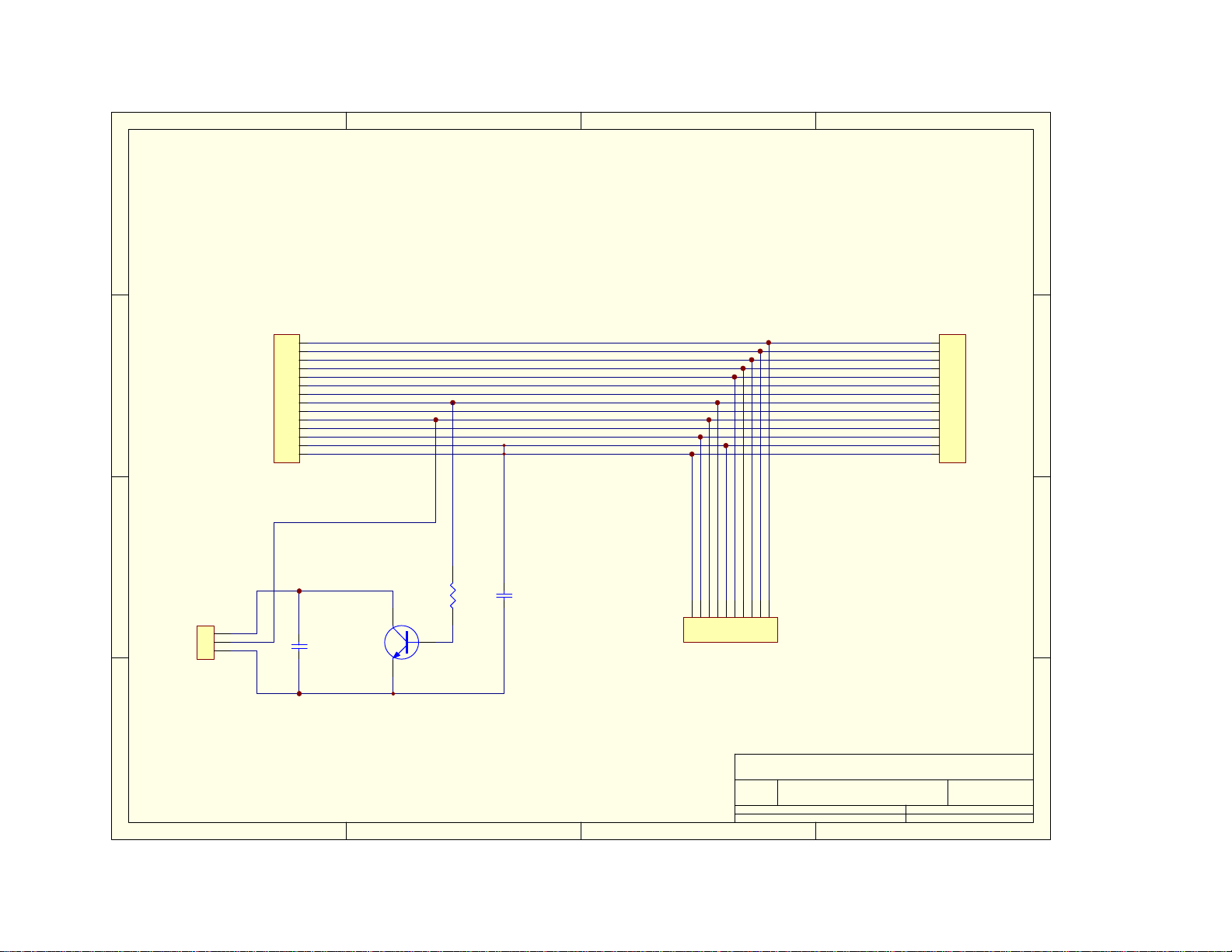
4321
D
J1
CAPUP
1
INDUP
2
CAPDN
3
INDDN
4
GREEN
5
YELLOW
10
11
12
13
14
6
7
8
9
AT-11
C1
.01uf
RED1
RED2
+12IN
TUNE
+12OUT
AUTO
GND
GND
(Tuning)
Q1
2N3904
R1
10K
C2
.01uf
10
J2
Remote
123456789
C
B
J4
TIP (Red)
1
Ring (Yellow)
2
Ground (Black)
3
IC706
J3
1
2
3
4
5
6
7
8
9
10
11
12
13
14
FrontPanel
D
C
B
A
1 2 3 4
Title
ACC-11 Tuner Interface
Number RevisionSize
Letter
Date: 17-Dec-2000 Sheet of
File: C:\Ldg\Genes_Protel_Files\Protel99SE\IC706\IC706.ddbDrawn By:
Version 3.01G
1 1
Glennster, KE3MF
A
 Loading...