

Page 1
02/18-W2013-Wei
- The device is appropriate for in ter ior use only!
7 8 9 10 11 12
4
3
1
5
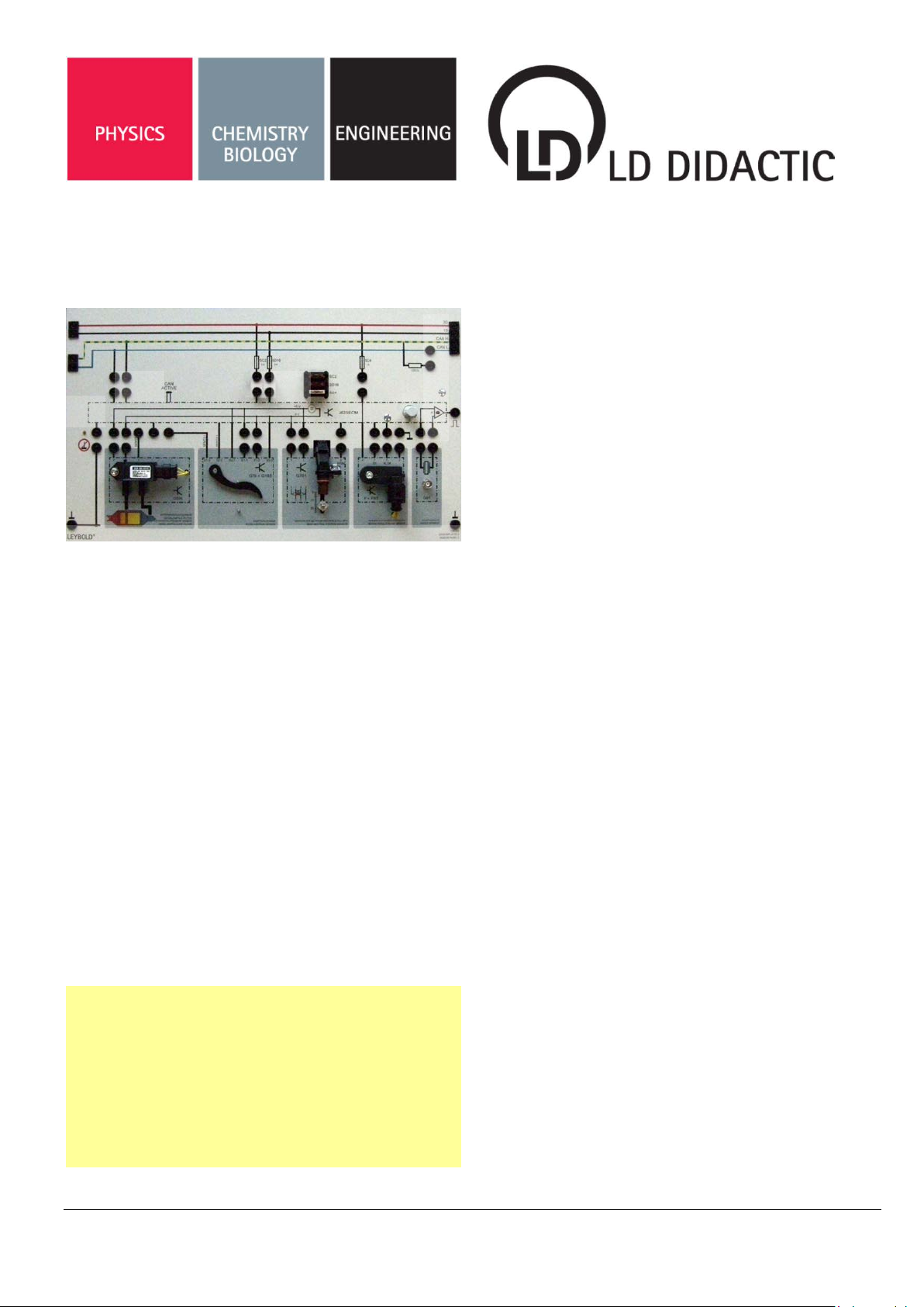
1 Description
This device is used to examine the operation of various
analog and digital sensors.
The device is equipped with original sensors for monitoring
the differential pr essure of a DPF as well as for detec ting
the position of the acc elerator pedal, the neutral position
of the transmission, and the brake pedal. The knocking
sensor 739 03 can also be c onnected to it. The device is
intended for use in educati onal institutions. Use in a r eal
vehicle (including use of individual components) is not permitted.
Safety Note
- Use only safety bridging plugs and safety connection leads!
- Be careful not to short-circuit the power supply.
Fire hazard!
- The device should only be used for training purposes. Installation in an actual vehicle is prohibited!
LD DIDACTIC GMBH • Leyboldstrasse 1 • D-50354 Hürth • Phone (02233) 604-0 • Fax (02233) 604-222 • E-Mail: info@ld-didactic.de
© by LD Didactic GmbH Printed in the Federal Republic of Germany
Technic al alterations reser ved
Instruction Manual 739 708
Sensor Panel 2
2
6
1 Connections Plus Terminal 30 and Terminal 15
2 Slot for CAN Terminating Resis tance STE
120 Ω
3 Connections and Fuses
4 Connection Socket CAN H and CAN L
5 Display for a Lack of Short-circuit to Ground
6 Sensitivity Adjustment and Output Signal for
the Knocking Sensor with Display
7 Short-circuit to ground Terminal 31
8 Sensor for Low Pressure
9 Sensor for Accelerator Position
10 Sensor for the Neutral Position of the Transmis-
sion
11 Sensor for Brake Pedal
12 Connection for Knocking Sensor
2 Scope of the delivery
Sensor panel 2, 739 708
Not included, but recommended accessory equipment:
• Set of 10 magnets 689 0815
• CAN-Databus-Multi-Adapter 773 961
• Knocking sensor 739 03
• PVC tubing, 7 mm diam., 1 m 667 193
• Hand vacuum pump 375 58
• Automotive fault simulator 738 491
• Connecting leads, set of 7 739 195
Page 2
User manual Page 2/4
3 Technical data
Supply voltage: U = 12 V=
differential pressure indicator
Supply voltage: U = 5 V=
Interface: SENT (3 µs) acc. to SAE J2716
Pressure range: 0-125 kPa
SENT channels: FDC with pause, slow channel
SENT signals: 1*12 bit, single secure
Accelerator position transdu cer
Supply voltage: U = 12 V=
Interface, pedal sensor: SENT (3 µs) acc. to SAE J2716
Sensitivity: 3 mT
SENT channels: FDC without pause, slow ch.
SENT signals: 1*12 bit
Neutral gear position transducer
Interface: PWM
Supply voltage: U = 5 V=
Low level: UL < 1 V
High level: UH > 4 V
Frequency: f
Pull-up resistor R = 1 kΩ
Brake light/pedal switch
Interface, brake pedal: Digital
Interface, brake light: Digital
High level: U
Knock sensor amplifier
Input filter: fg = 1.6 kHz
High level: U
Pulse width: tkn = 400 ms
= 125 Hz
d
= 12 V
H
= 7 V
H
4 Setup and Functional Checks
Connect th e device to the po wer supply at T erminals
15 and 30 (1) and the ground (7).
Insert the 4-m m safety bridging plugs int o the socket
(3) above the control unit as well as in all socket pairs
below the control unit.
Insert a bridging plug into position 2 to activate the
CAN terminating resistor.
Turn on the supply voltage and the ignition.
5 Functional description
Differential Pressure Indicator (8)
Based on the meas ured differential pressure between Filter Outlet (P1) and Filter Inlet (P2), the
pressure sensor determines the actual exhaust
flow through the diesel p articulate filter and thus
the degree of clogging of the filter. This value is
transmitted via a SENT interface to the engine
control unit. If the determined value exceeds a
limit stored in the c on tr ol u nit, a regeneration process is initiated to burn the residues present in the
particulate filter.
Accelerator Pedal Position Indicator (9)
The detection of the accelerator pedal position
takes place with a Hall-ef fect linear sensor, type
HAL283 with a SENT interf ace. Thus, voltage is
generated proportional to the magnetic flux
through the Hall element.
Indicator for Neutral Position of Transmission (10)
This is an active distance sensor based on the Hall
effect with a PW M interf ac e. T he sens or reac ts to
magnetic field chan ges b y chang ing the Hall voltage. Under the influence of a magnetic field or a
ferromagnetic material, the sensor generates a
pulse width modulated signal, in whose duty cycle
the distance as well as the polarity of the magnetic
field is coded. A small depr ession on t he magnet
holder marks the north pole.
LD DIDACTIC GMBH . Leyboldstrasse 1 . D-50354 Huerth . Phone +49 2233 604-0 . web: www.ld-didactic.com . e-mail: info@ld-didactic.de
by LD Didactic GmbH Printed in the Federal Republic of Germany
Technical alterations reserved
Page 3

Page 3/4 User manual
Bytes 2-4, all bits
Differential pressure
2)
101
7
Enhanced Message
Brake Light / Brake Pedal Switch (11)
Contactless, combination brake light / brake pedal
switch based on the H all effect, which gen erates
a digital signal for the actu ation of the brak e light,
and a corresponding inver ted s ignal f or anal yzing
the brake pedal position. T he sensor is sensitive
to polarity.
CAN bus
Differential pressure sensor G505:
The sensor signals are mirrored internally on the CAN bus.
The following signals are sent:
CAN-ID Length Position Signal
100 8
(byte 2 = nibble 0,
byte 3 = nibble 1,
byte 4 = nibble 2)
Conversion:
p = -(x-800)/3 [mbar]
where x = nibble 0 to
Optional: Knocking Sensor (12)
The signal from the knocking sensor is filt ered in
order to suppress electric al noise. The sens itivity
can be adjusted at Potenti ometer 6, for which a
knocking signal is detec ted. This is then visua lly
displayed and outputted as a pulse of approx.
400 ms in width and 7 V in amplitude at 4-mm output.
102 4 Short Message
200 2 Byte 1, bits 0-15 Distance
300 1 Byte 1, bit 0 Brake light
Note:
Numbering system of bytes: 1 (left) to 8 (right)
Numbering system of bits: 0 (right) to 7 (left)
Example of converting the differential pressure:
CAN message $100: 0D 06 09 0F 03 01 09 04
p = -(69Fh – 800)/3 = -(1695-800)/3 = -298 mbar
Page 4

User manual Page 4/4
accelerator pedal
position
Accelerator pedal sensor G79:
The sensor signals are internally mirrored on the CAN bus.
The following signals are transmitted:
CAN-ID Length Position Signal
100 5 Bytes 3+4, bits 0-7
102 4 Short Message
200 2 Byte 1, bits 0-15 Distance
300 1 Byte 1, bit 0 Brake light
Hint:
Counting of bytes: 1 (left) to 8 (right)
Counting of bits: 0 (left) to 7 (right)
Example for converting the pedal value:
CAN message $100: 0D 00 06 09 04
α = (69h-75)/4 = -(105-75)/4 = 7.5°
Indicator light "CAN ACTIVE"
The control unit is equippe d with two LEDs that indicate
the current operating status. The red LED is o n continuously during norm al operation. The gr een LED blinks for
each CAN output, regardless of whether SENT messages,
analog values, or digital values are outputted.
6 Fault Switch Connection
On the back, there is a 7-pin socket to connect an
automotive fault simulator 738 491 using a 7-pin
connection cable, wh ich is included in 739 195. This f ault
switch can be used to apply faults to the following signals:
Contact Y1 G505, signal SENT 1
Contact Y2 F+F63, Signal T 54
Contact Y3 G701, signal PWM
Contact Y4 F+F63, signal 0/I
Contact Y5 G79+G185, signal SENT 2-1
Contact Y6 G61, signal knock sensor (13)
Select the corresponding channel Y1-Y6 on the fault
simulator by pressin g the "Fault channel" buttons,
. Then select the fault to be switched by pressing the
"fault code" buttons,
or .
or
The following faults are recommended:
#4 Short circuit to ground
#6 Short circuit 500
#7 Short circuit 500
Ω to T 30
Ω to ground
To activate the fault, press the "SET" button; to deactivate
it, press the "RESET" button. For add itional details about
the automotive fault simulator 738 491, refer to the
instructions for use.
7 Disposal
Electric and electronic products must not be
disposed of in household waste. Dispose of
the unusable products in accordance with
the applicable legal regulations.
LD DIDACTIC GMBH . Leyboldstrasse 1 . D-50354 Huerth . Phone +49 2233 604-0 . web: www.ld-didactic.com . e-mail: info@ld-didactic.de
by LD Didactic GmbH Printed in the Federal Republic of Germany
Technical alterations reserved
 Loading...