

Page 1
09/19-W13-Wei
Charging socket
Instructions for use 739 948
Electric vehicle charging station
1 Activate “Charging”
2 Operating mode dis-
play
3 Ready indicator
4 System interface
MODBUS RTU
5 Measuring sockets
5a CP signal (left)
5b PP/CC signal (right)
6 Measuring sockets
L1 and N
7 Main contactor indi-
cator
8 Trip RCCB with
DC/AC switching and
knob
9
with hinged lid and interlock
10 Schuko socket
230 V~
11 RJ45 connector
(Option!)
12 Fault switch
13 RCCB Type B
14 Triple fuse
(charging socket)
15 Fuses
single
16 Power supply con-
nection 3*400 V,
50/60 Hz
17 Connection auto-
motive high voltage
trainer,
739 947
Scope of delivery:
1 Electric vehicle charging station, 739 948
2 4 mm safety bridge connector orange
3 4 mm safety bridge connector black
1 CEE connection cable 400 V/16 A, 3 m
1 Instructions for use 739 948
LEYBOLD DIDACTIC GMBH . Leyboldstrass e 1 . D-50354 Hürth, Germany . Phone +49 2233 604-0 . Fax +49 2233 604-222 . e-mail: info@leybolddidactic.de
by Leybold Didactic GmbH Printed in the Federal Republic of Germany
Technical alterations reserved
0. Intended use
The “electric vehicle chargi ng station” dev ice is a teac hing aid for
vehicle high-voltage technology training.
The device allows t he tr ai nee to perform typical w or kshop measurements realistically.
Together with the automotive high voltage trainer, 739 947, the
device is used to creat e an electric v ehicle charging infrastructure
situation. A three-phase passive charging cable or a singlephase active charging cable can be connected.
Page 2

Instructions for use 739 948 Page 2/6
Failure to observe these operating instructions will void the
• Measurements on all 4 mm measuring sockets may only
Safety Information
Read these instructions for use completely before
warranty/guarantee. No liability will be assumed for any consequential damage!
No liability will be assumed for material damage or personal
injury resulting from improper handling or non-observance of
the safety information and the warranty/guarantee will expire
as a result!
• The device is only approved for use in dry indoor areas
that are installed in accordance with VDE 0100 Part 723!
• Operate and use only in accordance with DIN VDE 0105-112!
• The device must not be put into operat ion if it ex hibits vis-
ible signs of damage or behav es irr egular ly. If y ou are u nsure, then do not put the device into operation! Have the
device immediately inspected by our service repair shop!
• The device may be used for training purposes only! The
device is not a toy and is not suitable for children!
• The device may only be used under the expert supervision of skilled and responsible personnel!
• Unauthorised modifications and/or changes to the device
are not permitted. The device may neither be opened nor
repaired!
1. Operation
1.0 Switch-on conditions
1. Make sure that all fault switches 12 are in the lower
1.1 Power supply
1.2 Connecting the automotive high voltage trainer,
position
1. Plug the CEE socket of the supplied con nection cable
into the right CEE socket 16 at the rear
2. a.) Switch fuses F1 and F2 (15) on (top position)
b.) Switch fuses F4- F6 (14) on (top position)
b.) Switch residual-curre nt circuit breaker RCCB (13) on
(top position)
739 947
1. Plug the CEE plug of the connection cable of the automotive high voltage trainer, 739 947, into the lef t CEE
socket 17 into the back of the device
2. Plug the CEE plug of the connection cable of the auto-
motive high voltage trainer, 739 947, into the CEE
socket to the right of the Automotive high voltage
trainer, 739 947
3. Put the automotive high voltage trainer, 739 947 into
operation according to the instructions for use
commissioning and operating the device!
be made as described in the instr uc tio ns for u se. A p ply ing
external voltages or generating high and low impedance
short circuits is expressly prohibited!
• Only the components described in these instructions for
use may be used on all 4 mm connection sockets!
• The dev ice may only b e u sed i n con jun ction with the auto-
motive high voltage t ra iner, 739 947 or the test adapter for
e-charging station, 739 953. Do not connect it t o a real ve-
hicle!
• Exercise c aution w hen hand ling the device . It can be d amaged by impacts, blows or from being dropped even from
a low height!
• Attention: the device is very he avy and may on ly be carr ied
by two persons!
• Only conn ect it to the mains us ing the s upplie d conne cti on
cable!
1.3 Connecting the three-phase charging cab l e
4. Plug the charging cable mode 3, 3~, 739 951, into the
charging socket 9 on the charging station
5. Plug the charging cable mode 3, 3~, 739 951, into the
charging socket on the rig ht side o f the A utomotive high
voltage trainer, 739 947
. 1 - Charging socket on the automotive high voltage
Fig
trainer, 739 947
LEYBOLD DIDACTIC GMBH . Leyboldstrass e 1 . D-50354 Hürth, Germany . Phone +49 2233 604-0 . Fax +49 2233 604-222 . e-mail: i nfo@l eybolddidactic.de
by Leybold Didactic GmbH Printed in the Federal Republic of Germany
Technical alterations reserved
Page 3

Instructions for use 739 948 Page 3/6
1.4 Charging
6. Activate the charging station by actuating ena bling
switch 1
7. Activate the “charging” switch on the automotive high
voltage trainer, 739 947
8. The main contactor switches the charging voltage on
and blue indicator light 2 lights up.
2. Application
2.1 CP communication signal
Communication with vehicle via the CP contact begins. The
charging current upper limit is transmitted to the vehicle by a
PWM signal. The protective earth conductor connection is
checked at the same time. A warning symbol or faulty installation
lights up when the protective earth conductor is missing.
The communication signal b etween the v ehicle and chargin g station can be measured at the C P (5) soc ket aga inst the PE s ocket
while charging.
Fig. 2 - Measuring sockets for the CP contact
The positive amplitu de of th e C P signal depend s o n the c hargi ng
status:
Status A «Active» U
Status B «Ready» U
= +12 V
max
≈ +9.3 V
max
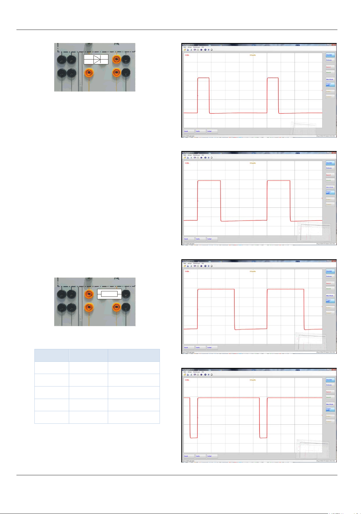
Status C «Charging» U
≈ +6.7 V, PWM active:
max
. 3 - Status C, Charging
Fig
The coding resistance for the maximum permissible charging
current can be measured betw een the PP /CC and PE mea suring
sockets. For charging cable mode 3, 3~, 739 951 that is 680 Ω,
which corresponds to 20 A.
Safety note
While charging is active, the plug is locked. Do not attempt
to forcibly pull out the plug since the locking mechanism
could otherwise be damaged!
In the delivery state, the charging request with Status D is rejected with an error message. This behaviour can be reprogrammed via the MOD BUS interface by setting th e 4010 addr ess
(16 bit) from «0» (default) to «1».
Status D «Charging» U
≈ +3.4 V, PWM active:
max
Fig. 4 - Status D, charging with ventilation
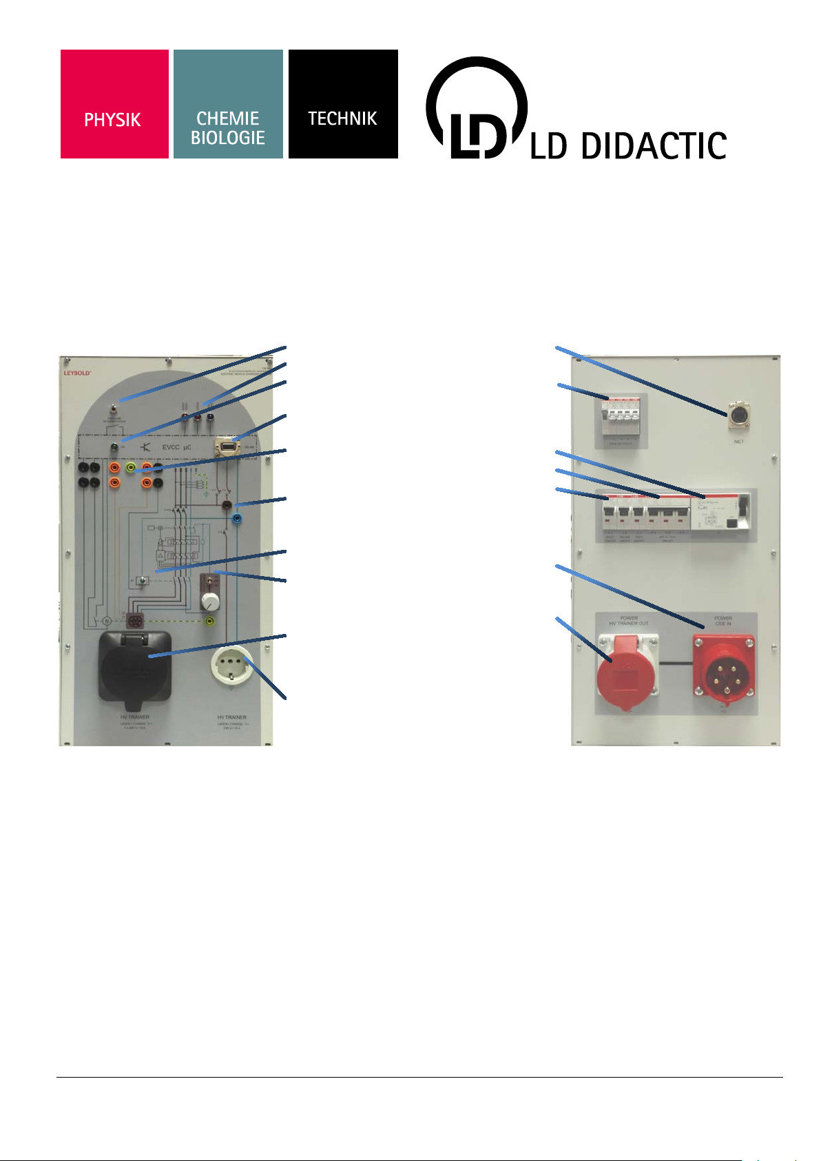
The positions of the 4 mm measuring sockets of the CP and
PP/CC signals are selected so that a plug-in element can be inserted as a replacement directly against PE.
Insert an STE diode 578 5 1 as shown in order t o gro und the v oltage of the CP signal and thus induce the «Status E» fault state.
This is indicated by an indicator light.
LEYBOLD DIDACTIC GMBH . Leyboldstrass e 1 . D-50354 Hürth, Germany . Phone +49 2233 604-0 . Fax +49 2233 604-222 . e-mail: i nfo@l eybolddidactic.de
by Leybold Didactic GmbH Printed in the Federal Republic of Germany
Technical alterations reserved
Page 4
Instructions for use 739 947 Page 4/6
Fig. 5 - Fault simulation of the CP contact
2.2 Checking the residual current circuit breaker (“RCCB”)
RC can be tripped while charging. To do this, first activate fault
#F5 and set the potentiometer t o the left stop. Subsequently use
Fig. 7 - 13 A
switch 8 to select whether you would like to induce an AC fault
current (top position)
or a DC fault current ( botto m p osition). Sin ce resi dual c urrent circuit breaker 13 must be a Type B model, residual DC currents
are detected as well.
Begin with an AC fault current (switch up). Slowly turn knob 8
clockwise to the right u ntil th e RCCB tr ips audibly. Keep the k nob
in this position! Now switch to the “DC fault current” position
(switch down) and switch the residual current circuit breaker on
again. Keep turning the knob until the DC fault current trips the
residual current circuit breaker as well.
2.3 PP resistance
. 8 - 20 A, duty cycle 33 % (33*0.6 A = 19.8 A≈20 A)
Insert an STE resis tor as s hown in order t o simulate differe nt cur-
Fig
rent carrying capacities of the charging cable as per IEC 61851.
Refer to the following table for the values.
Fig. 6 - Simulation of the current carrying capacity of the charging cable
Value [Ω]
Current [A] Item number
. 9 - 32 A, duty cycle 53 % (53*0.6 A = 31.8 A≈32 A)
Fig
100 63 577 32
220 32 577 36
680 20 577 42
1500 13 577 46
>2200 0 -
Table 1 - Coding resistances of the PP contact
. 10 - 63 A, duty cycle 89 % ([89-64]*2.5 A = 62.5 A≈63 A)
Fig
LEYBOLD DIDACTIC GMBH . Leyboldstrass e 1 . D-50354 Hürth, Germany . Phone +49 2233 604-0 . Fax +49 2233 604-222 . e-mail: i nfo@l eybolddidactic.de
by Leybold Didactic GmbH Printed in the Federal Republic of Germany
Technical alterations reserved
Page 5

Instructions for use 739 948 Page 5/6
Fault during residual current circuit brea ker
CP
PP
PE
The communication signals between the vehicle and charging
station can also be measured on the automotive high voltage
trainer, 739 947 at the intended 4 mm measuring socket for CP
against the PE socket while charging.
4 mm measuring sockets at the front of the device:
Fig. 11 - Measuring sockets on the automotive high voltage trainer, 739
Note
Even while charging, the PE socket of the charging socket is not
connected to the PE sockets of the automotive high voltage
trainer!
A “Status A” must follow after each change in resistance, otherwise the new value is not loaded!
947
3. Fault switch
Fault Description
#F1
#F2
Return information Interlock Interruption
Control Interlock Interruptio n
4.2 Establishing a connection
You need an RS485 interface (e.g. LEYBOLD
735 315USB), optiona lly a 9-pin serial standard connec tion cable as well communication software (everything not
included in the scope of deli very). You use the cable to
connect interface 4 on the charging station to the RS485
interface of the com puter. The 9-pin Sub-D socket is assigned as follows (without fixed 120 Ωterminating resistor!):
Pin 8 A
Pin 3 B
4.3 Programming
Install and start the software according to the manufacturer's specifications. An Int ernet search for «Modbus TCP
RTU Master Software» provides useful results for free software or for demo versions of programs offered commercially.
Regardless which software you are using, you will need
the following information for input:
Mode: RTU
COM port: look in the Windows Device Manager
to see the port number under which the
interface you use was set u p, her e, f or
example, number 7:
#F3
#F4
#F5
Table 2 - Meaning of the fault switches
Several faults may be activated at the same time!
PP signal Interruption
CP signal Interruption
test
4. Modbus communication
4.1 Description
You can access the device’s registers via Modbus/RTU via
system interface 4. Modbus/RTU also allows you to make
additional configurat ions on the dev ice, retr ieve status information and control access to the charging process. The
device works as a Modbus slave; the addres s is permanently set to 1. The baud r ate is 9600 for c omm unicat ion.
You can find a detail ed des cription of the regis ter assi gnment at the time this document was created here
.
Fig. 12 - Determining the COM port number
Baud: 9600
Data bits: 8
Stop bits: 1
Parity: none
Slave ID: 1
LEYBOLD DIDACTIC GMBH . Leyboldstrass e 1 . D-50354 Hürth, Germany . Phone +49 2233 604-0 . Fax +49 2233 604-222 . e-mail: i nfo@l eybolddidactic.de
by Leybold Didactic GmbH Printed in the Federal Republic of Germany
Technical alterations reserved
Page 6

Instructions for use 739 947 Page 6/6
5. Monitoring software
Follow the steps to establish a connection as described under
4.2. You can download at the time this document was cre-
the «EV CC Device Monitor» program from PHŒNIX
ated
CONTACT in order to display various information directly and
make changes. Caution: improper handling can put the de-
vice in a state that no longer permits a factory reset!
Start the program, agree to the licence then enter the interface
parameters and click the button «Connect». Available parameters will be shown automatically, changing parameters is simply
made by entering and confirming the new value.
Fig. 13 - Entering the interface parameters
If you want to read out «hardw are revisio n», for exam ple,
you will find a refer ence in the manufactur er information
that the hardware revision number is located in register
1030. The terms «address» and «register» are sometimes
used interchangeably.
In the program you also enter:
o
Address: 1030 (no offset or offset=0)
Value/data type: 16 bit (if necessary)
Function: 0x03 (read access)
Now start the requirement diagram with a «SEND» command or
similar
Fig. 14 - Reading out a register value
As a result, the charging controller returns the revision number
that is displayed in the software (in the example here, «5»
).
Use this procedure to s et register «4010» to «1», for example, in order to allow vehicles with charging status «D»
(ventilation required) without error messages (see point
2.1).
6 Maintenance
The device does not require special maintenance. Only the test
button of residual current circuit breaker 13 must be pressed
every month.
7 Technical data
• Power supply: 3x400 VAC, 50 Hz, 16 A
• Connection CEE socket 400 V/16 A, 6h
• Output voltage: 3x400 VAC, 50 Hz, 2 A
• Connection CEE plug 400 V/16 A, 6h
• Charging socket: Type 2, 16 A
• Weight: approx. 25 kg
• Protection class 1
8 Disposal
Do not dispose of electric and electronic products
with normal household waste. Dispose of the unusable product in accordance with the applicable
statutory requirements.
LEYBOLD DIDACTIC GMBH . Leyboldstrass e 1 . D-50354 Hürth, Germany . Phone +49 2233 604-0 . Fax +49 2233 604-222 . e-mail: i nfo@l eybolddidactic.de
by Leybold Didactic GmbH Printed in the Federal Republic of Germany
Technical alterations reserved
 Loading...