

Page 1
200709
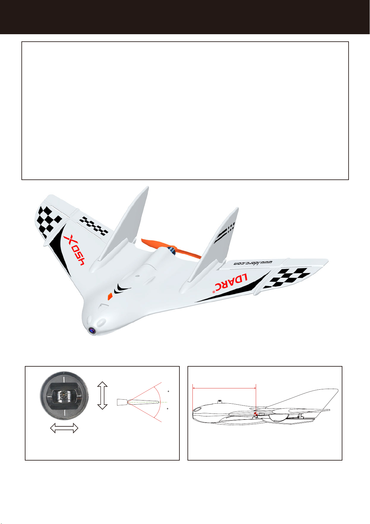
LDARC 450X V2
Configuration : □ PNP □ FPV □ RTF
User manual and video please visit:WWW.LDARC.COM
Departments 》 FPV FLY Wing 》 LDARC 450X V2
Wingspan : 431mm
Length : 277mm
Material : EPP
Prop : 3.8*3E
Battery : 7.4V 450mAh
Voltage : Only 2S
FC : FC01
ESC : 6A BLheli
Servo : WK-P0025(2.5g)*2
Motor : XT1105*5000KV
VTX : 200mW 48CH(FPV version)
Camera : RunCam micro swift 3(FPV version)
Transmitter : LDARC X6(RTF version)
Wing weight(no receiver & battery) :
PNP : 70g
FPV : 91g
RTF : 70g
Package weight :
PNP: 600g
FPV : 610g
RTF : 1150g
Package size :
PNP : 470*290*60mm
FPV : 470*290*60mm
RTF : 470*290*150mm
Tools:Screwdriver, foam glue, art knife and other tools
112mm
30
30
Roll and Pitch Center of gravity
Operate Step: Open TX > > > >Power on airplane ESC & FC self test ARM Flying
Note: Be sure to open the transmitter first, then power on the plane; and be sure to the
transmitter has been set up fail safe
-1-
Page 2
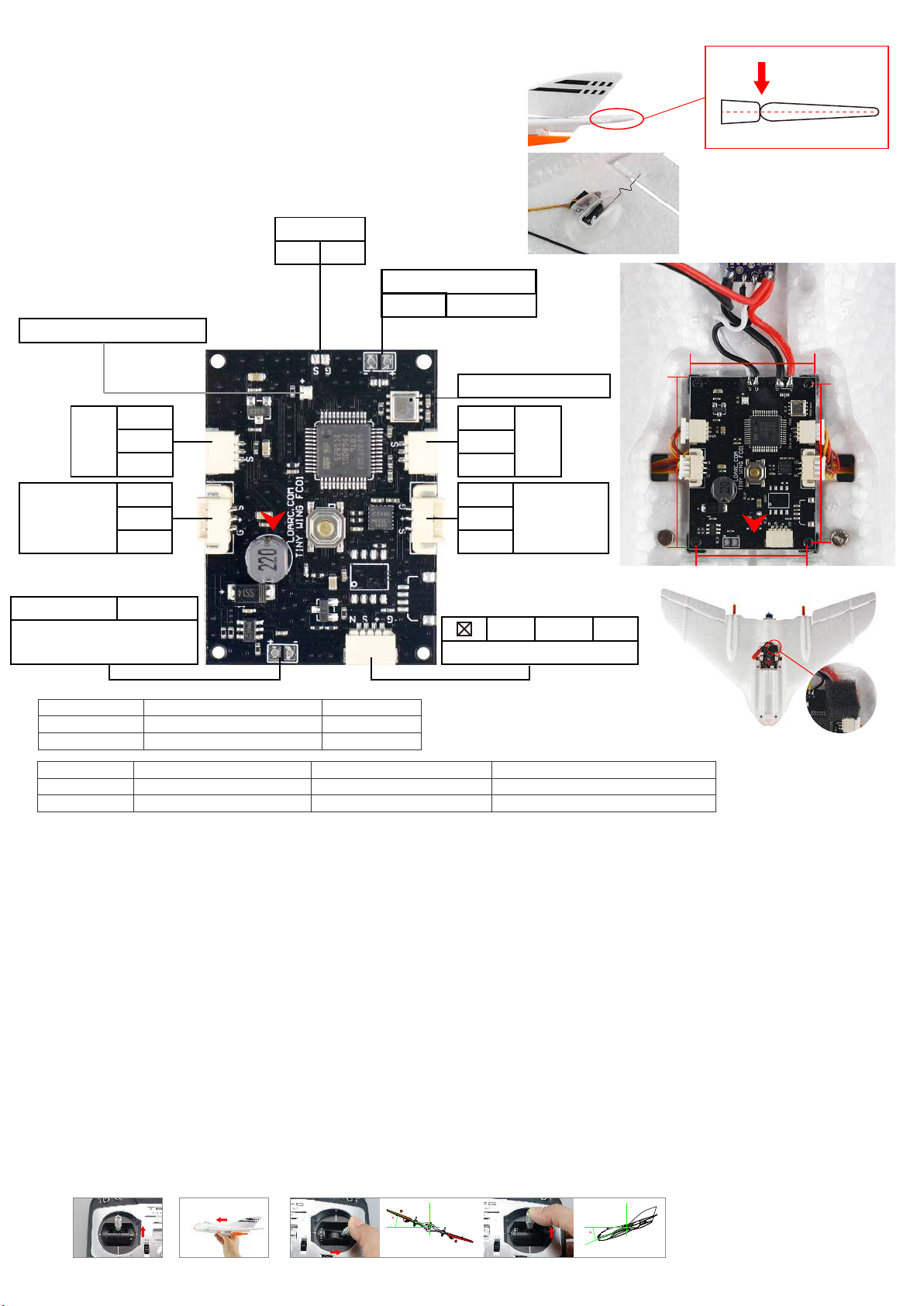
Pre-flight check:
Please switch to manual mode after the self-test
is complete on the aircraft, at which point the left
and right ailerons must be on the same horizontal
surface as the wing root; if not inconsistent, it can
be adjusted by the length of the steel rod.
FC
Mode & Self test LED
GND
LED
4.2V+
S
Servo port
1.25-3P
+
Output(Nonconnected batteries)
S
4.2V+
GND
-
ESC
S GND
2S Input(Battery)
-+
Pneumatic gauge
S
4.2V+
GND
GND
4.2V+
Servo port
1.25-3P
S
S.bus 4.2V+ GND
30mm
41mm
LED
37mm
26mm
Receiver
DIS-ARM/ARM
CH5
LED
FLIGHT MODE SELF LEVEL altitude hold on MIX LEVEL altitude hold on
CH6
LED
Fail safe:According to the TX and RX instructions setting fail safe, be sure that the motor stops when fail of TX.
Receiver:Use the S.BUS receiver,setting up fail salf and be sure that there is enough transmitter distance
ESC self test:Turn on the TX that is already bind,be sure 5CH is DIS-ARM,power on airplane and keep the airplane not moving,
about 5S later,heared a long & short alarm sound means ESC finished self test
Aircraft self-test:
Turn on the transmitter,which is already bind,and power on the plane,red LED fast flashing change
to red bright,finish self test.
Note:Be sure to complete the plane's self-test before you fly, otherwise it is easy to crash.
ARM mode: CH5(Dis-ARM, the LED always red; when ARM in self level mode, the LED always green; when ARM in mix level
mode, the LED is green flashing; when ARM in manual mode, the LED always blue.
Flight mode:
1.Self level
A:LED always green.
B:Auto throw fly, according to the wind speed, push the throttle 70%~100%(pic1).
C:Motor rotates, holding the plane horizontally thrown(pic2).
D:Keep the set high flight when the plane climbs to a height of 20 meters, now finished auto throw fly.
E:In the process of climbing, operate ailerons or lift, auto throw fly finished.
F:Self level mode,control aircraft maximum tilt angle 40 degrees(pic3).
Note:Self level mode is not suitable for intense flight, if the speed changes too fast,the rod correction will
be too high and the airplane sill shaking.
Pic1 Pic2
ARM
1700-2200
depends on(FLIGHT MODE)
1700-2200
GREEN keeps on
DIS-ARM
800-1699
RED keeps on
1300-1699
GREEN flashing
Pic3
MANUAL MODE altitude shut down
800-1299
BLUE keeps on
40
40
To avoid airflow effects,
stick a sponge above
the barometer.
-2-
Page 3
2.Mix level(LED is green flashing,you can flip it 360 degrees; air pressure set high, current height hold)
3.Manual(LED is blue light,handfree operation,FC without any intervention)
Transmitter setting:
1.Create a new standard fixed-wing model(AIRPLANE),wing type(1AIL),tail type(NORMAL).
2.Channel sort definition: ① AIL; ② ELE; ③ THR; ④ RUD; ⑤ AUX(ARM/Dis-ARM); ⑥ MOD(Flight mode).
FC function:
1.Adjustable sensor and aircraft attitude (can be continuous switched through the flight mode channel,
the speed is not too fast, because our remote control switch is a button).
2.Adjustable neutral point and rocker stroke (triggered by a button on the FC).
Aircraft Attitude Correction:
Power up in 20 seconds, switch remote control flight mode switch 6 times 1 second by 1 second (switch
frequency not fast than 1 Hz), green LED on FC Flashing, after 6 seconds, recording the current aircraft attitude
is self-stabilizing state of posture (before correction, it is best to place the head of the plane slightly upward).
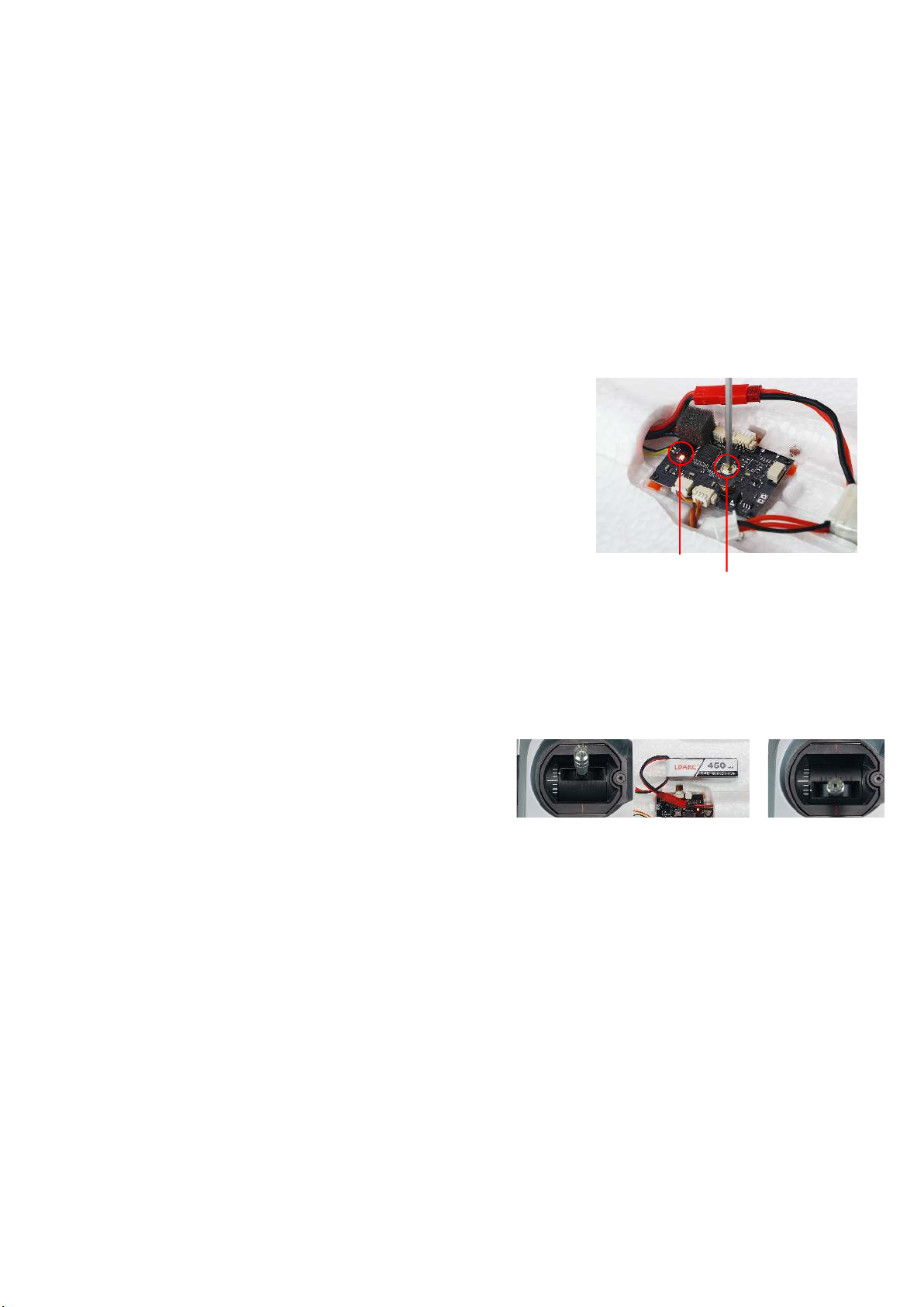
Remote Control Stroke Calibration:
Power up in 20 seconds, press and hold the FC button 3 seconds,
green LED flashing, note, green LED flashing is recording to the
neutral position of the rocker.(before calibration,Please fine-tuning
the plane well first.) note: the rocker can not move when the green
LED flashing, the blue LED flashing after 6 seconds, means enter the
remote control stroke correction, now, the rocker up and down to
the maximum position exercise once, then the LED returns to normal
instructions, the correction ends.
Note:
1.The calibration button can be only pressed effectively in 20 seconds of first power, power on more than 20
seconds, and then press invalid.
2.Neutral point before correction and correcting, rocker can not move.
3.The locking switch must be locked before it can enter the correction.
LED
Button
ESC throttle calibration:(
1.Throttle above midstick and power on,keep throttle is
above midstick for 3s(8 times Alarm)(Pic1);
2.then pull throttle is below midstick and keep 3s(2 times
Alarm), throttle calibration finished(Pic2).
Do not install propeller)
Pic1 Pic2
PNP Flight ready work:
1.Stick the EPP accessory well.
2.Calibrate aircraft posture, remote control neutral point and rocker stroke (calibration
method reference preflight preparation)
3.Install the propeller.
-3-
Page 4
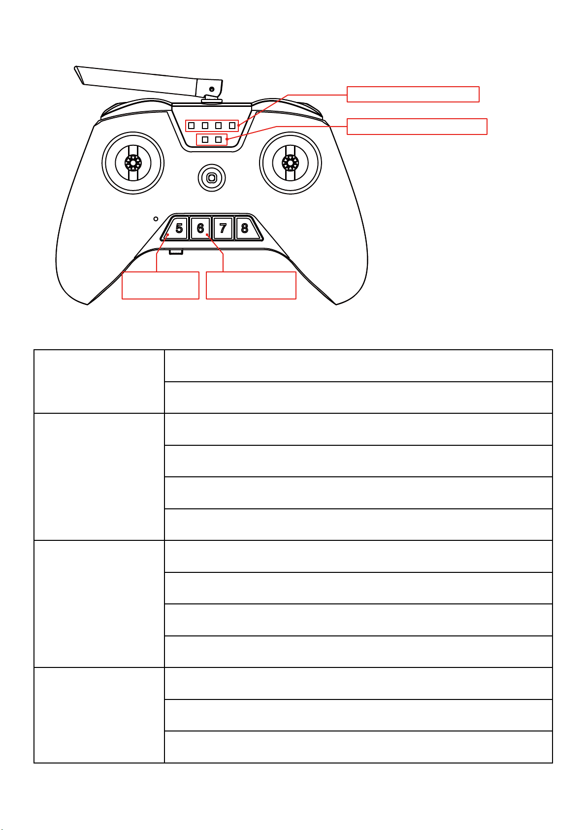
RTF version 450X radio instructions :
FLIGHT MODE INDICATOR
RADIO BATTERY INDICATOR
DIS-ARM/ARM
BUTTON
on radio
■always on
Flight mode indicator
on radio
■always on
FLIGHT MODE
SWITCH BUTTON
450X DIS-ARM, the LED on 450X wings will ■always onFlight mode indicator
Click the 【DIS-ARM/ARM BUTTON】on radio will ARM 450X
450X ARM, the LED on 450X wings will
【SELF LEVEL】, altitude hold enable
Click the 【DIS-ARM/ARM BUTTON】on radio will DIS-ARM 450X
Click the 【FLIGHT MODE SWITCH BUTTON】on radio will switch between
【SELF LEVEL】and【MIX LEVEL】
Press the 【FLIGHT MODE SWITCH BUTTON】3 seconds on radio will
switch to 【MANUAL】
450X ARM, the LED on 450X wings will
【MIX LEVEL】, altitude hold enable
■always on,fight mode
■flashing,fight mode
Flight mode indicator
on radio
■flashing slow
Flight mode indicator
on radio
■flashing fast
Click the 【DIS-ARM/ARM BUTTON】on radio will DIS-ARM 450X
Click the 【FLIGHT MODE SWITCH BUTTON】on radio will switch
between【SELF LEVEL】and【MIX LEVEL】
Press the 【FLIGHT MODE SWITCH BUTTON】3 seconds on radio will
switch to 【MANUAL】
450X ARM, the LED on 450X wings will
【MANUAL】, altitude hold disable
Click the 【DIS-ARM/ARM BUTTON】on radio will DIS-ARM 450X
Click the 【FLIGHT MODE SWITCH BUTTON】on radio will switch
to【SELF LEVEL】
■always on,fight mode
-4-
Page 5
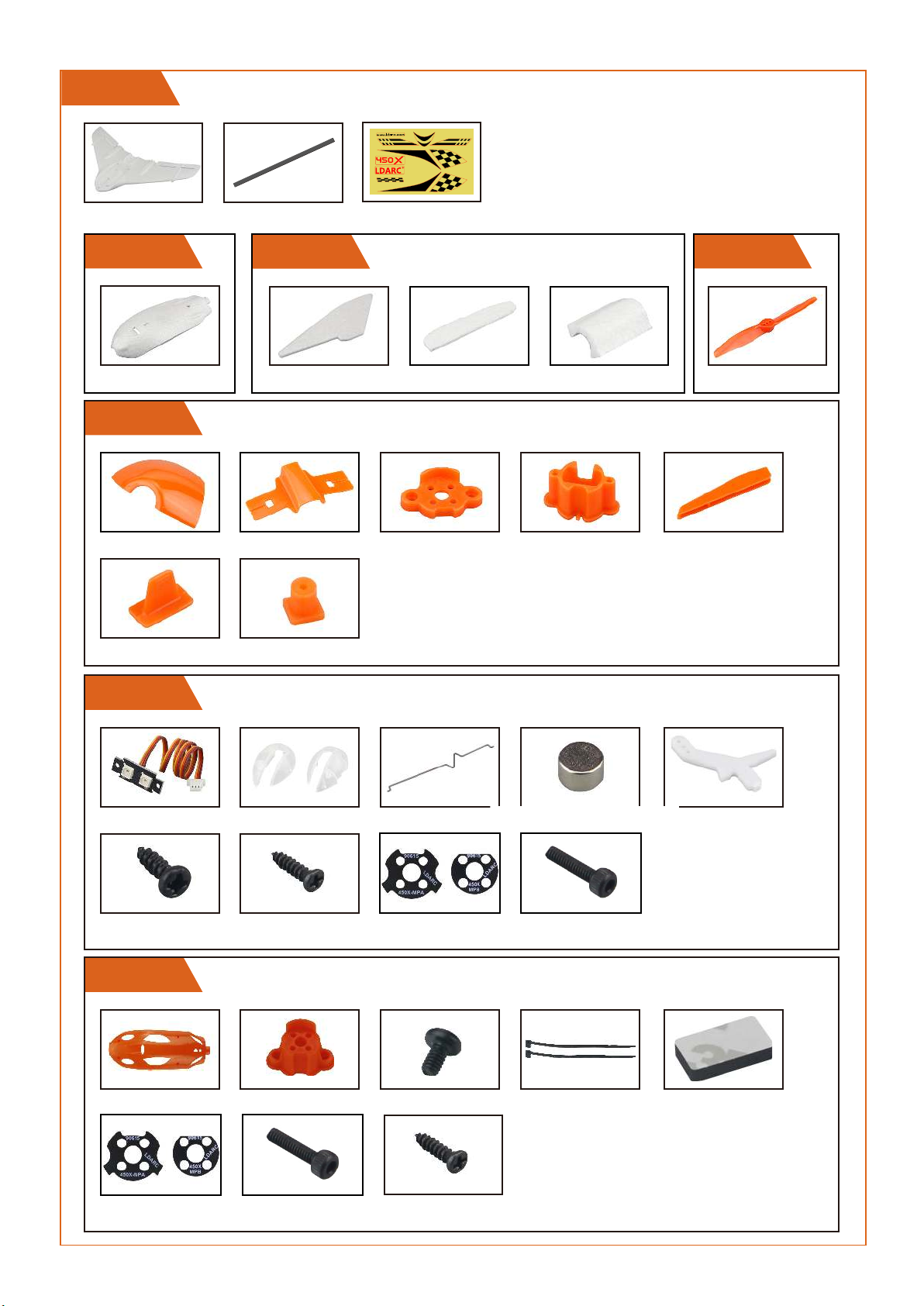
KIT Configuration Lists
KIT
Include 2PCS KIT
*2PCS *4PCS
Part 1
*2PCS
Part 4
*2PCS *2PCS
*2PCS *8PCS
Stiker*2PCS
Part 2
*4PCS *4PCS *2PCS
*2PCS *2PCS *4PCS
Orange & Black
Part 3
Prop*10PCS
orange,white,clear
Part 5
*4PCS *2pairs
ST2.0*6*4PCS ST1.5*5*16PCS
*4PCS *16PCS
Heat shields*2pairs M2*5*8PCS
Part6
*1PC *1PC *2PCS *2PCS *1PC
*4PCS
Heat shields*2pairs
M2*5*4PCS ST1.2*4*8PCS
-5-
Page 6
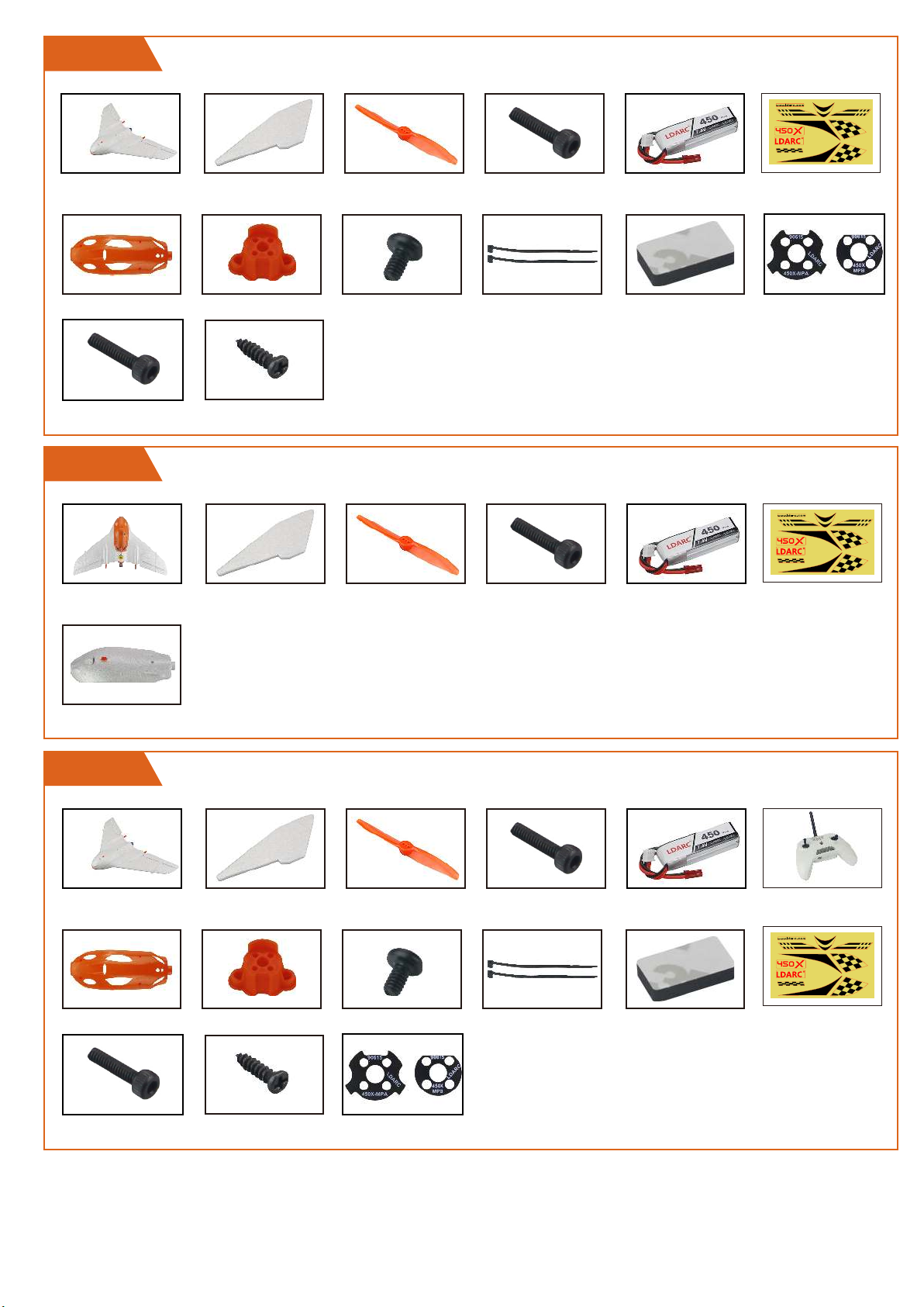
PNP
PNP*1PC *2PCS Prop*10PCS
*1PC *1PC
M2*5*4PCS ST1.2*4*8PCS
(orange,white,clear)
*2PCS *2PCS
M2*8*8PCS Battery*1PC Sticker*1PCS
FPV
FPV*1PC *2PCS M2*8*8PCS
Prop*10PCS
(orange,white,clear)
*1PC
Battery*1PC
Heat shields*2Pairs
Sticker*1PCS
*1PC
RTF
PNP*1PC *2PCS M2*8*8PCS
*1PC *1PC *2PCS *2PCS *1PC
M2*5*4PCS ST1.2*4*8PCS
Prop*10PCS
(orange,white,clear)
Heat shields*2Pairs
Battery*1PC
TX*1PC
Sticker*1PCS
-6-
Page 7
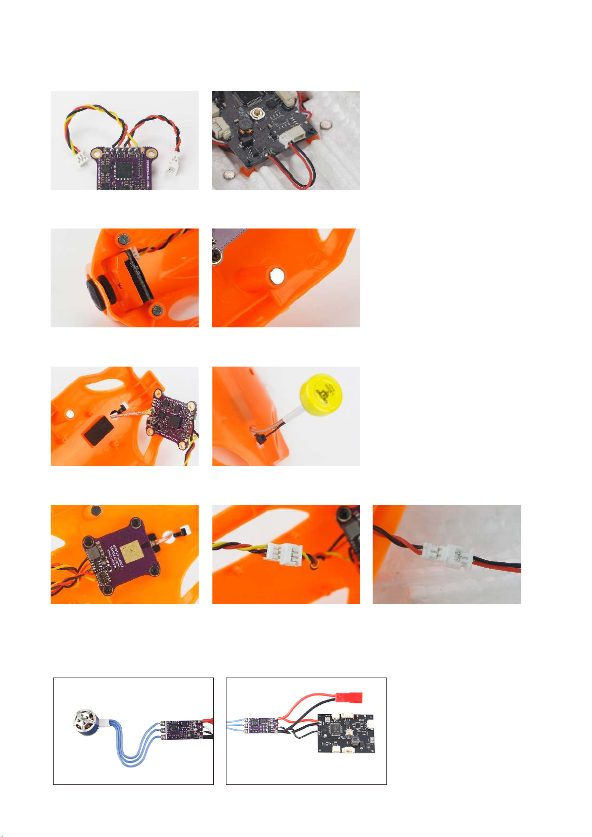
FPV install step:
1.Weld OK the FC and VTX connect wire
2.Use M2*3.5 screw install camera, and use gule stick the canopy & magnet together.
3.Connet VTX antenna,stick EVA,and fixed the antenna well.
4.Install VTX,then connect together with FC & camera.
Install steps:
1.Weld the motor, ESC, FC and power cable together , recommend that the power cable and
signal cable cut to 30mm.
-7-
Page 8
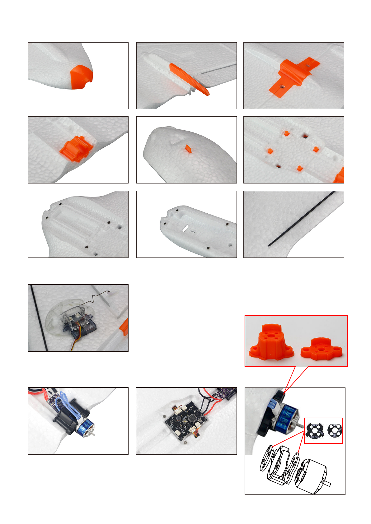
2.Use foam glue to stick EPP, plastic parts, magnets, reinforced bars well
3.Use ST1.5*5 screw install LED, servo, rudder angle, steel wire rod and lampshade.
4.Use ST1.5*5 screw install FC,ST2.0*6 screw
install motor set,then stick the EPP well.
A B
Note:When installing the motor, the motor mount seat
need to installed heat shields both inside and outside;
FPV version need use A parts install motor
-8-
 Loading...