

Page 1

TINY WING 450X
User manual and video please visit:WWW.LDARC.COM
Departments 》 FPV FLY Wing 》 TINY WING 450X
Specification
Wingspan:431mm
Length:277mm
Material:EPP
Battery position size:
78*18*16mm
KIT:34.7g
PNP weight:65g(no receiver
and battery)
Configuration
Motor:XT1104-5500KV
ESC:6A BLheli
FC:FC01
Servo:2g
Prop:3.8*3E
Color:White flywing body,orange and black plastic parts
Tools:Screwdriver, foam glue, art knife and other tools
112mm
30
30
Roll and Pitch Center of gravity
-1-
Page 2

Pre-flight check:
Please switch to manual mode after the self-test
is complete on the aircraft, at which point the left
and right ailerons must be on the same horizontal
surface as the wing root; if not inconsistent, it can
be adjusted by the length of the steel rod.
FC
LED
Servo port
1.25-3P
GND
4.2V+
S
S
4.2V+
GND
+
ESC
S GND
-
2S Input(Battery)
-+
Pneumatic gauge
S
4.2V+
GND
GND
4.2V+
Servo port
1.25-3P
S
LED
Output(Non-connected
batteries)
S.bus 4.2V+ GND
To avoid airflow effects, stick a
sponge above the barometer.
Receiver
ARM mode:
CH5(Dis-ARM, the LED always red; when ARM in self level mode, the LED always green; when ARM in mix level
mode, the LED is green flashing; when ARM in manual mode, the LED always blue.
Flight mode:
1.Self level
A:LED always green.
B:Auto throw fly, according to the wind speed, push the throttle 70%~100%(pic1).
C:Motor rotates, holding the plane horizontally thrown(pic2).
D:Keep the set high flight when the plane climbs to a height of 20 meters, now finished auto throw fly.
E:In the process of climbing, operate ailerons or lift, auto throw fly finished.
F:Self level mode,control aircraft maximum tilt angle 40 degrees(pic3).
Note:Self level mode is not suitable for intense flight, if the speed changes too fast,the rod correction will
be too high and the airplane sill shaking.
Pic1 Pic2
Pic3
40
40
-2-
Page 3
2.Mix level(LED is green flashing,you can flip it 360 degrees; air pressure set high, current height hold)
3.Manual(LED is blue light,handfree operation,FC without any intervention)
Transmitter setting:
1.Create a new standard fixed-wing model(AIRPLANE),wing type(1AIL),tail type(NORMAL).
2.Channel sort definition: ① AIL; ② ELE; ③ THR; ④ RUD; ⑤ AUX(ARM/Dis-ARM); ⑥ MOD(Flight mode).
FC function:
1.Adjustable sensor and aircraft attitude (can be continuous switched through the flight mode channel,
the speed is not too fast, because our remote control switch is a button).
2.Adjustable neutral point and rocker stroke (triggered by a button on the FC).
Aircraft Attitude Correction:
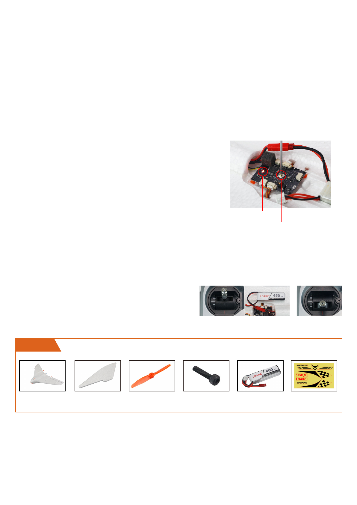
Power up in 20 seconds, switch remote control flight mode switch 6 times, FC of the green LED Flashing,
after 6 seconds, recording the current aircraft attitude is the self-stabilizing state of posture (before correction,
it is best to place the head of the plane slightly upward).
Remote Control Stroke Calibration:
Power up in 20 seconds, press and hold the FC button 3 seconds,
green LED flashing, note, green LED flashing is recording to the
neutral position of the rocker.(before calibration,Please fine-tuning
the plane well first.) note: the rocker can not move when the green
LED flashing, the blue LED flashing after 6 seconds, means enter the
remote control stroke correction, now, the rocker up and down to
the maximum position exercise once, then the LED returns to normal
instructions, the correction ends.
Note:
1.The calibration button can be only pressed effectively in 20 seconds of first power, power on more than 20
seconds, and then press invalid.
2.Neutral point before correction and correcting, rocker can not move.
3.The locking switch must be locked before it can enter the correction.
LED
Mode switch
Transmitter throttle calibration:(Do not install propeller)
1.Throttle above midstick and power on,keep throttle is
above midstick for 3s(8 times Alarm)(Pic1);
2.then pull throttle is below midstick and keep 3s(2 times
Alarm), throttle calibration finished(Pic2).
Pic1 Pic2
PNP Configuration Lists
PNP
Frame body*1PC *2PCS Prop*10PCS
(orange,white,clear)
M2*8*8PCS Battery*1PC
Stiker*2PCS
PNP Flight ready work:
1.Stick the EPP accessory well.
2.Calibrate aircraft posture, remote control neutral point and rocker stroke (calibration
method reference preflight preparation)
3.Install the propeller.
-3-
Page 4
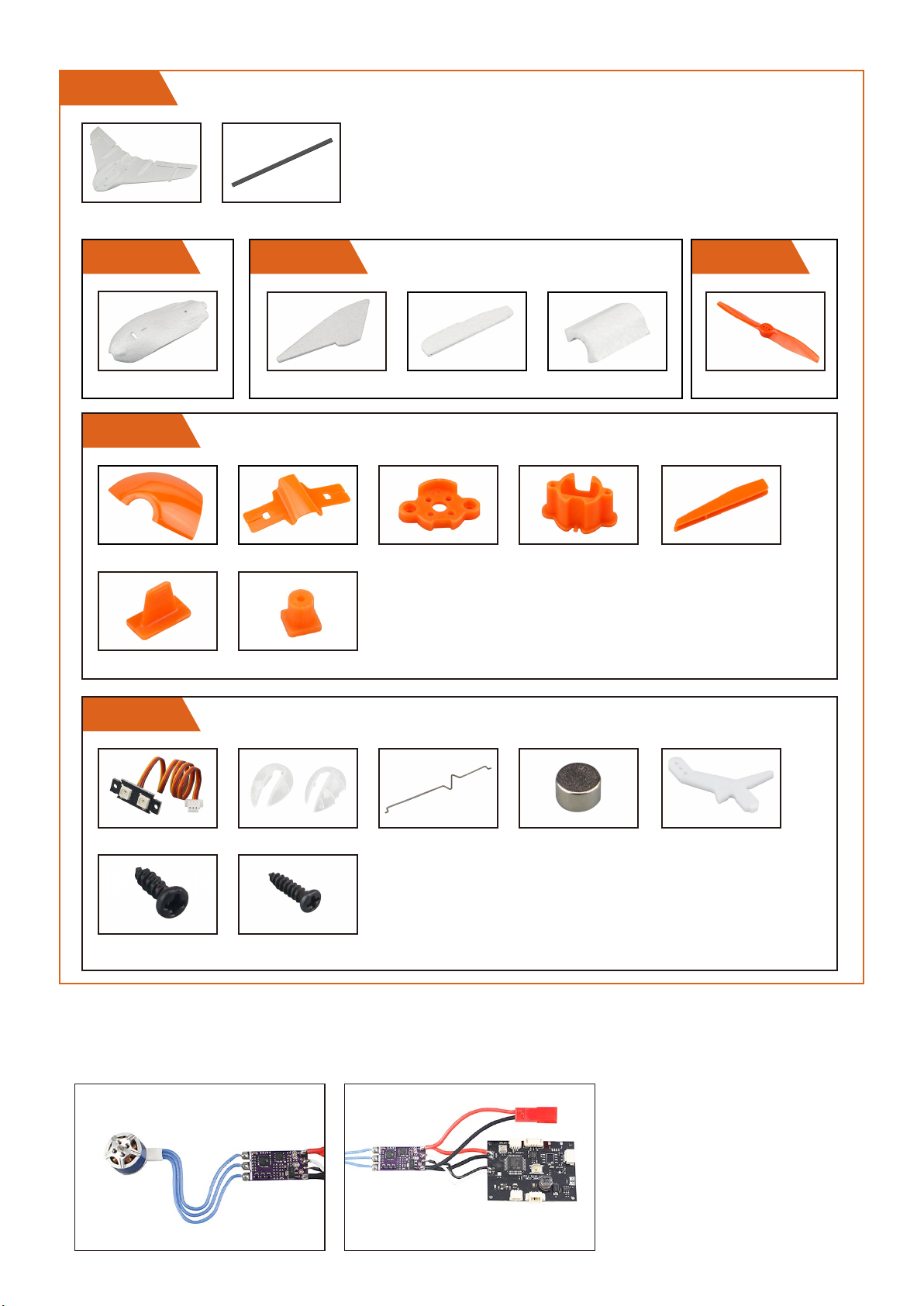
KIT Configuration Lists
KIT
*2PCS *4PCS
Include 2PCS KIT
Part 1
*2PCS
Part 4
*2PCS *2PCS
*2PCS *8PCS
Part 2
*4PCS *4PCS *2PCS
*2PCS *2PCS *4PCS
Orange & Black
Part 3
Prop*10PCS
orange,white,clear
Part 5
*4PCS *2pairs
ST2.0*6*4PCS ST1.5*5*16PCS
*4PCS *16PCS
*4PCS
Install steps:
1.Weld the motor, ESC, FC and power cable together , recommend that the power cable and
signal cable cut to 30mm.
-4-
Page 5
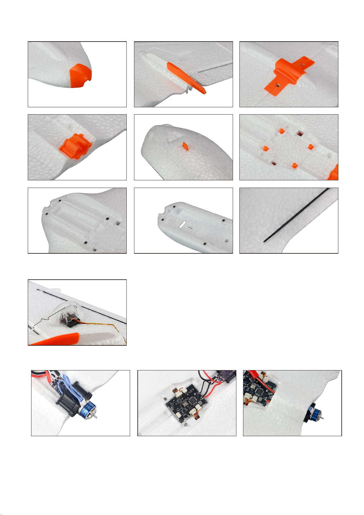
2.Use foam glue to stick EPP, plastic parts, magnets, reinforced bars well
3.Use ST1.5*5 screw install LED, servo, rudder angle, steel wire rod and lampshade.
4.Use ST1.5*5 screw install FC,ST2.0*6 screw install motor set,moter ,then stick the EPP well.
-5-
 Loading...