

Page 1

181205
ET
MAX
User manual and video please visit:
WWW.LDARC.COM
Instruction manual
Page 2

ET MAX Configuration
Pack List
-1-
Wheelbase:185mm
KK Tower:
F4+OSD
4in1 20A BLheliS
OFF/25/100/200mW 48CH
Camera:(1200TVL 1/3’COMS NTSC)
Motor:MB2204-2250KV
Prop:4*4.5*3
Weight:283g(not include battery and receiver)
PNP×1
4*4.5*3×10 Pairs
Magic tape*1
Plastic tie*5
Paper sticker*1 Card*1
Frequency Table
CH1 CH2 CH3 CH4 CH5 CH6 CH7 CH8
5865 5845 5825 5805 5785 5765 5745 5725
5733 5752 5771 5790 5809 5828 5847 5866
5705 5685 5665 5645 5885 5905 5925 5945
5740
5362
5658
5760
5400
5695
5780
5436
5732
5800
5473
5769
5820
5510
5806
5840
5547
5843
5860
5584
5880
5880
5620
5917
Band A
Band B
Band E
Band F
Band H
Band R
说明书
产品说明书请登陆 : WWW.LDARC.COM
ET MAX
产品分类
多旋翼
ET系列
ET MAX
CH1 CH2 CH3 CH4 CH5 CH6 CH7 CH8
5865 5845 5825 5805 5785 5765 5745 5725
5733 5752 5771 5790 5809 5828 5847 5866
5705 5685 5665 5645 5885 5905 5925 5945
5740
5362
5658
5760
5400
5695
5780
5436
5732
5800
5473
5769
5820
5510
5806
5840
5547
5843
5860
5584
5880
5880
5620
5917
Band A
Band B
Band E
Band F
Band H
Band R
190225
Page 3

KK Tower
+ -
Power 2~4S
M1
M2
M3
M4
-2-
LED
A V 5V
GND B+ B-
BAT
CH
BD
PW
Frequency button Frequency button
Connect FC
Frequency button
Antenna plug(I-PEX)
Receiver
3V3 RC IN GND5V+
VIDEO
VTX
Connect these 3
pads to VTX when
use 2L tower(FC+ESC)
GND5V+
3V3 RC IN GND
RC IN GND5V+
DSMX
S.BUS/PPM
LED+Buzzer
5V(BUZZER+) LED(S) GNDBUZZER-
Camera
5V+ GND VIDEO
AUDIO
USB
BOOT
USB
Bule LED is channel (CH) indicator,flash 1~8 times mean CH-1~8.Green LED is band(BD) indicator,flash 1~6 times mean
BAND-A~F,Red is output power(PW)indicator,flash 1~3 times mean 25mW/100mW/200mW output power.In normal
working state,quickly double-click button,R/G/B sync flash mean VTX turned off,and also quickly double-click can turn
on the VTX.in normal working state,press and hold the key for 3s,only blue led flashes,now click the key change
channel(CH).press and hold the key for 3s,only blue green flashes,now click the key change band(BD) .press and hold
the key for 3s,only red led flashes,now click the key change output power(PW).
Page 4

BIND:Power on the receiver while pressing the key,green LED fast blink meaning already in bind mode,user can release the key,
then set your TX into bind mode.Green LED turn off and red LED solid mean bind finished,exit TX from bind mode,receiver’s
green LED solid mean working normally.
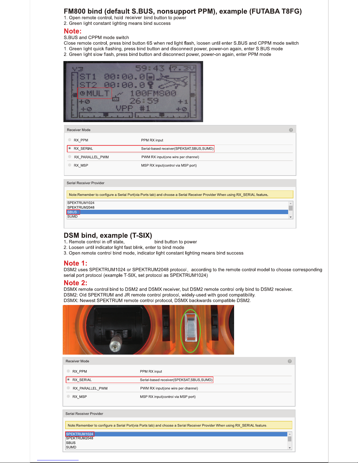
Receiver Bind
AC900(S-FHSS+D16 non-EU) bind,transmitter(FRSKY X9D/Futaba T18SZ)
RX2A PRO Bind(S.BUS),transmitter(FLYSKY FS-i6)
-3-
Bind:Check receiver mode before bind,the first blink after power on indicate the setting, is S-FHSS, is D16(non-EU)
FUTABA S-FHSS BIND:Turn on the TX then power on AC900 while pressing the key, green LED fast blink meaning already in bind
mode, user can release the key. Bind procedure is completed and the receiver is working normally when green LED is solid
FRSKY D16(NO Telemetry) BIND:Power on AC900 while pressing the key, green LED fast blink meaning already in bind mode,
user can release the key, then set your TX into D16 bind mode. red LED solid meaning bind finished, exit TX from bind mode,
receiver’s green LED solid meaning working normally
Page 5
-4-
Page 6
-5-
Product and Factory Code
Name
ET MAX PNP
ET MAX KIT
ET MAX Canopy
C1200 Camera
MB2204-2250KV(CW)
MB2204-2250KV(CCW)
KK Tower(3 Layer) 20A
4in1 ESC 20A(KK Tower part)
F4+OSD(KK Tower part)
VTX(KK Tower part)
Wire(KK Tower part)
3 Layer Tower Screw(KK Tower part)
4*4.5*3 Prop(clear black)
4 Inch propeller bumper
Carbon plate(ET MAX part)
LED+Buzzer(ET V2/3S part)
Factory Code
PNP.ET MAX
KIT.ET MAX
PART.ET MAX CANOPY
CAM.C1200
MOTOR.MB2204-2250KV(CW)
MOTOR.MB2204-2250KV(CCW)
FLYTOWER.KK TOWER(3 LAYER) 20A
ESC.KK TOWER 20A
FC.KK TOWER(F4+OSD)
VTX.KK TOWER
PART.KK TOWER WIRE
PART.KK TOWER SCREW(3 LAYER)
PROP.4*4.5*3
PART.4 INCH PROPELLER BUMPER
PART. BOTTOM PLATE.ET MAX
PART.LED+BUZZER(ET V2/3S PART)
Factory setting
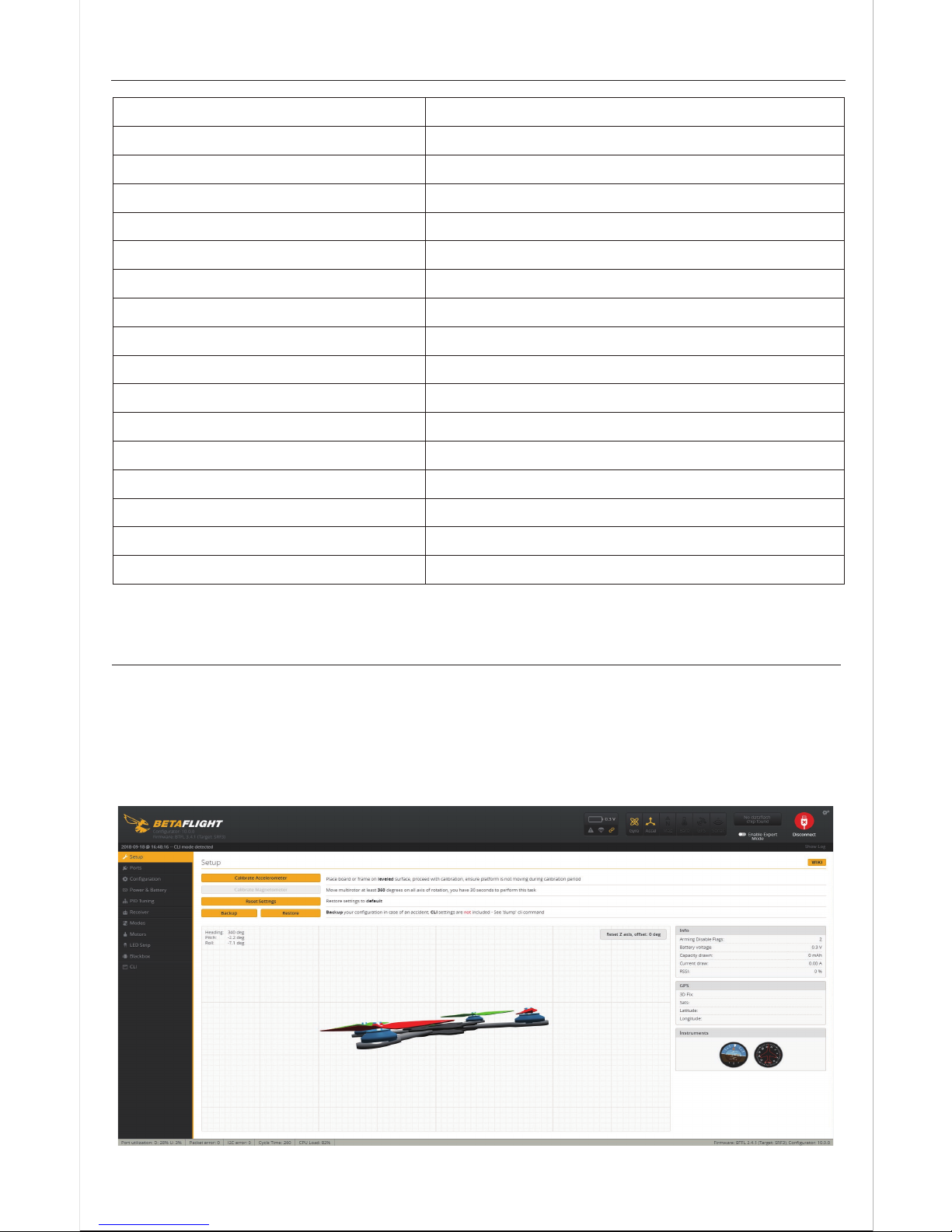
The factory has already load the firmware, default angle mode, please set
directly
2.Click“Calibrate Accelerometer”
1.Open Betaflight
Page 7
-6-
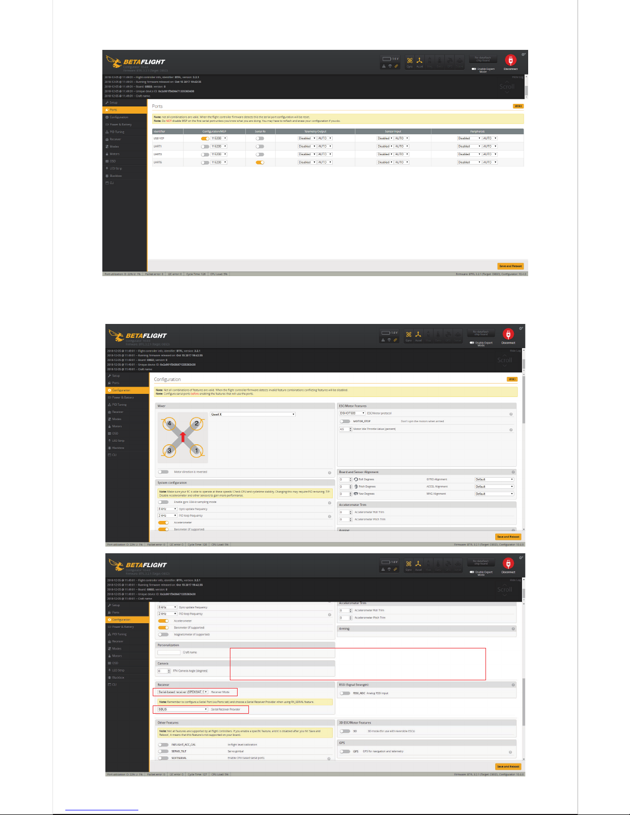
3.Prot,open UART6 switchable and saved
4.Select ESC protocol“DSHOT600”,set up the receiver protocol,
open LED_STRIP,OSD,DYNAMIC_,FILTER
Please refer to the receiver section
to set the receiver protocol
Page 8
-7-
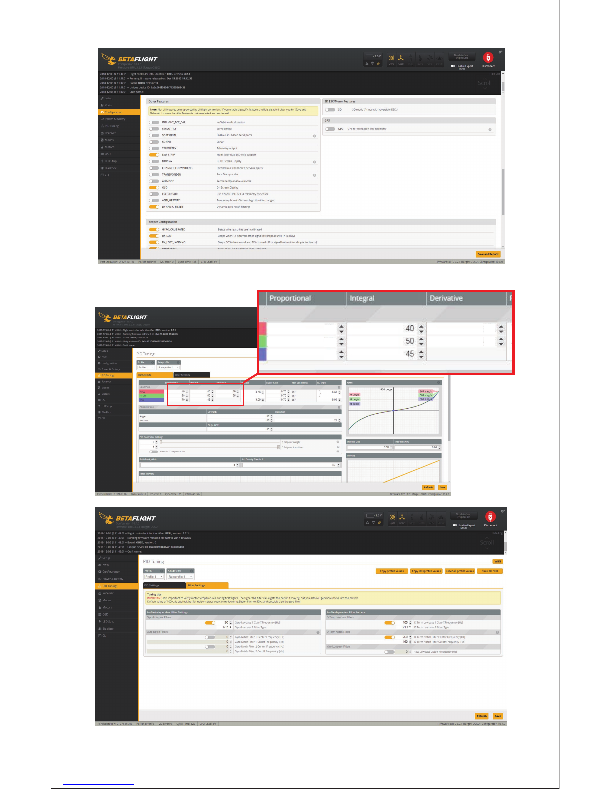
5.PID setting
40
58
70
30
35
Page 9
-8-
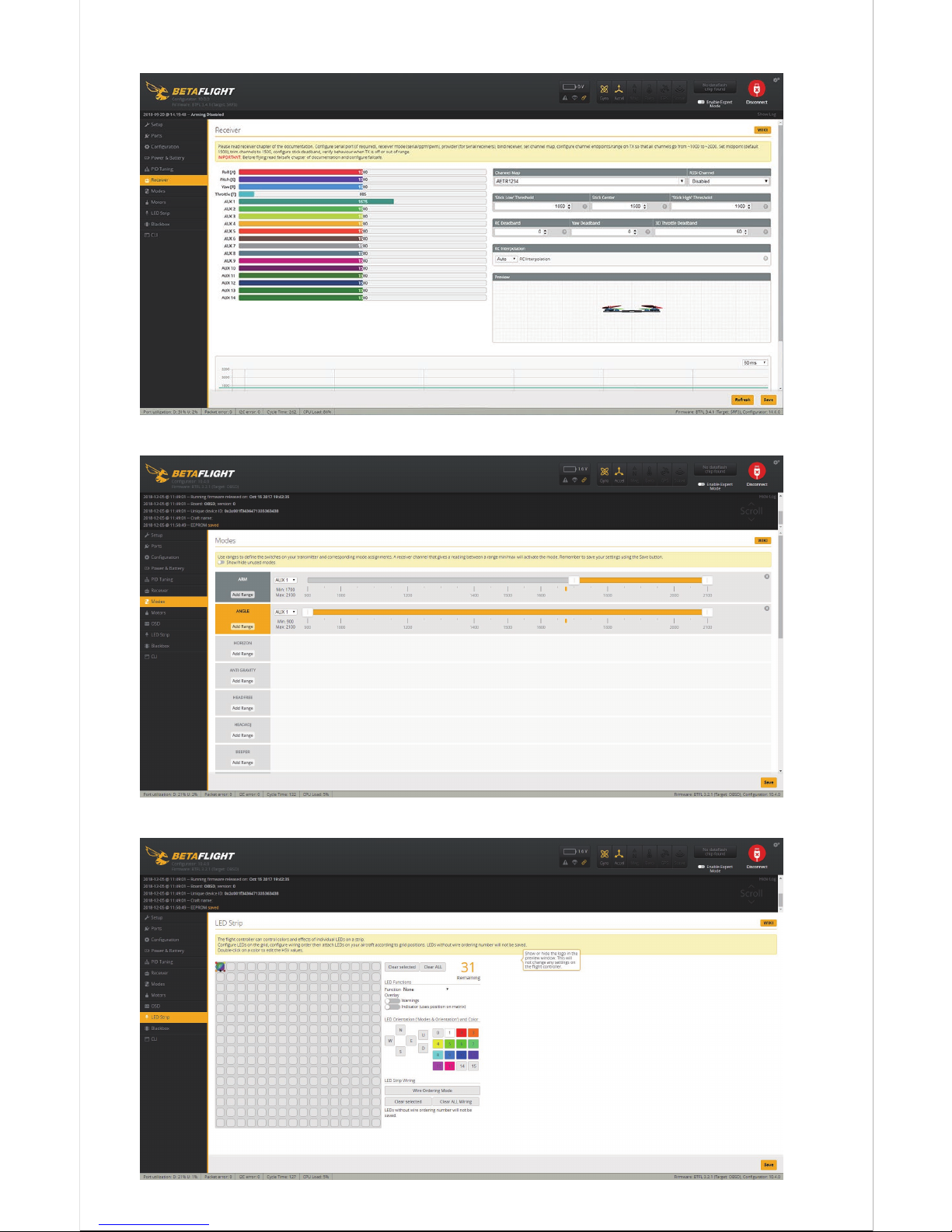
7.Default angle mode,setting of receiver is 5th channel ARM(AUX1)
8.LED setting,then saved
6.Setting the receiver lever neutral position
Page 10
-9-
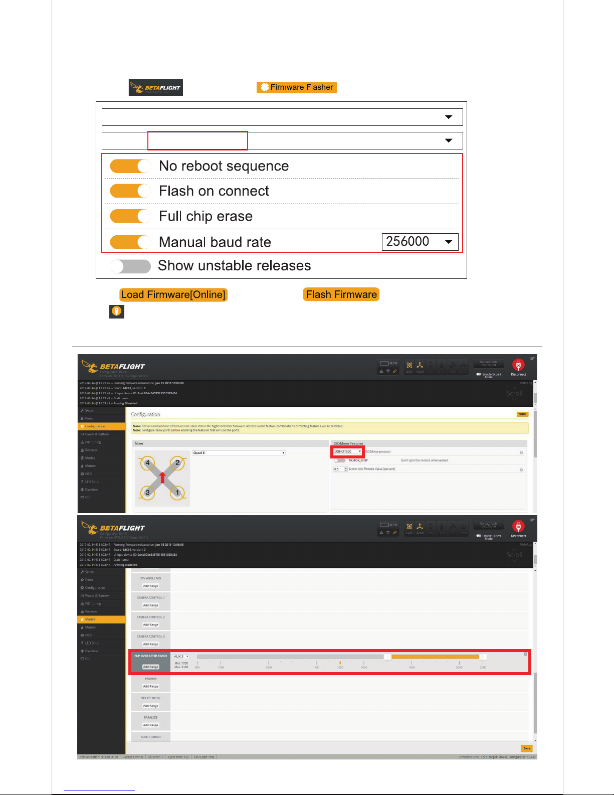
1.Open ,then click ,select firmware
OMNIBUSF4SD
3.2.1- OMNIBUSF4SD -18-10-2017 03:31(stable)
When the drone is not flying properly, try to load FC firmware,then restore
factory settings
2.Click ,then click to download FW to FC,
click after FW updating finish into setting menu
Connect
Flip Over After Crash Setting
Open Flip Over After Crash mode and assign switching channels
Setting ESC protocol is“DSHOT600”
Page 11

-10-
After Sale Service
1.Provide free reparation service when find the product defect after purchase.
2.Provide pay-needed reparation service when product damage because
improper operation.
3.China customers please contact with the after-sales service,overseas client
please contact the dealer.
PNP/RTF Test report ID :
Flight test
Flying in good condition
Camera OK
VTX OK
QC:
Package check
PNP
Frame
All parts of the installation
Insulating sleeves have been installed manual
Complete accessories,total packages
QC:
 Loading...