

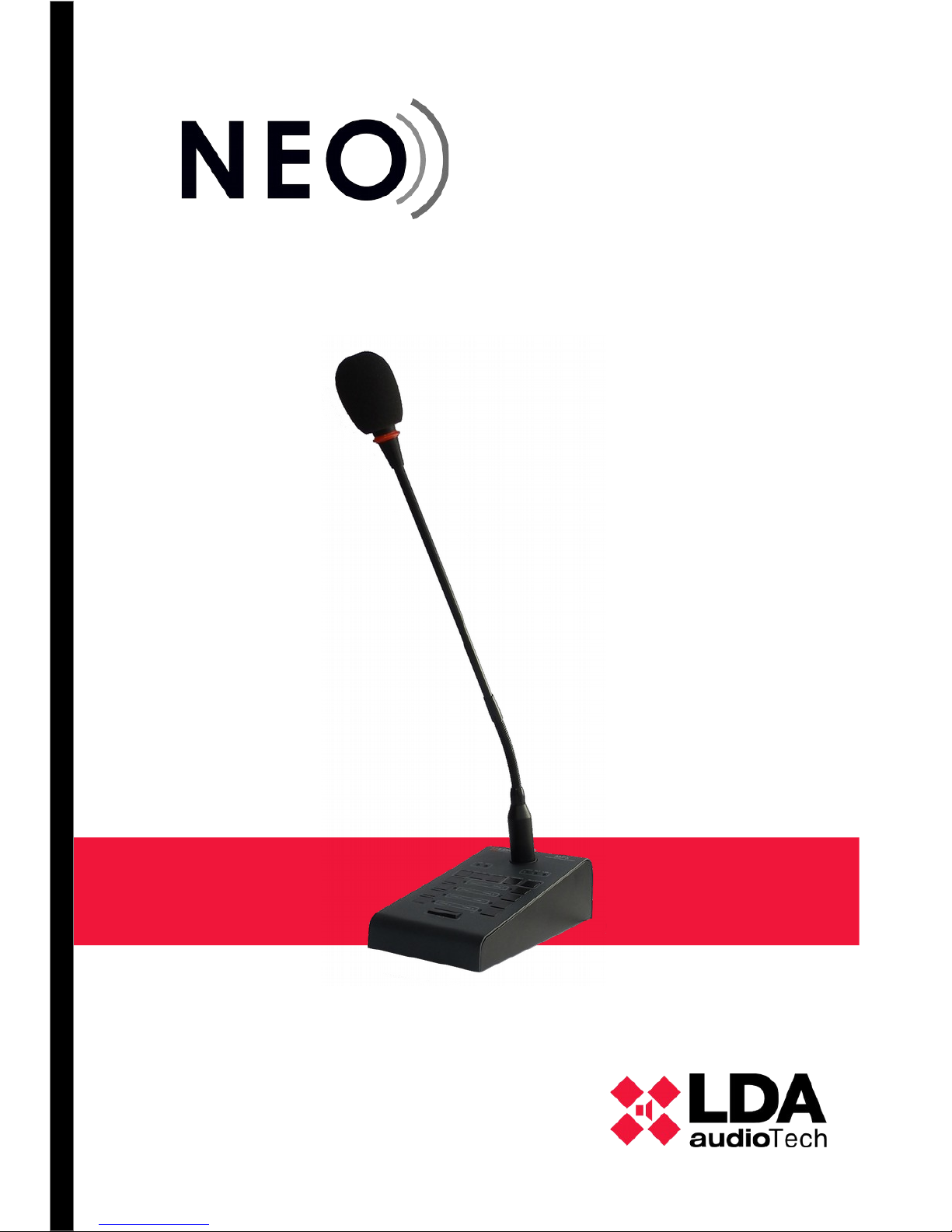
User's Manual
Model: MPS 8Z


Content
1 INTRODUCTION............................................................................................................................ 1
2 DESCRIPTION............................................................................................................................... 1
2.1 INDICATORS.......................................................................................................................................... 2
2.1.1 SYSTEM STATUS INDICATORS....................................................................................................................2
2.1.2 STATUS INDICATORS OF THE CALL CHANNEL.........................................................................................2
2.2 CONTROLS............................................................................................................................................ 3
2.2.1 ADVANCED FUNCTION CONTROLS ...........................................................................................................3
2.2.2 CALL FUNCTIONS CONTROLS.....................................................................................................................3
2.3 INPUTS AND OUTPUTS........................................................................................................................ 4
2.3.1 MIC..................................................................................................................................................................4
2.3.2 INPUT / OUTPUT FOR PUBLIC ADDRESS AND VOICE ALARM SYSTEM (“ACSI” LOOP) .......................4
2.3.3 AUXILIAR POWER SUPPLY...........................................................................................................................5
2.3.4 PORTS FOR EXPANSION KEYBOARDS.......................................................................................................5
3 OPERATION DESCRIPTION:....................................................................................................... 5
3.1 TURNING ON......................................................................................................................................... 5
3.2 KEYBOARD LOCK................................................................................................................................ 5
3.3 PAGING VOICE ANNOUNCEMENTS................................................................................................... 6
3.3.1 ZONE MEMORY SELECTION........................................................................................................................6
3.3.2 ZONE MEMORY GROUP SELECTION .........................................................................................................6
3.3.3 RECORDING ZONE MEMORY GROUP.........................................................................................................6
3.3.4 RECALL...........................................................................................................................................................6
3.4 SYSTEM EVENT.................................................................................................................................... 7
3.4.1 LAUNCHING SYSTEM EVENTS.....................................................................................................................7
4 CONNECTION AND SETTING UP................................................................................................ 7
4.1 POWER SUPPLY................................................................................................................................... 7
4.1.1 POWER SUPPLY SELECTOR........................................................................................................................7
4.2 CONNECTION TO THE SYSTEM (ACSI BUS)..................................................................................... 8
4.2.1 BUS TERMINATOR.........................................................................................................................................8
4.3 MPS-8K EXPANSION KEYBOARDS INSTALATION........................................................................... 9
4.3.1 KEYBOARD ID..............................................................................................................................................10
4.4 MPS 8Z CONFIGURATION.................................................................................................................. 10
4.4.1 CONFIGURATION. TALK..............................................................................................................................11
4.4.2 CONFIGURATION. CHIME...........................................................................................................................11
4.4.3 CONFIGURATION. EXTERNAL MICROPHONE.........................................................................................11
4.4.4 CONFIGURATION. DSA...............................................................................................................................11
4.4.5 CONFIGURATION. LOCK.............................................................................................................................11
4.4.6 CONFIGURATION. OUTPUT VOLUME .......................................................................................................11
5 UPDATE....................................................................................................................................... 12
6 FAULT RESOLUTIONS............................................................................................................... 12
6.1 THERE IS NO LINK WITH THE SYSTEM........................................................................................... 12
6.2 STATE LED INDICATORS BLINK simultaneously........................................................................... 12
6.3 NO LED INDICATOR IS ON................................................................................................................. 12
6.4 THE VOICE ANNOUNCEMENT IS VERY LOUD/LOW...................................................................... 13
6.5 IS NOT POSSIBLE TO HEAR THE VOICE ANNOUNCEMENT......................................................... 13
6.6 THE EXPANSION KEYBOARD DOES NOT ADDRESS THE SELECTED ZONES..........................13
6.7 THE EXPANSION KEYBOARD DOES NOT SWITCH ON................................................................. 14
7 MAINTENANCE INDICATIONS.................................................................................................. 14
8 TECHNICAL SPECIFICATIONS................................................................................................. 15

SECURITY INSTRUCTIONS
1. Keep this User Manual for future reference.
2. Unplug the unit from the power outlet before cleaning it.
3. Do not put containers containing liquids on the device. Do not pour liquids on the unit.
4. Install this equipment on a safe surface. If you do not place the equipment on a safe
surface, it may fall and be damaged.
5. Do not place the equipment over flame sources, such as candles.
6. Always keep in mind all warnings and precautions of the equipment.
7. Never open the equipment. For safety reasons, the equipment should only be manipulated
by qualified personnel.
8. Pay attention to the connection polarity, when operating the equipment with a direct current
(DC) power source. The reversed polarity connection can cause damage to the equipment,
or to the power supply.
9. If any of these situations arise, let the technical staff check the equipment:
a) The power cord or plug is damaged.
b) Liquid has penetrated inside the equipment.
c) The equipment has been exposed to moisture.
d) The equipment has not worked well or does not work according to the instruction
manual.
e) The equipment has dropped and been damaged.
f) If the equipment has obvious signs of damage.
10. Disconnect the audio inputs and outputs while making the connections. Be sure to use the
appropriate cables to make the connection.

1 INTRODUCTION
The series of MPS paging stations is designed to provide the system with high-quality
public address and performance microphones. The expansion keyboards available, allow it to
adjust to the particularities of each system in terms of zones.
2 DESCRIPTION
The microphone desk MPS 8Z allows to give live voice announcements messages for up
to 64 memories of selection of public address zones of a NEO system.
FUNCTIONS
1. 8 zone memories with addressing of 8 zones per memory, 64 zones
2. Up to 64 zone memories with addressing of 8 zones per memory, 512 zones (by means of
expansion keypads)
3. 8 memories for system events
4. Recall (from latest live PA message)
5. Ding dong (chime)
6. External microphone input
7. Volume adjustment
8. System evacuation status indicator
9. System failure status indicator
10. Status indicator of link with the system
11. Zone memory selection indicator
12. Word indicator granted
13. Busy line indicator
14. 8 Zone memory selection indicators
15. Keypad lock
16. Zone memory pre-selection memory
17. DSA ("Dynamic Sound Adjuster")
LDA Audio Tech – 31 Severo Ochoa - 29590 MALAGA, Spain. Tel: +34 952028805
1
User's Manual: MPS 8Z
2.1 INDICATORS
2.1.1 SYSTEM STATUS INDICATORS
The status indicators show at all times
the working condition of the equipment or
system. They are located in the upper right
corner of the equipment.
(a) EMG: “EMERGENCY”
Active (on) when the system is in emergency
operation state (voice alarm). Under this state,
the MPS 8Z may not be able to make live PA
live messages, as it has been configured in the
system (see NEO system configuration
manual). Red color.
(b) FLT: “FAULT”
Active (on) when the system is in a fault state.
This indicator is activated automatically after
the failure detection of any of the supervised
functions. Yellow color
(c) LINK: “LINK”
Active (on) when the equipment is linked to the
system. It will blink while the process of linking
to the system or there is a link failure between
the equipment and some element of the
distributed system. If the problem persists, see
chapter 6.4 for resolution. Yellow color
2.1.2 STATUS INDICATORS OF THE CALL CHANNEL
The status indicators per channel, show at all times their status or operating condition.
(d) BSY: “BUSY”
Active (on) when the call channel is occupied by another device with higher priority in the
ACSI bus. When during a voice announcement, the call channel is occupied by a device with
a higher priority, it will light up intermittently, indicating that the call has been canceled. Red
color.
(e) CW: “CONCEDED WORD”
Active (on) when the call channel is assigned and free to be able to make a PA voice
announcement. When the pre-warning tone is active on the equipment, it will flash
intermittently while it is playing. Green color.
Complementary to this indicator, the MPS 8Z includes an illuminated ring located in the
microphone capsule that shows when the user can begin to make the voice message. Red
color.
(f) ZONE x: “ZONE x”
Active (on) when the memory or zone memories X have been selected. Green color
2
www.lda-audiotech.com
Picture 1: Indicators

2.2 CONTROLS
2.2.1 ADVANCED FUNCTION CONTROLS
(a) “MEM”
The "MEM" button is located to the left of the
upper area of the keyboard. It allows access to the
configured zone memory preselections.
(b) “EVENT”
The "EVENTS" button is located in second
position from the left side in the upper area of the
keyboard. Allows access to the selection of system
events.
(c) “CANCEL”
The "CANCEL" button is located in the middle
of the upper area of the keyboard. It allows canceling
those operations that require confirmation. It also
serves as an access key to the configuration
functions of the equipment.
(d) “RECALL”
The "RECALL" button is located in the second
position from the right side in the upper area of the
keyboard. It allows to repeat the last voice
announcement message into the selected zone
memories.
(e) “ALL / CLEAR”
The "ALL / CLEAR" button is located to the
right of the upper area of the keyboard. Allows the
selection of all available zone memories. When one
or more zone memories are selected, by pressing
this button it will unselect all.
2.2.2 CALL FUNCTIONS CONTROLS
(f) ZONE MEMORY
They are located in the lower half of the microphone desk. They allow the selection of
zone memories, and the voice message, one or several simultaneously. When a memory is
selected, the memory indicator will be activated.
(g) “TALK”
It is located at the bottom of the keyboard, occupying the central area. It allows to request
the channel to make the voice announcement call through the selected zone memories. It also
acts as confirmation "OK" of the operations that require it.
LDA Audio Tech – 31 Severo Ochoa - 29590 MALAGA, Spain. Tel: +34 952028805
3
User's Manual: MPS 8Z
Picture 2: Controls

2.3 INPUTS AND OUTPUTS
2.3.1 MIC
It allows the connection of an external dynamic microphone. More precisely, this input is a
3.5mm (1/4 ") mini-jack input.
This input has three terminals for the connection of an unbalanced mono input signal, where one
of the terminals has no connection.
The connection is made through a male mini-jack type connector with 3 contacts of 1/4 ".
Mark Description Type Signs Activation
1 Audio signal unbalanced Input
+
Configuration (see 4.4.3)
2 No connected NC
3 GND Input
┴
Table 1: Input External microphone
2.3.2 INPUT / OUTPUT FOR PUBLIC ADDRESS AND VOICE ALARM SYSTEM (“ACSI” LOOP)
The equipment has two connections for distributed elements in Public Address systems. It
consists of a line level audio input plus control signals for connecting up to 8 devices in 'daisy
chain' bus, where each device is connected to the next. Both connections are identical and
interconnected. The ACSI bus supplies remote power to the equipment, see chapter 4
The connection is done through a standard Ethernet T568B cable. Maximum connection
distance for all the bus is 1000m (3280ft).
Mark Description Type Signals Activation
ACSI
BUS
Line level balanced audio.
Control and power bus.
Input Protocol N/A
Table 2:Bus ACSI connection
NOTE: This connection is not compatible with standard ethernet.
4
www.lda-audiotech.com
Picture 3: Inputs and Outputs

2.3.3 AUXILIAR POWER SUPPLY
The equipment has an auxiliary power supply. Emergency voltage is continue and has a
nominal value of 5V. It will be externally supplied through an USB charger, included with the
equipment (female miniUSB connector).
Mark Description Type Signals Activation
POWER
USB
Auxiliar power supply input. Port USB 1.1
5V DC
Max Current: see technicals
characteristics (chapter 8 )
Table 3: Auxiliar power supply input
Connection is done through a male miniUSB cable, AB type (supplied with the system)
2.3.4 PORTS FOR EXPANSION KEYBOARDS
The equipment has two available ports for connecting additional keyboards, one on each
side of the unit. Only one of the ports can be used simultaneously.
Mark Description Type Signals Activation
-
Expansion port I/O
-
N/A
Table 4: Expansion port
3 OPERATION DESCRIPTION:
3.1 TURNING ON
Select the power supply origin as shown on 4.1. Connect the power supply cable into
'POWER' connector located on the back side of the equipment, or directly through the ACSI bus.
On the frontal side of the equipment, a check indicators sequence will start. Once the sequence is
finished, linking with system process will start and it will be shown in the corresponding indicator.
When you turn on the equipment for the first time, you must make the typical installation
adjustments (see chapter 4)
3.2 KEYBOARD LOCK
The MPS 8Z has an optional feature to lock the keyboard. To configure key lock, please
see section 4.4.5.
If any button is pushed during the key lock, the zone memory indicators will blink four times.
LDA Audio Tech – 31 Severo Ochoa - 29590 MALAGA, Spain. Tel: +34 952028805
5
User's Manual: MPS 8Z

When this feature is activated, keyboard locks manually or automatically after 60 seconds
from the last operation. To lock the keyboard, press the “CANCEL” and “TALK” keys
simultaneously. The zone memory indicators will blink once. To unlock the keyboard, press again
“CANCEL” and “TALK” keys. he zone memory indicators will blink twice.
3.3 PAGING VOICE ANNOUNCEMENTS
To page a voice announcement, select the zone memories which you want to issue the
warning. Their selection indicators will light up. Then push “TALK” key. If the notice channel is
available, the “CW” indicator will light up and the equipment will be ready to issue the warning. If
the prior notice tone is set, the “CW” indicator will light up intermittently until it is completed. If the
channel is not available, the “BSY” indicator will light up.
3.3.1 ZONE MEMORY SELECTION
To issue a warning, you can click every selection control of the zone memories or use the
“ALL/CLR” key. This control will select every single zone. If you want to deselect them, press the
desired zone control again or the “ALL/CLR” key if you want to do it with all of them. Zone
memory indicators will turn off.
By default, the system zones which are assigned to each MPS 8Z coincide with the zones of the
system. That way in the memory of Zone 1 we can select Zone 1 and in the memory 2 the zone 2.
The zones assigned to each zone memory can contain up to 8 zones of the system. Thus one
MPS 8Z can address up to 64 zones of the system, and up to 512 zones if it is equipped with
expansion keyboards.
3.3.2 ZONE MEMORY GROUP SELECTION
The equipment allows to record zone memory shortlists for user's comfort. To select a
group, push the “MEM” control and then one of the set groups assigned to one of the selection
zone controls. The group of zone memories will remain selected and their selection indicators will
light up.
3.3.3 RECORDING ZONE MEMORY GROUP
The equipment allows to record zone memory shortlists for user's comfort. To make the
recording follow the next procedure:
• Ensure that the equipment has not conceded word. The “CW” indicator will be off.
• Press the zone memories you want to be part of the group.
• Hold the “MEMORY” key for a second.
• Selection leds blinks.
• Press the zone memory where you want to assign the group.
3.3.4 RECALL
The system has a memory to record up to 45 seconds of the last voice message. To
repeat the message issued, select the zones you want to issue the message in, then press
“RECALL”. “CW” indicator will start blinking. Confirm by pressing the “TALK” button before 3
seconds. If the notice channel is available, the “CW” indicator will light up, otherwise the “BSY”
indicator will light up.
To cancel the recall, press “CANCEL” button. “CW” indicator will turn off.
6
www.lda-audiotech.com

NOTE: If different messages are issued before 15 seconds, the recording may not be
done to protect the memory. In this case when you press “RECALL” key, “BSY” indicator will
automatically light up showing there is no recorded message.
3.4 SYSTEM EVENT
The desktop microphone MPS 8Z allows to launch system events, such as pre-recorded
messages issuance, sound sources assignment, zone volume control, etc. To assign system
events to zone memory selection buttons of the MPS 8Z, see the software configuration User's
Manual of NEO system.
3.4.1 LAUNCHING SYSTEM EVENTS
To launch a system event press the “event” control. The “CW” and “BSY” indicators will
light up simultaneously. Then select the desired event by pressing the zone memory button where
it is assigned. Then push “TALK” to confirm or “CANCEL” to cancel. If the system has been able
to launch the event, the “CW” indicator will blink twice.
4 CONNECTION AND SETTING UP
4.1 POWER SUPPLY
The MPS 8Z is provided with an external power supply of 5V DC A female USB connector,
which is connected by a male AB miniUSB cable to a male A USB, also provided. It can be used
to supply the equipment or it can also be supplied directly from the ACSI bus. In this case keep
power supply for later use.
4.1.1 POWER SUPPLY SELECTOR
The equipment has a “PWR” selector that
allows you to choose the energy source between
local or provided through the ACSI bus. When the
selector is in OFF position, the equipment will be
locally supplied by the external charger. When the
selector is in ON position, the MPS 8Z will be
supplied from the ACSI bus. If the external
charger is connected, it will switch automatically if the
ACSI bus power is interrupted.
LDA Audio Tech – 31 Severo Ochoa - 29590 MALAGA, Spain. Tel: +34 952028805
7
User's Manual: MPS 8Z
Picture 4: Power supply selector

4.2 CONNECTION TO THE SYSTEM (ACSI BUS)
The equipment has two connections for the Public Address system. The connection for all
the elements is in bus mode. Each device is connected to the previous one, up to eight devices
and a maximum total wiring of 1000m (914,4, yrd)
Each device has a priority selector in the bus. Depending on the configured priority, it will
be allowed to occupy the channel while it is occupied by another device. The priority of MPS 8Z
matches the adress of the ACSI bus. To set the system address in the bus and set the ACSI
address of the MPS 8Z, proceed as follows:
• Ensure that the equipment has not got conceded word. The “CW” indicator will be off.
• Hold the “CANCEL” and “MEM” buttons for at least 2 seconds.
• The access to the address setting will be confirmed by the intermittent lighting up of the
“LINK” and “EMG” indicators. The set bus adress will be indicated by lighting the indicator
of the zone memory associated.
• Push the memory selection button whose number corresponds with the desired address.
Remember the address matches the priority. The selection indicator of the corresponding
zone memory will light up.
• Press the “TALK” button to confirm, “CANCEL” to cancel the address change.
• The equipment will restart with the new bus address.
If while starting the MPS 8Z the ““LINK”, “FAULT” y “EMG” indicators blink simultaneously,
there is an address conflict in the ACSI bus with this device. In that case you must change the
address.
4.2.1 BUS TERMINATOR
The bus terminator selector “END” is located in the
upper part of the base of the equipment. It allows to
activate/deactivate the bus terminator. This control must be
active when the equipment is in the last position in the
ACSI bus.
8
www.lda-audiotech.com
Picture 5: Devices connection in a Public Adress System
Picture 6: Bus terminator selector

4.3 MPS-8K EXPANSION KEYBOARDS INSTALATION
MPS-8Z paging microphone can attach up to 7 expansion keyboards, each of them with 8
zone selection buttons. In order to connect the expansion keyboards, MPS-8Z has 2 expansion
ports, one on either side of the device. This way, the keyboards can be installed both on the right
side or the left side of the MPS-8Z. All the expansion keyboards should be attached only in one of
the sides (it is not possible to attach 2 keyboards on both sides at the same time).
To install the expansion keyboards, please follow the next steps:
• Disconnect MPS-8Z from the ACSI bus and from the power supply.
• Place the connection adapter (supplied with the expansion keyboard) on the chosen side
and connect both the paging station and the expansion keyboard completely till make a full
connection.
• Flip over both devices and screw the metal plate at the bottom in order to fix the connection
of both devices.
• Select the expansion keyboard ID with the corresponding roulette as shown in chapter
4.3.1
• Connect again the MPS-8Z to the ACSI Bus. By default, the new buttons will adopt the
PA/VA System zones as shown in chapter 4.2
LDA Audio Tech – 31 Severo Ochoa - 29590 MALAGA, Spain. Tel: +34 952028805
9
User's Manual: MPS 8Z
Picture 7: MPS-8K Expansion Keyboard Installation

4.3.1 KEYBOARD ID
The keyboard ID selection roulette is only available in the
expansion keyboards attached to the MPS-8Z. This selection
roulette is located at the base of the device in the central part. It
allows to select the location of the keyboard within the set of all
the attached keyboards. Each keyboard should have a different
ID. In a PA/VA System where the Zone Buttons have not been
configured (with NEO Configurator), the zone associated to each
button will be determined by the ID selected in the roulette. The
zone assigned to each button will be by default as follows:
• ID 1: Zones 9-16
• ID 2: Zones 17-24
• ID 3: Zones 25-32
• ID 4: Zones 33-40
• ID 5: Zones 41-48
• ID 6: Zones 49-56
• ID 7: Zones 57-64
• ID 8: Zones 9-16 Selection not allowed, by default it will
assigned ID 1.
• ID 9: Zones 9-16 Selection not allowed, by default it will
assigned ID 1.
• ID 0: Zones 9-16 Selection not allowed, by default it will
assigned ID 1.
4.4 MPS 8Z CONFIGURATION
It is possible to configure MPS-8Z Paging Microphone according to several operation
parameters. To access the configuration mode of the device, follow these steps:
• Make sure the device does not have conceded word. The “CW” light should be off.
• Keep pressed the button “CANCEL” and the button “EVENT” for at least 2 seconds.
• When you are in the configuration mode, the “FAULT” and “EMG” lights will be blinking.
• Configure the parameters as shown in chapter 4.4 .1 to 4.4 .6.
• Press the button “TALK” to confirm, or “CANCEL” to cancel any change.
• The device will restart with the new configuration.
10
www.lda-audiotech.com
Picture 8: MPS-8K Expansion
Keyboard ID

4.4.1 CONFIGURATION. TALK
The zone 1 button enables/disables the “latch” function for the “TALK” button. When this
option is enabled, the zone 1 light will remain on. When this function is enabled, pressing once
the “TALK” button will keep the microphone open until the “TALK” button is pressed again.
To confirm the new configuration, press “TALK”, to cancel, press “CANCEL”.
4.4.2 CONFIGURATION. CHIME
The zone 2 button enables/disables the pre-talk chime. When this function is enabled (light
on), a chime will be played before the microphone is open to talk.
To confirm the new configuration, press “TALK”, to cancel, press “CANCEL”.
4.4.3 CONFIGURATION. EXTERNAL MICROPHONE
The zone 3 button enables/disables the input for an external microphone. When this
function is enabled (light on), the external microphone input will be enable and the microphone
incorporated within MPS-8Z will be disabled.
To confirm the new configuration, press “TALK”, to cancel, press “CANCEL”.
4.4.4 CONFIGURATION. DSA
The zone 4 button enables/disables the DSA function. DSA (Digital Sound Adjustment) is
a Digital Voice Processing that automatically adjust the gain of the voices of different users. When
this function is enabled, the zone 4 light will remain on.
To confirm the new configuration, press “TALK”, to cancel, press “CANCEL”.
4.4.5 CONFIGURATION. LOCK
The zone 5 button enables/disables the keyboard lock. When this function is enabled (light
on), the MPS-8Z will be automatically locked after 1 minute since the last operation on the
microphone. In order to unlock the microphone, you will need to press the buttons “CANCEL” and
“TALK” simultaneously.
To confirm the new configuration, press “TALK”, to cancel, press “CANCEL”.
4.4.6 CONFIGURATION. OUTPUT VOLUME
The output volume level of the MPS-8Z is configured with Zone 7 and Zone 8 buttons.
Press Zone 7 to increase the volume level and Zone 8 to decrease volume level. Each time the
button is pressed, the corresponding zone light will be shortly on. When the volume level is at the
maximum, the zone 7 light will remain on. When the volume level is at the minimum, the zone 8
light will remain on.
To confirm the new configuration, press “TALK”, to cancel, press “CANCEL”.
LDA Audio Tech – 31 Severo Ochoa - 29590 MALAGA, Spain. Tel: +34 952028805
11
User's Manual: MPS 8Z

5 UPDATE
If a firmware update is required, confirm that the image of the supplied update matches
your model. If the equipment has expansion keyboards connected, it is not necessary to
disconnect them. Proceed as follows:
• Connect the equipment to the NEO system.
• Use the Configuration software, search and select the MPS in the devices list and
you can send the firmware file through the PC.
6 FAULT RESOLUTIONS
6.1 THERE IS NO LINK WITH THE SYSTEM
The system will indicate link fault when it detects that the transmission route has a
shortcircuit or is disconnected.
Check that the equipment where is connected the ACSI bus (NEO Controller) is working
properly, try connecting just one unit in the ACSI bus with a short cable to discard problems in the
cable.
Check that only the last element in the bus has the option “END of Bus” activated,
according to chapter 4.2.1
Connect the auxiliary power supply included with the equipment in case that the MPS-8Z
is powered directly from the ACSI bus.
Check that the connection between the equipment and the system was correctly
perfromed as indicated in chapter 4.2.
RESET the unit (the equipment must be configured again). In this case, press
simultaneously the buttons “CANCEL”, “EVENTS” and “MEMORY” for 5 seconds. The equipment
will restart. Configure the address accordingly (see 4.2).
If this procedure does not work, disconnect the unit from the ACSI bus and contact LDA's Support
Department. Once the unit is removed, if there are more units connected in the bus, connect the
inputs and outputs lines of the ACSI bus in order to keep the system functioning in normal
operation.
6.2 STATE LED INDICATORS BLINK simultaneously
The system will indicate address fault in the ACSI bus when there are two or more units
with the same address.
Confirm that the unit's address is correct, in order to do this, follow the steps indicated in
chapter 4.2
RESET the unit (the equipment must be configured again). In this case, press
simultaneously the buttons “CANCEL”, “EVENTS” and “MEMORY” for 5 seconds. The equipment
will restart. Configure the address accordingly (see 4.2).
If this procedure does not work, disconnect the unit from the ACSI bus and contact LDA's
Support Department. Once the unit is removed, if there are more units connected in the bus,
connect the inputs and outputs lines of the ACSI bus in order to keep the system functioning in
normal operation.
6.3 NO LED INDICATOR IS ON
If this is the case, probably there is a problem in the power supply.
If the unit is being powered over the ACSI bus, disconnect the unit from the bus and
connect the auxiliary power supply included with the equipment. The unit will then start the test of
the led light indicators.
12
www.lda-audiotech.com

If the problem remains, or if it is connected to the auxiliary power supply and the bus
simultaneously, follow the steps indicated in chapter 6.1
6.4 THE VOICE ANNOUNCEMENT IS VERY LOUD/LOW.
If this situation is similar in all the elements connected to the bus, check the configuration
of the equipment where it is connected (NEO).
In case there is a specific MPS-8Z unit, check the configured volume according to chapter
4.4.6.
RESET the unit (the equipment must be configured again). In this case, press
simultaneously the buttons “CANCEL”, “EVENTS” and “MEMORY” for 5 seconds. The equipment
will restart. Configure the address accordingly (see 4.2).
If this procedure does not work, disconnect the unit from the ACSI bus and contact LDA's
Support Department. Once the unit is removed, if there are more units connected in the bus,
connect the inputs and outputs lines of the ACSI bus in order to keep the system functioning in
normal operation.
6.5 IS NOT POSSIBLE TO HEAR THE VOICE ANNOUNCEMENT
Check that the output volume configured in the equipment is correct according to chapter
6.4.
If the problem remains, activate the gong signal according to chapter 4.4.2. Perform a call
and check that the gong signal can be heard correctly. If this is the case, the microphone's
gooseneck might had been damaged. Contact LDA's Support Department/RMA and ask for a
replacement.
You can keep using the equipment while the gooseneck is being replaced, by using an
external microphone and following the steps of chapter 4.4.3.
If the gong signal does not sound, perform a RESET (the equipment must be configured
again). In this case, press simultaneously the buttons “CANCEL”, “EVENTS” and “MEMORY” for
5 seconds. The equipment will restart. Configure the address accordingly (see 4.2).
If this procedure does not work, disconnect the unit from the ACSI bus and contact LDA's
Support Department. Once the unit is removed, if there are more units connected in the bus,
connect the inputs and outputs lines of the ACSI bus in order to keep the system functioning in
normal operation.
6.6 THE EXPANSION KEYBOARD DOES NOT ADDRESS THE SELECTED
ZONES.
If when pressing the memory button several zone memory indicators of different
keyboards are switch on, the identifier of one keyboard is not correct, or is the same as other unit.
Check the identifier according to chapter 4.3
If the problem is still present, check the connection between the MPS-8Z and the
expansion keyboard, as indicated in chapter 4.3
If previous actions do not solve the problem, perform a RESET (the equipment must be
configured again). In this case, press simultaneously the buttons “CANCEL”, “EVENTS” and
“MEMORY” for 5 seconds. The equipment will restart. Configure the address accordingly (see
4.2).
LDA Audio Tech – 31 Severo Ochoa - 29590 MALAGA, Spain. Tel: +34 952028805
13
User's Manual: MPS 8Z

If this procedure still does not work, disconnect the unit from the ACSI bus and contact
LDA's Support Department. Once the unit is removed, if there are more units connected in the
bus, connect the inputs and outputs lines of the ACSI bus in order to keep the system functioning
in normal operation.
6.7 THE EXPANSION KEYBOARD DOES NOT SWITCH ON
If when pressing the memory button from one or several keyboards their led light
indicators are not on, there might be a fault in one of the keyboards.
Check the connection between the MPS-8Z and the expansion keyboard, as indicated in
chapter 4.3
If the problem is not solved, disconnect the power supply from the unit for several minutes
and check that each keyboard is working from the first to the last of them. Disconnect the first
keyboard that is not switched on and connect the rest to the MPS-8Z. If necessary, re-configure
the address following chapter XX and the content of each zone through the System's
Configuration software. Contact the Support Department.
7 MAINTENANCE INDICATIONS
The unit requires a reduced periodic maintenance.
The periodicity of the maintenance must be adjusted according to the conditions of the
installation. At least, it is recommended to establish a maximum of 1 year period.
Warnings:
• Use only a soft cloth that does not create fluff
• Disconnect the unit from any external power suppy.
• Disconnect all external devices.
• Keep the product away from any liquid.
• Do not use aerosols, solvents or abrasive substances.
• Do not spray any cleaner directly on the appliance
Operations:
• Clean the equipment with a damp cloth
• Clean the air inlets and outlets of the equipment with a vacuum cleaner.
• Check the equipment connections.
14
www.lda-audiotech.com

8 TECHNICAL SPECIFICATIONS
Model MPS 8Z
Power supply 5V DC, 1 x miniUSB type AB.
Power consumption MPS 8Z 230 mA max.
Power consumption Expansion
Keyboard
40 mA max.
Frequency response 200- 15000 Hz (+/-2dB).
Signal to noise ratio R> 98dB, A-weighted.
Sensitivity -43 dB. at 1KHz.
Direccional axis Axial with hipercardioid polar diagram response.
Kind of transducer Condenser.
DSP Integrated. 48 kHz, 24 bits – 172 MIPS.
External Microphone input 1 x Unbalanced audio 15mV, 47 KΩ, 3Pin, miniJack 3,5mm type,
for dynamic microphone.
ACSI Bus 2 x ACSI ports identical: Balanced audio 1Vp, 0,707Vrms. 10 KΩ,
RJ-45 female, Total legth: 1000m. / 3280ft.
Expansion ports 2 x Pin grid of 2 rows x 5 female contacts.
Indicators State: Emergency/ Fault.
Link. Busy, Busy Line, Conceded word and zone selected.
Gooseneck includes illuminated ring for conceded word.
Buttons 3 buttons for special functions: Memory, Events and Cancel.
Re-call button, Selection / deselection button of all zones.
8 zone-memory buttons.
1 Talk button.
Functions Gong, re-call, zone-memory, volume control, DSA (Dynamic
Sound Adjustment), activation of events. Addressing up to 512
zones of the system.
Gooseneck length 350mm / 13,75”
Dimensions without gooseneck
(W x H x D)
86 mm x 65mm x 190mm / 3,38” x 2,56” x 7,48”
Operating Conditions -5 ºC to +45 ºC / 23 ºF to 113 ºF
5% to 95% Relative Humidity (no condensation)
Finish Front: Fe, Grey RAL 7016
Base: Fe, Black RAL 9005
Weight 1 Kg / 2,20 lb
Accessories for MPS 8Z 1 x miniUSB AB male to USB A male cable
1x USB power supply with connector Type C (EU)
1 x Ethernet Cable 2m / 6,56ft.
1 x Anti-pop
Expansion keyboar accessories 1 x expansion port adapter 2 x 5 pins male-male
1 x union accessory to MPS 8Z
4 x Countersunk screws (3 x 5 mm)
LDA Audio Tech – 31 Severo Ochoa - 29590 MALAGA, Spain. Tel: +34 952028805
15
User's Manual: MPS 8Z

Ver. 2
 Loading...