

LDA STV series, STV-4200, STV-2200, STV-2800, STV-2400 User Manual
...


STV SERIES
TABLE OF CONTENTS:
1 TECHNICAL DESCRIPTION: .......................................................... 8
2 DESCRIPTION OF CONTROLS: .................................................. 10
2.1 BEFORE SWITCHING THE DEVICE ON: ................................................ 10
2.2 DESCRIPTION OF CONTROLS. FRONT PANEL: .................................. 11
2.3 DESCRIPTION OF CONTROLS. CONFIGURATION MENU: ................. 13
2.3.1 NAVEGATION INDICATORS: ................................................. 13
2.3.2 MENU DIAGRAM: .................................................................... 13
2.3.3 MENU: ...................................................................................... 16
2.4 DESCRIPTION OF CONTROLS. BACK: ................................................. 22
3 CONNECTIONS: ............................................................................ 22
3.1 CONNECTIONS. BACK: ........................................................................... 23
4 working decription: ...................................................................... 26
4.1 PRIORITY INPUT: ..................................................................................... 26
4.2 SETTING BY USB: .................................................................................... 26
4.2.1 DRIVER INSTALLATION: ..................................................................... 26
4.2.2 CONNECTION: ...................................................................................... 27
4.2.3 USB MENUS: ........................................................................................ 28
5 ETX SERIES MODULES: .............................................................. 31
5.1 TECHNICAL DESCRIPTION: ................................................................... 31
5.1.1 ETX-1 MODULE: ...................................................................... 31
5.1.2 ETX-1CN MODULE: ................................................................. 34
5.2 INSTALLATION OF ETX MODULES: ...................................................... 35
5.3 TECHNICAL SPECIFICATIONS: .............................................................. 37
5.3.1 ETX-1 MODULE: ...................................................................... 38
3

USER MANUAL
5.3.2 ETX-1CN MODULE: ................................................................. 39
6 technical specifications: ............................................................. 40
6.1 MECHANICAL CHARACTERISTICS: ...................................................... 40
6.2 GENERAL SPECIFICATIONS: ................................................................. 41
6.3 SPECIFICATIONS DEPENDING ON MODEL: ......................................... 42
7 EQUIPMENT STATUS AND FAILURE MESSAGES ................... 46
8 average time for repairing, MTBF: .............................................. 48
9 NOTES: .......................................................................................... 49
4

STV SERIES
5

USER MANUAL
WARNINGS:
1. Read this instruction manual before operating the device.
2. Keep this manual for further reference.
3. This device must not be exposed to water. As a precautionary measure,
objects containing liquids must not be placed next to/on top of it.
4. Do not block the system’s ventilation inlets/outlets, and do not install the
device to sources of heat.
5. If the device is going to be mounted on a frame or rack, make sure that
there is good ventilation.
6. Only use original accessories provided by the equipment’s manufacturer.
7. Unplug the device when it is not going to be used for a long period of
time.
8. Clean with a wet cloth, and do not use chemicals products.
6

STV SERIES
7
USER MANUAL
1 TECHNICAL DESCRIPTION:
The STV series has amplifiers of 2 and 4 Class AB channels with direct
output (without transformer) at 100V. Available configurations are for 2 200W,
400W or 800W channels, and 4 200W or 400W channels.
Each amplifier channel includes connected loudspeaker line monitor and
protection functions against over-heating, clip and short-circuit, in addition to
forced ventilation at variable speed.
The STV series has a graphical screen on the front panel that allows
configurating operation parameters, and the control and monitoring of the
equipment. It also includes three general indicators: on/standby, link Ethernet
(only for ETX-1 and ETX-1CN), and active priority input, and two indicators per
channel: presence of signal/clip and state of channel (indicates 3 different
states).
All versions comply with standard EN-UNE 60849 regarding voice
evacuation systems, since the operation of the audio channel, from the input to
the output of the amplifier, is monitored with and without input signals to the
system, therefore ensuring that it is available during an emergency.
All models have DSP per channel for audio control. In addition to the 2 or
4 inputs depending on the number of amplifier channels, they also include a
priority input activated by means of an external operation.
The entire series includes an expansion bay to assemble remote control
and monitoring modules through Ethernet (ETX-1), or direct audio inputs
through CobraNet (ETX-1CN). This module also includes the features of model
ETX-1.
The dimensions of all products are the same for all possible channel
configurations, and can be installed on 2 19” rack units.
8

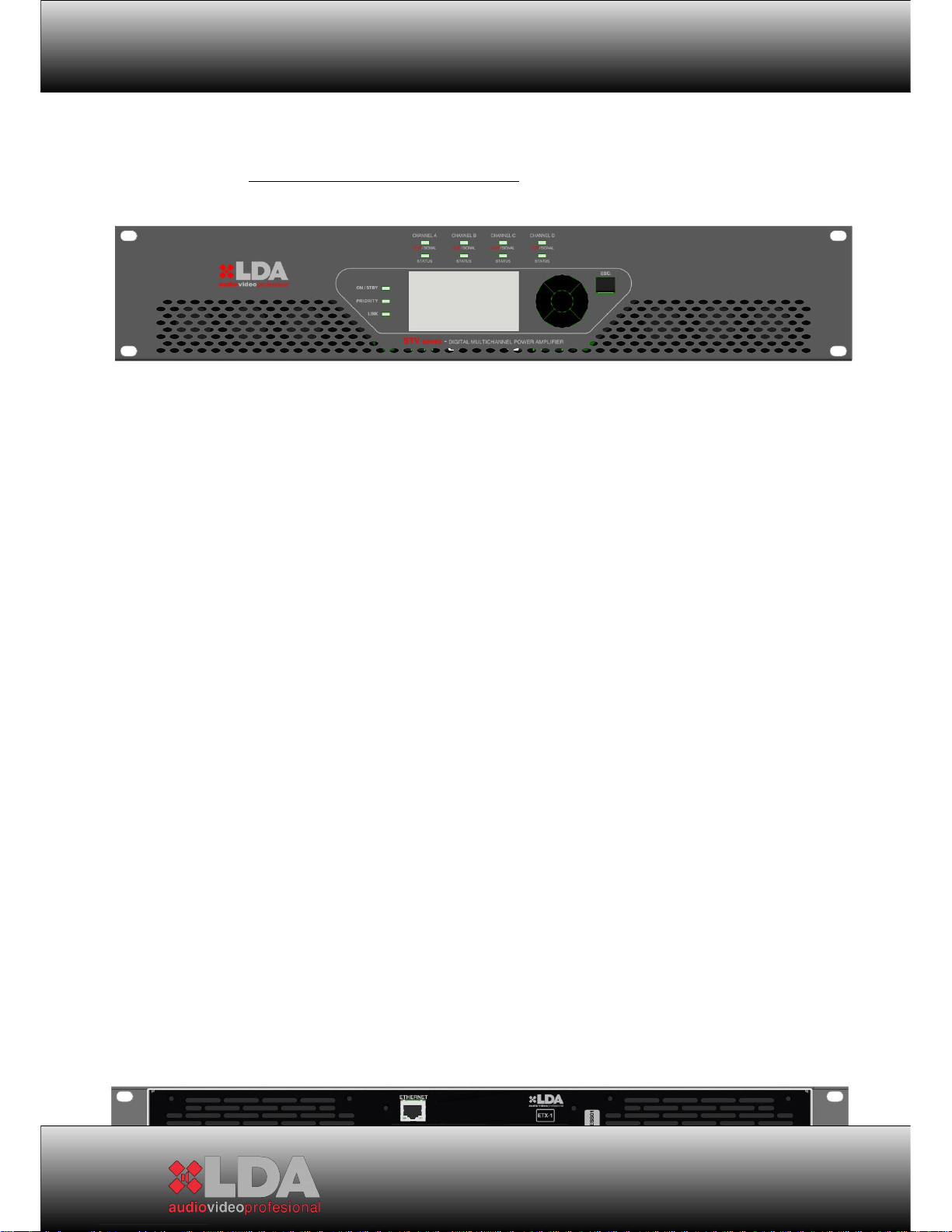
STV SERIES
STV WITH EXPANSION MODULE ETX-1
STV WITH EXPANSION MODULE ETX-1CN
9

USER MANUAL
2 DESCRIPTION OF CONTROLS:
2.1 BEFORE SWITCHING THE DEVICE ON:
1- Make sure that the power supply circuits are properly dimensioned and
that the power voltage is stable. To dimension the circuits, check the
technical characteristics of the specific model.
2- Make sure there is correct air circulation from the front of the device
towards the back, and avoid obstructing the air flow. This device has
forced ventilation at variable speed depending on the dissipation needs,
in order to maintain the best operation temperature. Blocking the air inlets
or outlets can cause overheating of the device. In case of overheating the
system will protect itself by cutting the audio signal until it recovers the
optimum operating temperature.
3- Check that the loudspeaker lines connected to the amplifier channels
exceed the minimum specified impedance for nominal channel power.
10
STV SERIES
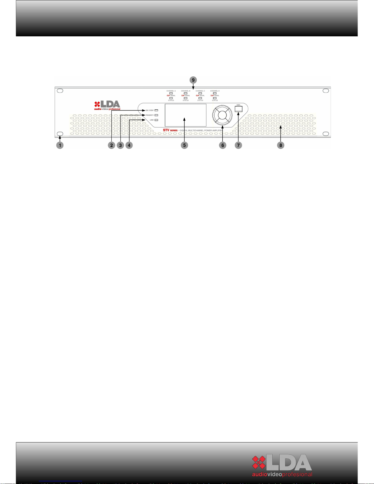
2.2 DESCRIPTION OF CONTROLS. FRONT PANEL:
1- Drill holes for assembly on 19” rack
2- “On / Standby” indicator
“Standby”: The indicator light will be red. In this condition the device will
wait for the amplifier channels to be switched on. The unit’s control and
monitoring elements remain active, allowing the configuration of all the
operation parameters. This state is the same if the device is controlled
remotely through an ETX series expansion module. In this mode, the
level of consumption remains low.
“On”: The indicator light will be green. Before indicating “on”, the amplifier
will check the whole system. If everything is correct, then it will go “on”.
3- “Priority” indicator: In normal operating mode, it will remain switched
off. When the priority audio input is activated, the indicator light will be
green.
4- “Link” indicator: In case the system uses an expansion module of the
ETX series, the light will be orange to indicate that there exists correct
communication with the LDA remote control system.
5- 128x64 LCD Screen: It allows controlling and monitoring the system
locally. It has contrast and intensity control, and also incorporates
dynamic backlighting correction depending on the lighting of the place
where the equipment is located, thus providing optimum display
conditions. It includes screensaver configuration and turn-off timer to save
energy.
6- Navigation control: It consists of five keys, four for direction and one for
confirmation to navigate through the system’s configuration and
monitoring menus. Any parameter that needs to be modified must be
confirmed by pressing the “OK” key.
11

USER MANUAL
7- “ESC.” Navigation Control: The control key for menu back, “ESC”,
allows exiting the selected menu icon when pressed once, and when
pressed consecutively it allows going backwards in the navigation. In
case of parameter modification, as long as the “OK” key has not been
pressed the previous state is recovered by pressing the “ESC” key.
8- Air inlets for forced ventilation of the amplifier channels, and general
temperature of the device
9- “CLIP/SIGNAL” and “STATUS” Channel indicators:
“CLIP/SIGNAL”: Indicates the signal level of audio channel X. A green
light indicates a normal level of audio signal output; an orange light
indicates a high output level, and a red light indicates “CLIP” output
signal.
“STATUS”: Indicates the status of the amplifier channel:
-If the indicator light is red continuously: The amplifier channel is in the
mode due to some problem detected during its operation. In this case,
check that there is no problem of overheating by monitoring the
temperature with the appropriate menu. If the problem is overheating,
check that the connected voltage corresponds to the unit’s specifications,
and that the air inlets/outlets are not blocked or obstructed. If the problem
is not due to overheating, turn the system off by pressing the “power”
button on the back and contact the LDA Authorised Technical Service.
If the indicator light is red intermittently: It indicates a transitory channel
state due to some problem detected in the loudspeaker lines with which
the amplifier channels are loaded. In this case, check that the
loudspeaker lines are not diverted or in short-circuit.
If the indicator light is orange: The amplifier channel does not have any
load, the load is of very high impedance, or the loudspeaker line has an
open-circuit fault.
If the indicator light is green: The amplifier channel is working in optimum
conditions.
12
STV SERIES
2.3 DESCRIPTION OF CONTROLS. CONFIGURATION MENU:
2.3.1
NAVEGATION INDICATORS:
IMPORTANT:
It is necessary press the OK key in order to change the settings. If the
ESC key is pressed, it will return to the previous value. The OK key must be
pressed for selecting the Mode if you are in the Navigation Mode. In another
case, we it would keep in the Navigation Mode between menus.
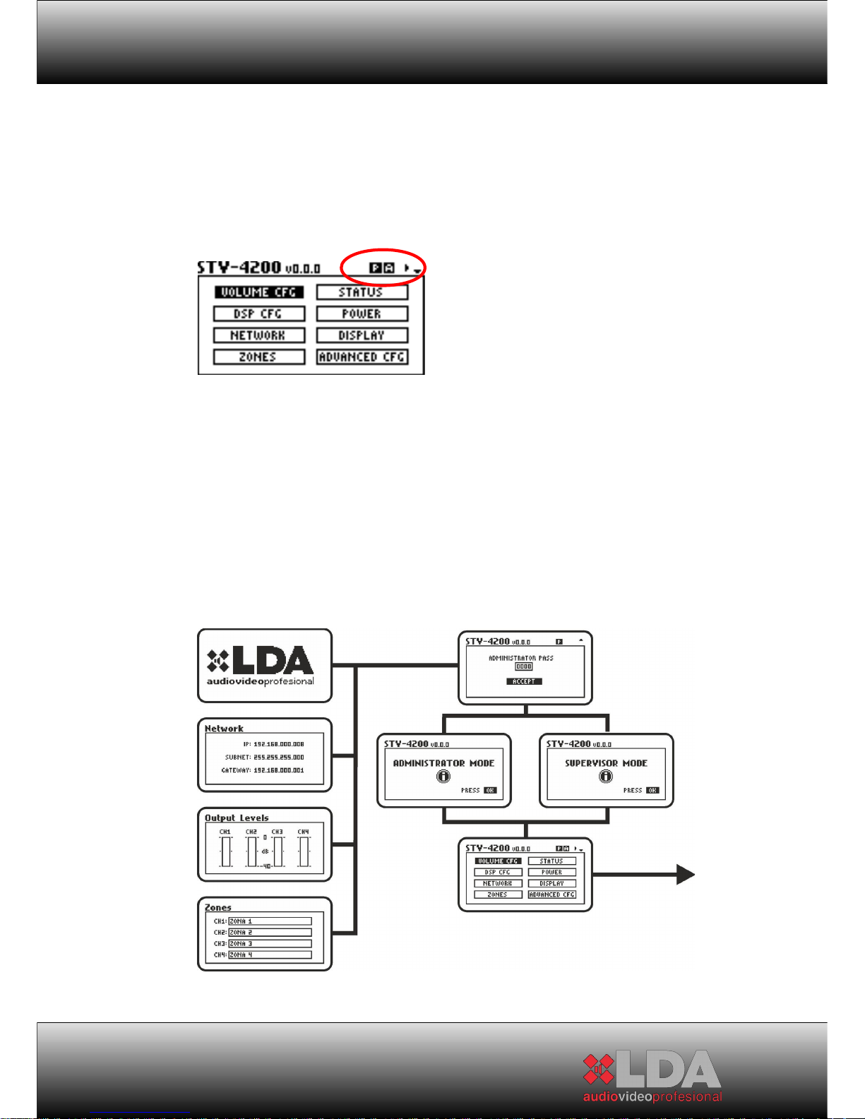
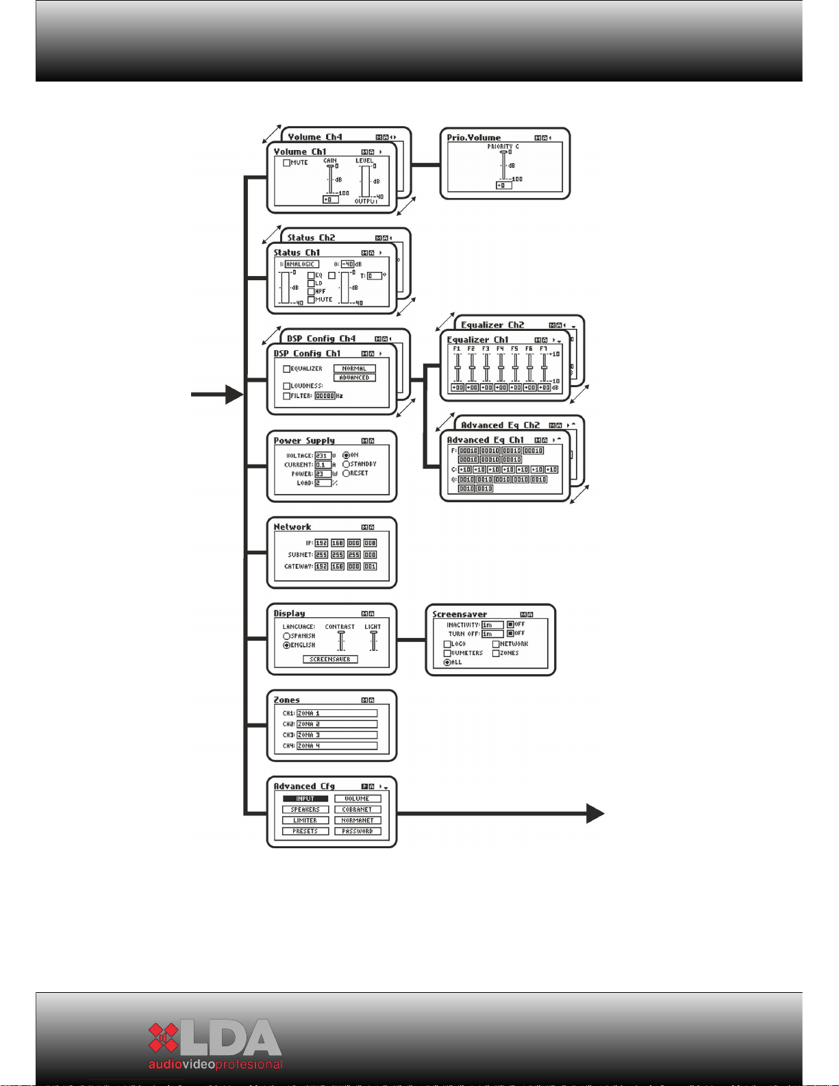
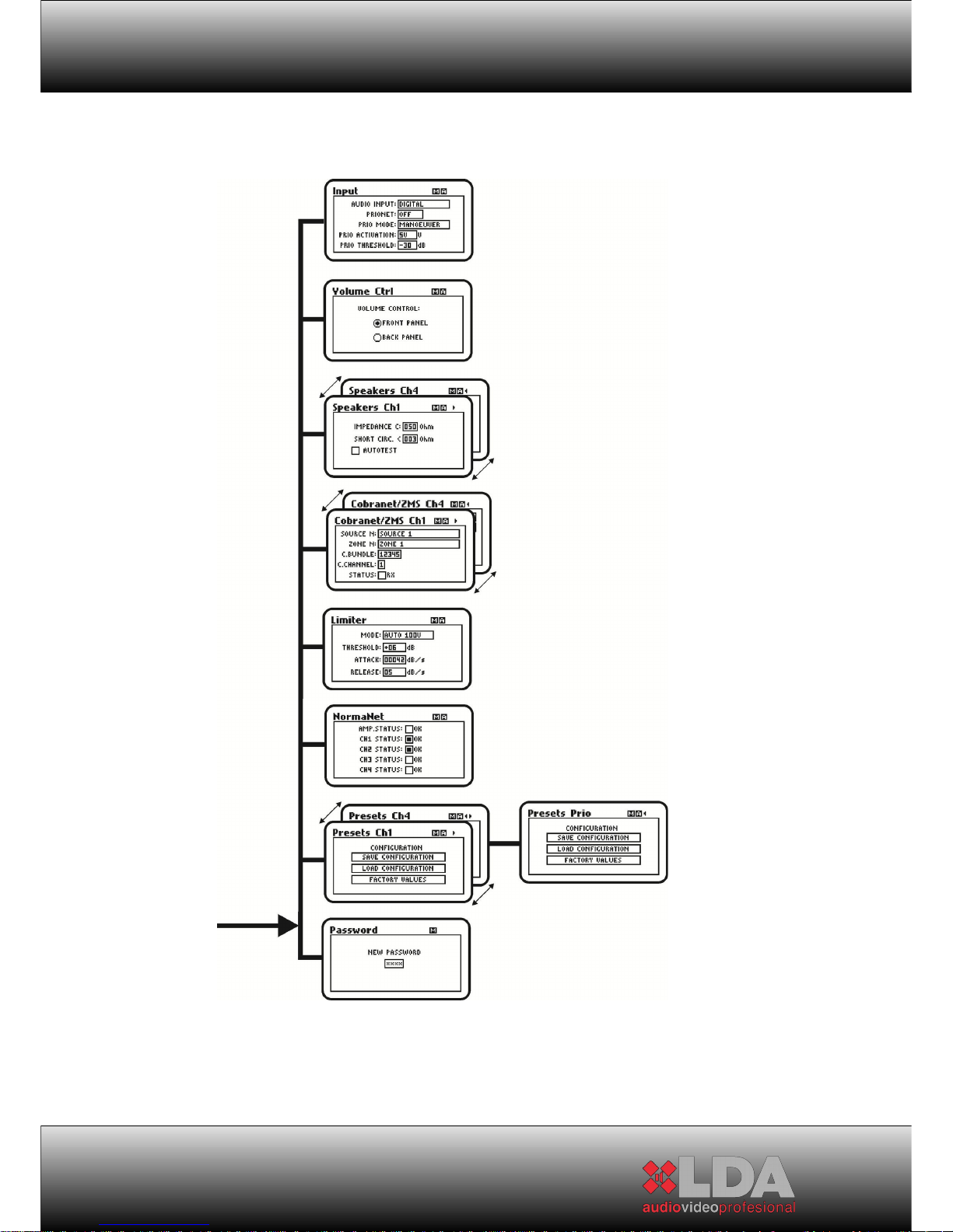
2.3.2
MENU DIAGRAM:
13
USER MANUAL
14
STV SERIES
15
USER MANUAL
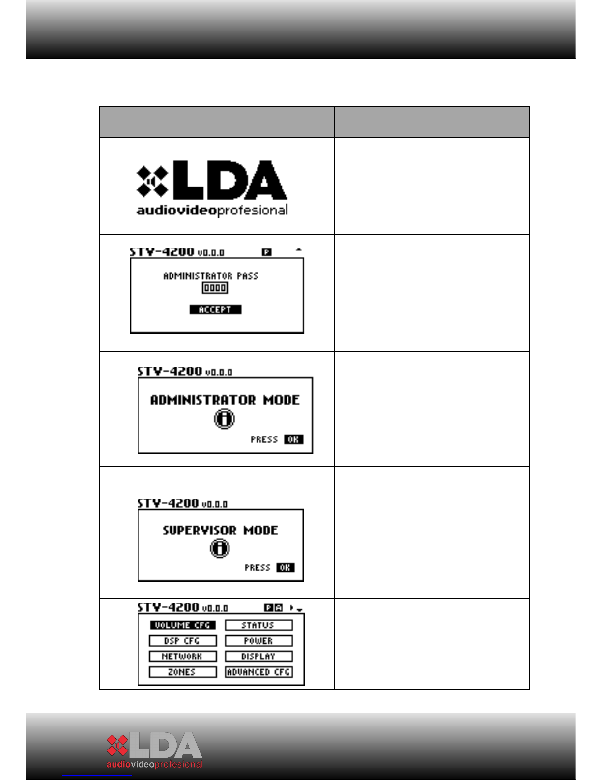
2.3.3
MENU:
Welcome screen: During start-up and
also as default screensaver
User access control. By
default: 0000
Access Information Screen for
Administrator mode. It’s shown if the
password is correct.
Access Information Screen for
Supervisor mode. It’s shown if the
password is correct. The equipment
setting is not allowed in this mode.
Menu to select submenus
16
 Loading...