

Page 1

Page 2

Page 3

STV SERIES
TABLE OF CONTENTS:
1 TECHNICAL DESCRIPTION: .......................................................... 8
2 DESCRIPTION OF CONTROLS: .................................................. 10
2.1 BEFORE SWITCHING THE DEVICE ON: ................................................ 10
2.2 DESCRIPTION OF CONTROLS. FRONT PANEL: .................................. 11
2.3 DESCRIPTION OF CONTROLS. CONFIGURATION MENU: ................. 13
2.3.1 NAVEGATION INDICATORS: ................................................. 13
2.3.2 MENU DIAGRAM: .................................................................... 13
2.3.3 MENU: ...................................................................................... 16
2.4 DESCRIPTION OF CONTROLS. BACK: ................................................. 22
3 CONNECTIONS: ............................................................................ 22
3.1 CONNECTIONS. BACK: ........................................................................... 23
4 working decription: ...................................................................... 26
4.1 PRIORITY INPUT: ..................................................................................... 26
4.2 SETTING BY USB: .................................................................................... 26
4.2.1 DRIVER INSTALLATION: ..................................................................... 26
4.2.2 CONNECTION: ...................................................................................... 27
4.2.3 USB MENUS: ........................................................................................ 28
5 ETX SERIES MODULES: .............................................................. 31
5.1 TECHNICAL DESCRIPTION: ................................................................... 31
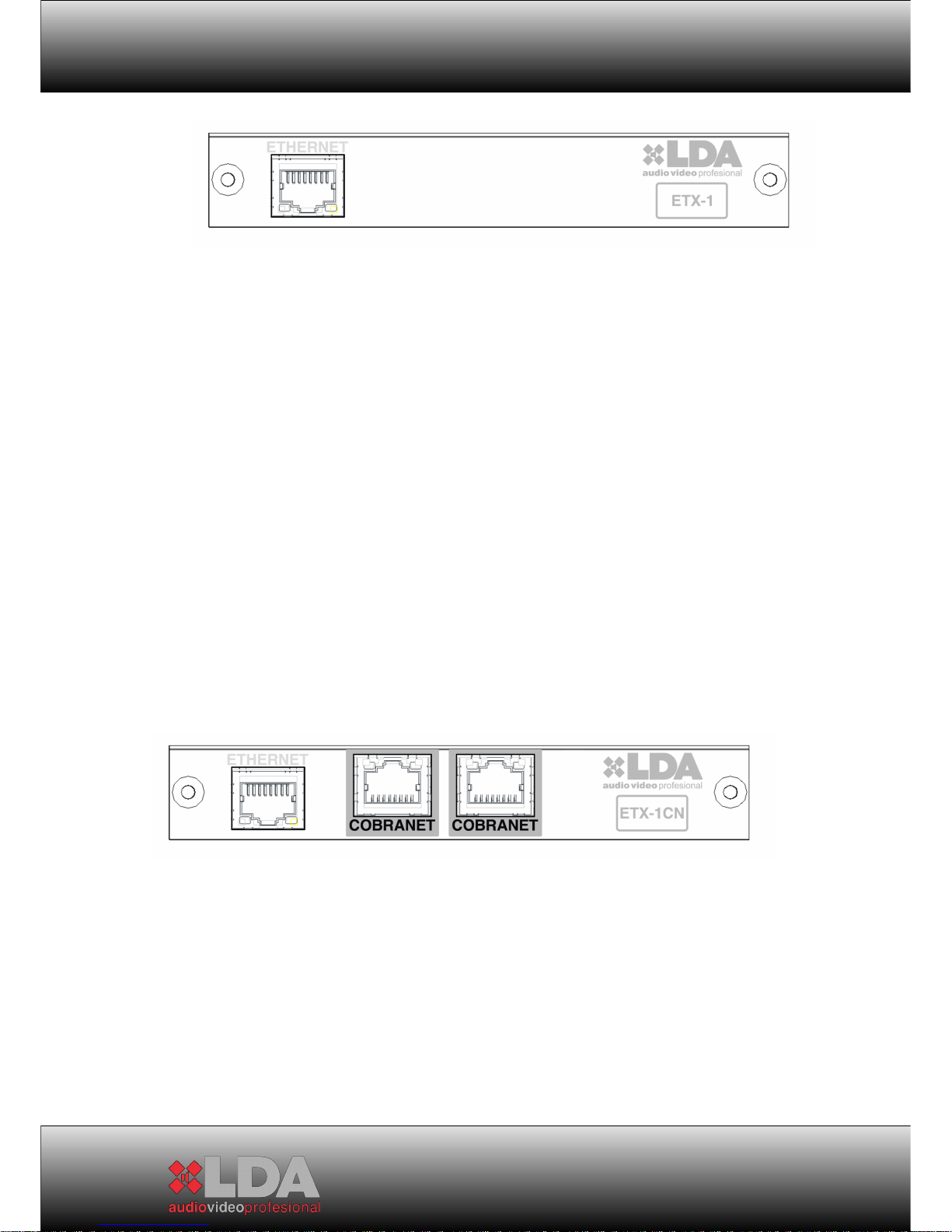
5.1.1 ETX-1 MODULE: ...................................................................... 31
5.1.2 ETX-1CN MODULE: ................................................................. 34
5.2 INSTALLATION OF ETX MODULES: ...................................................... 35
5.3 TECHNICAL SPECIFICATIONS: .............................................................. 37
5.3.1 ETX-1 MODULE: ...................................................................... 38
3
Page 4

USER MANUAL
5.3.2 ETX-1CN MODULE: ................................................................. 39
6 technical specifications: ............................................................. 40
6.1 MECHANICAL CHARACTERISTICS: ...................................................... 40
6.2 GENERAL SPECIFICATIONS: ................................................................. 41
6.3 SPECIFICATIONS DEPENDING ON MODEL: ......................................... 42
7 EQUIPMENT STATUS AND FAILURE MESSAGES ................... 46
8 average time for repairing, MTBF: .............................................. 48
9 NOTES: .......................................................................................... 49
4
Page 5

STV SERIES
5
Page 6

USER MANUAL
WARNINGS:
1. Read this instruction manual before operating the device.
2. Keep this manual for further reference.
3. This device must not be exposed to water. As a precautionary measure,
objects containing liquids must not be placed next to/on top of it.
4. Do not block the system’s ventilation inlets/outlets, and do not install the
device to sources of heat.
5. If the device is going to be mounted on a frame or rack, make sure that
there is good ventilation.
6. Only use original accessories provided by the equipment’s manufacturer.
7. Unplug the device when it is not going to be used for a long period of
time.
8. Clean with a wet cloth, and do not use chemicals products.
6
Page 7

STV SERIES
7
Page 8
USER MANUAL
1 TECHNICAL DESCRIPTION:
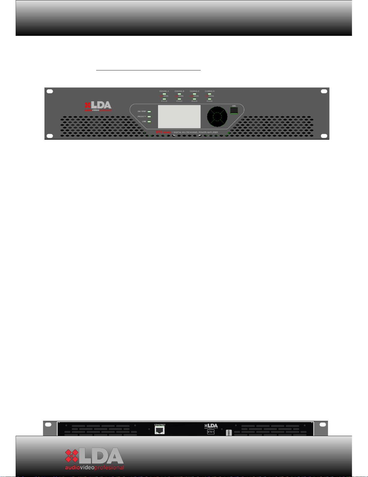
The STV series has amplifiers of 2 and 4 Class AB channels with direct
output (without transformer) at 100V. Available configurations are for 2 200W,
400W or 800W channels, and 4 200W or 400W channels.
Each amplifier channel includes connected loudspeaker line monitor and
protection functions against over-heating, clip and short-circuit, in addition to
forced ventilation at variable speed.
The STV series has a graphical screen on the front panel that allows
configurating operation parameters, and the control and monitoring of the
equipment. It also includes three general indicators: on/standby, link Ethernet
(only for ETX-1 and ETX-1CN), and active priority input, and two indicators per
channel: presence of signal/clip and state of channel (indicates 3 different
states).
All versions comply with standard EN-UNE 60849 regarding voice
evacuation systems, since the operation of the audio channel, from the input to
the output of the amplifier, is monitored with and without input signals to the
system, therefore ensuring that it is available during an emergency.
All models have DSP per channel for audio control. In addition to the 2 or
4 inputs depending on the number of amplifier channels, they also include a
priority input activated by means of an external operation.
The entire series includes an expansion bay to assemble remote control
and monitoring modules through Ethernet (ETX-1), or direct audio inputs
through CobraNet (ETX-1CN). This module also includes the features of model
ETX-1.
The dimensions of all products are the same for all possible channel
configurations, and can be installed on 2 19” rack units.
8
Page 9

STV SERIES
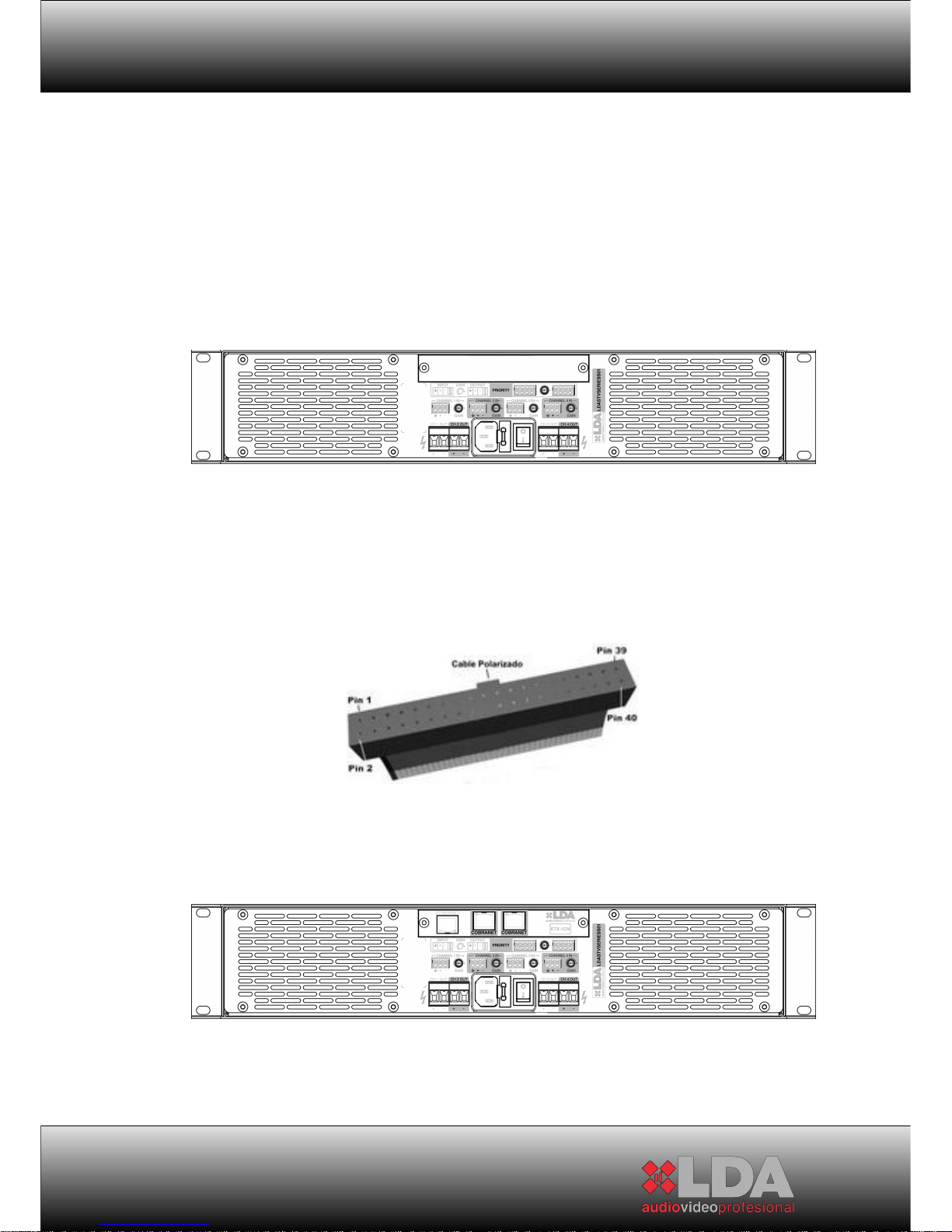
STV WITH EXPANSION MODULE ETX-1
STV WITH EXPANSION MODULE ETX-1CN
9
Page 10

USER MANUAL
2 DESCRIPTION OF CONTROLS:
2.1 BEFORE SWITCHING THE DEVICE ON:
1- Make sure that the power supply circuits are properly dimensioned and
that the power voltage is stable. To dimension the circuits, check the
technical characteristics of the specific model.
2- Make sure there is correct air circulation from the front of the device
towards the back, and avoid obstructing the air flow. This device has
forced ventilation at variable speed depending on the dissipation needs,
in order to maintain the best operation temperature. Blocking the air inlets
or outlets can cause overheating of the device. In case of overheating the
system will protect itself by cutting the audio signal until it recovers the
optimum operating temperature.
3- Check that the loudspeaker lines connected to the amplifier channels
exceed the minimum specified impedance for nominal channel power.
10
Page 11
STV SERIES
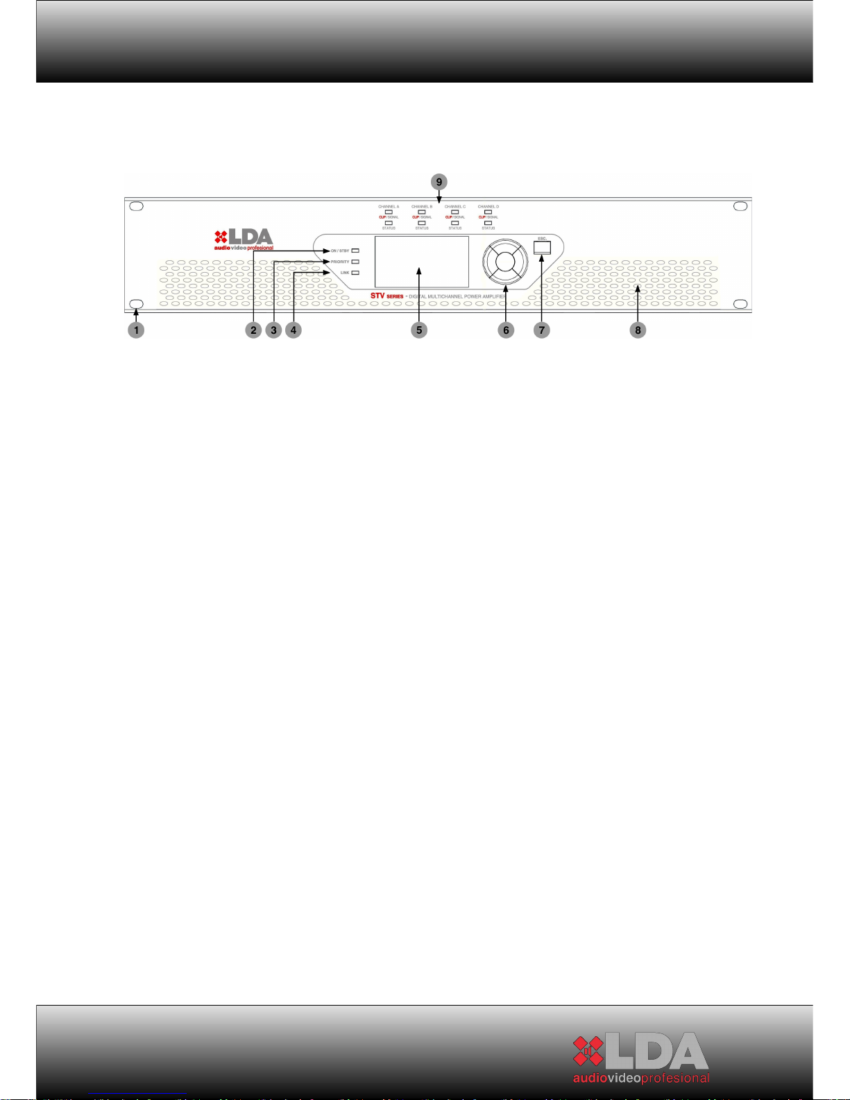
2.2 DESCRIPTION OF CONTROLS. FRONT PANEL:
1- Drill holes for assembly on 19” rack
2- “On / Standby” indicator
“Standby”: The indicator light will be red. In this condition the device will
wait for the amplifier channels to be switched on. The unit’s control and
monitoring elements remain active, allowing the configuration of all the
operation parameters. This state is the same if the device is controlled
remotely through an ETX series expansion module. In this mode, the
level of consumption remains low.
“On”: The indicator light will be green. Before indicating “on”, the amplifier
will check the whole system. If everything is correct, then it will go “on”.
3- “Priority” indicator: In normal operating mode, it will remain switched
off. When the priority audio input is activated, the indicator light will be
green.
4- “Link” indicator: In case the system uses an expansion module of the
ETX series, the light will be orange to indicate that there exists correct
communication with the LDA remote control system.
5- 128x64 LCD Screen: It allows controlling and monitoring the system
locally. It has contrast and intensity control, and also incorporates
dynamic backlighting correction depending on the lighting of the place
where the equipment is located, thus providing optimum display
conditions. It includes screensaver configuration and turn-off timer to save
energy.
6- Navigation control: It consists of five keys, four for direction and one for
confirmation to navigate through the system’s configuration and
monitoring menus. Any parameter that needs to be modified must be
confirmed by pressing the “OK” key.
11
Page 12

USER MANUAL
7- “ESC.” Navigation Control: The control key for menu back, “ESC”,
allows exiting the selected menu icon when pressed once, and when
pressed consecutively it allows going backwards in the navigation. In
case of parameter modification, as long as the “OK” key has not been
pressed the previous state is recovered by pressing the “ESC” key.
8- Air inlets for forced ventilation of the amplifier channels, and general
temperature of the device
9- “CLIP/SIGNAL” and “STATUS” Channel indicators:
“CLIP/SIGNAL”: Indicates the signal level of audio channel X. A green
light indicates a normal level of audio signal output; an orange light
indicates a high output level, and a red light indicates “CLIP” output
signal.
“STATUS”: Indicates the status of the amplifier channel:
-If the indicator light is red continuously: The amplifier channel is in the
mode due to some problem detected during its operation. In this case,
check that there is no problem of overheating by monitoring the
temperature with the appropriate menu. If the problem is overheating,
check that the connected voltage corresponds to the unit’s specifications,
and that the air inlets/outlets are not blocked or obstructed. If the problem
is not due to overheating, turn the system off by pressing the “power”
button on the back and contact the LDA Authorised Technical Service.
If the indicator light is red intermittently: It indicates a transitory channel
state due to some problem detected in the loudspeaker lines with which
the amplifier channels are loaded. In this case, check that the
loudspeaker lines are not diverted or in short-circuit.
If the indicator light is orange: The amplifier channel does not have any
load, the load is of very high impedance, or the loudspeaker line has an
open-circuit fault.
If the indicator light is green: The amplifier channel is working in optimum
conditions.
12
Page 13
STV SERIES
2.3 DESCRIPTION OF CONTROLS. CONFIGURATION MENU:
2.3.1
NAVEGATION INDICATORS:
IMPORTANT:
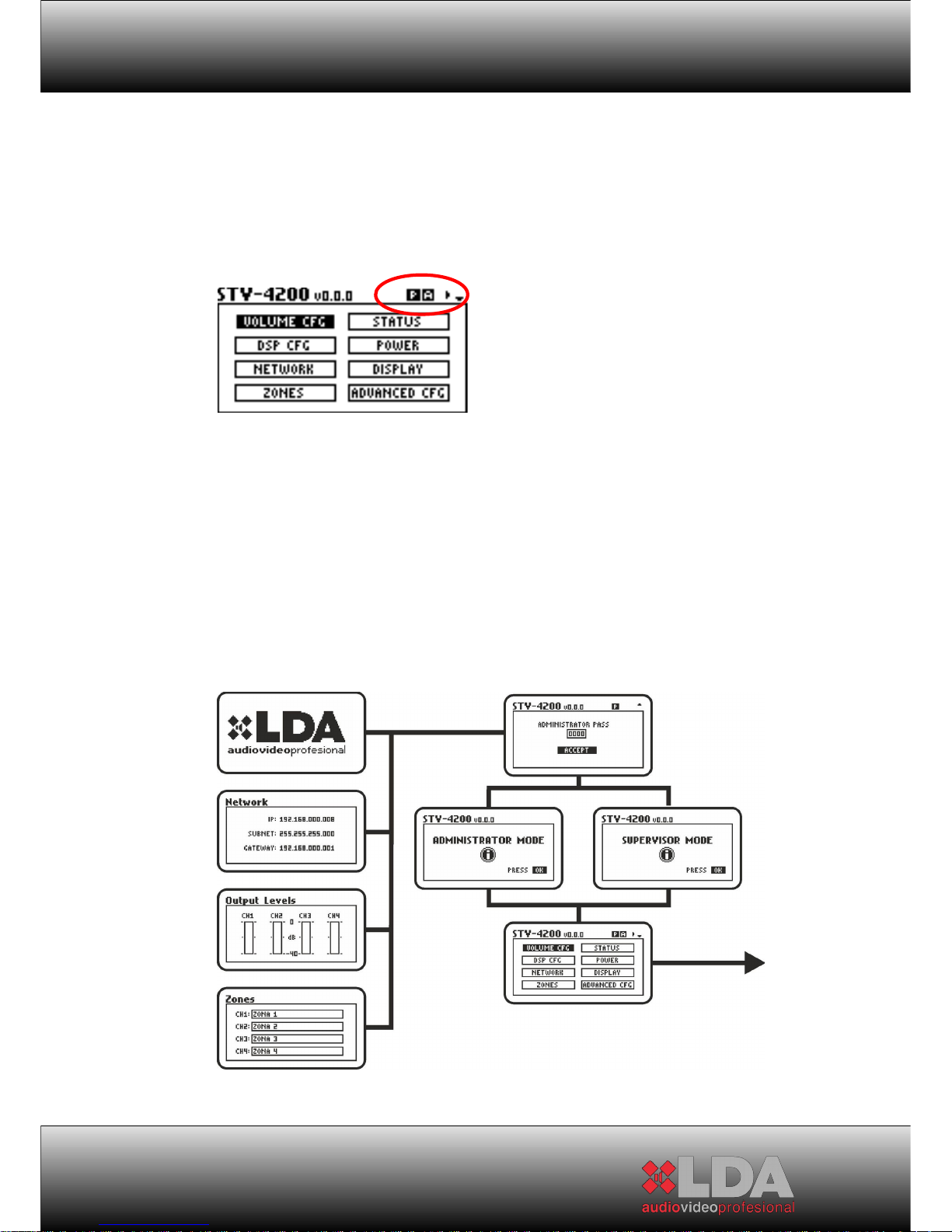
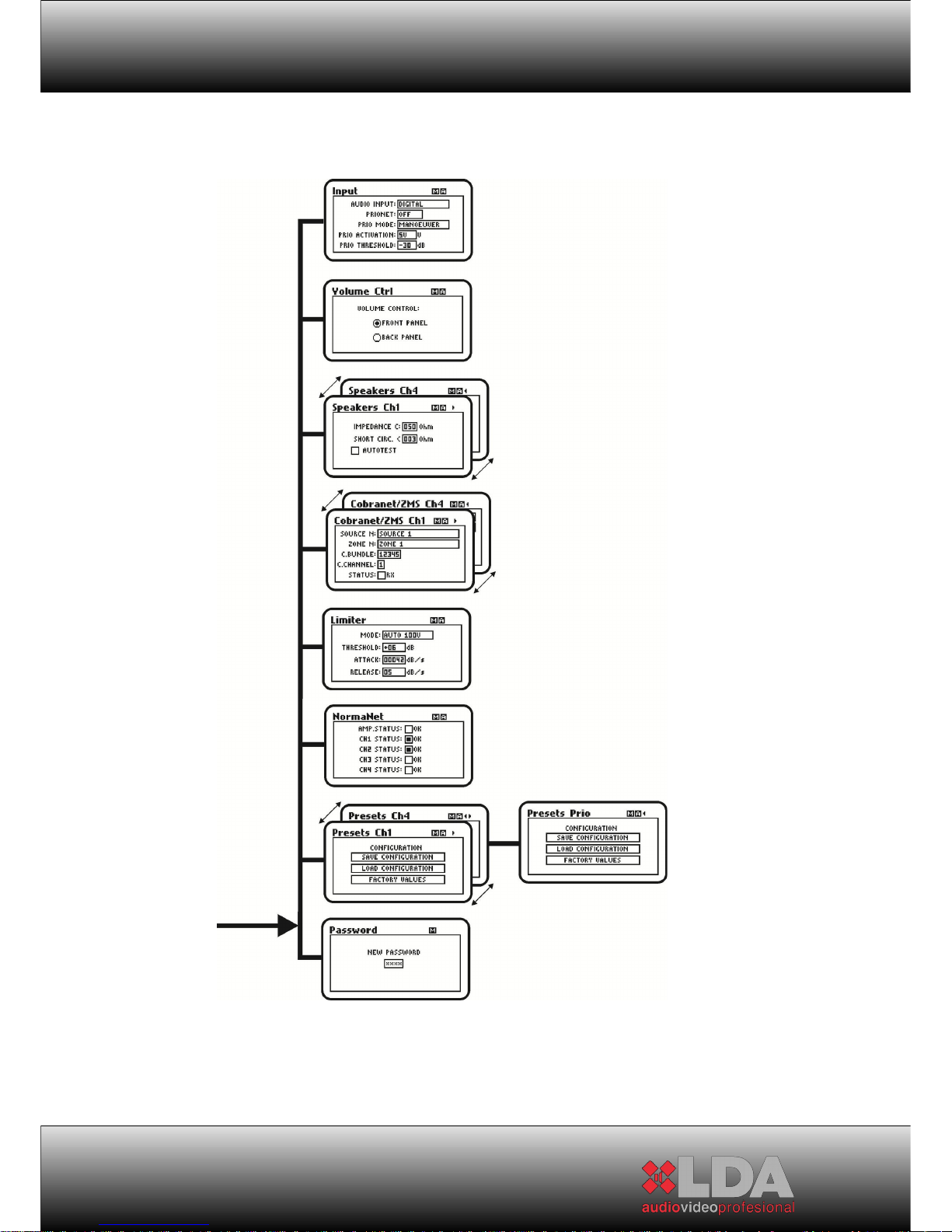
It is necessary press the OK key in order to change the settings. If the
ESC key is pressed, it will return to the previous value. The OK key must be
pressed for selecting the Mode if you are in the Navigation Mode. In another
case, we it would keep in the Navigation Mode between menus.
2.3.2
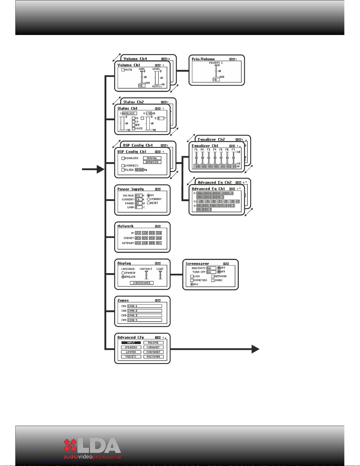
MENU DIAGRAM:
13
Page 14
USER MANUAL
14
Page 15
STV SERIES
15
Page 16
USER MANUAL
2.3.3
MENU:
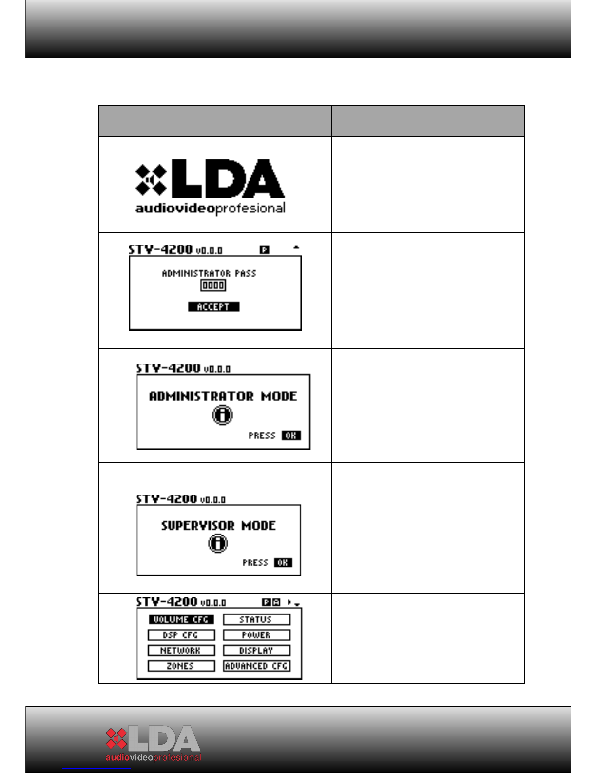
Welcome screen: During start-up and
also as default screensaver
User access control. By
default: 0000
Access Information Screen for
Administrator mode. It’s shown if the
password is correct.
Access Information Screen for
Supervisor mode. It’s shown if the
password is correct. The equipment
setting is not allowed in this mode.
Menu to select submenus
16
Page 17
STV SERIES
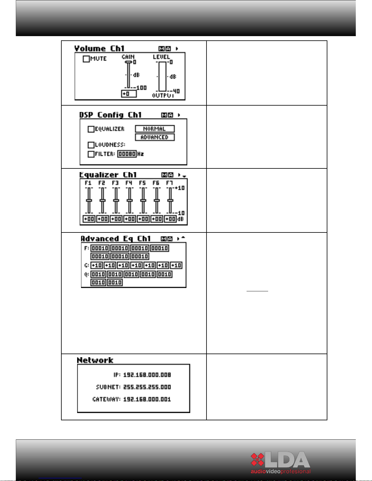
Gain and VU meter control:
It has amplifier channel volume
control for both normal input and to
adjust the priority input level. It also
includes output signal VU meter and
mute indicator.
It allows access to the submenu for
preset 7 band equalization, or to the
advanced equalizer. It also includes a
control to activate a high-pass filter
for low frequencies and “loudness”
Gain set of 7 prefixed bands
Equalizer. The adjustment of
parameters could be made by means
of Advanced Equalizer.
Central Frequency in Hz
Gain measured in dB, Q times.
Advanced Equalizer per
channel. It allows a personalized
adjustment for each band. After band
setting, the gain adjustment could be
configured, which is by default:
Q
fcBw*100
=
Q: Relative Constant of
bandwidth for the filter:
LAN Configuration. This menu is only
available if the system has an ETX
series module.
17
Page 18
USER MANUAL
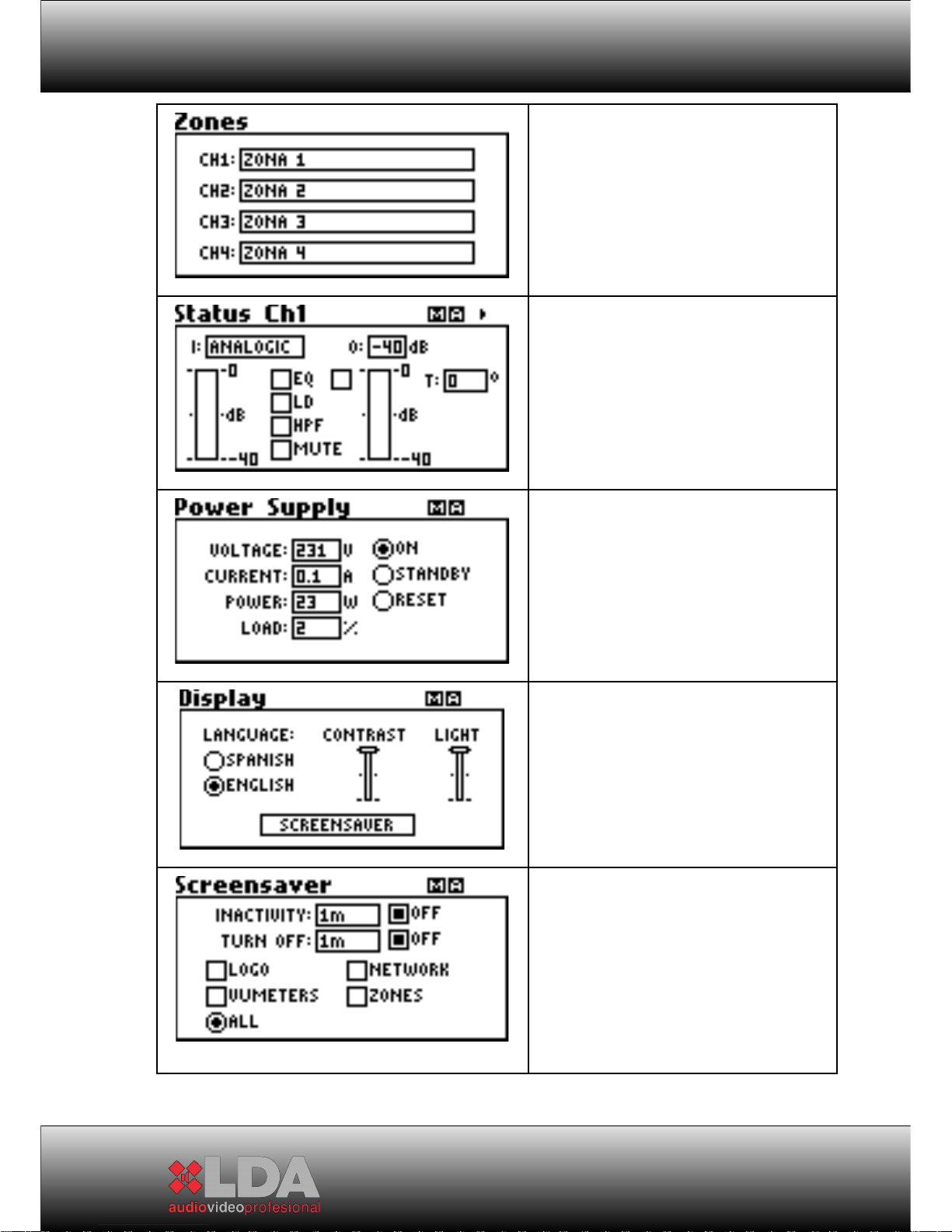
The name of the associated
zone with an amplifier channel is
shown. Available only for ETX
modules.
Channel monitor: It shows all the
information regarding the amplifier
channel selected: type of input, line
voltage, equalizer, loudness, highpass filter, limiter and amplifier
channel temperature.
Main power supply monitor: It shows
the voltage supplied to the system,
as well as consumption in amperes
and watts. It also indicates the
general load of the power supply
source.
Switch On/ Standby Control
Screen Setting Menu. Select
the language, brightness/contrast
adjustment. Access to Screensaver
setting.
Screensaver Setting. It allows
to set the screensaver release time
due to long time without action over
front buttons. The time without action
could be adjusted (total turned
screen off). The information shown
could be selected.
18
Page 19
STV SERIES
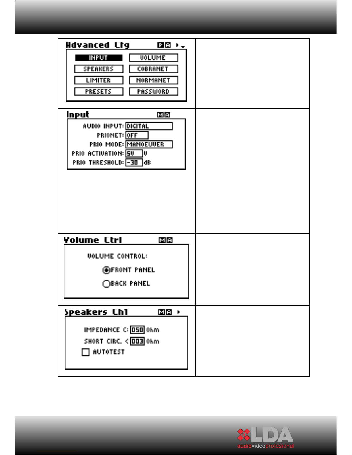
Menu to select advanced
configurations.
Inputs setting.
Analogical/digital audio input
selection – by rear inputs or
CobraNetTM 1 .
1
Available only with ETX-1CN
modules.
PRIONET: Priority Input by
CobraNet –only with ETX-1CN.
MODE: Priority Activation
mode selected by manoeuvre or
noise port.
Volume Controls selection by
volume controls placed into rear
panel or by front control.
Line Speaker setting and
release conditions.
19
Page 20
USER MANUAL
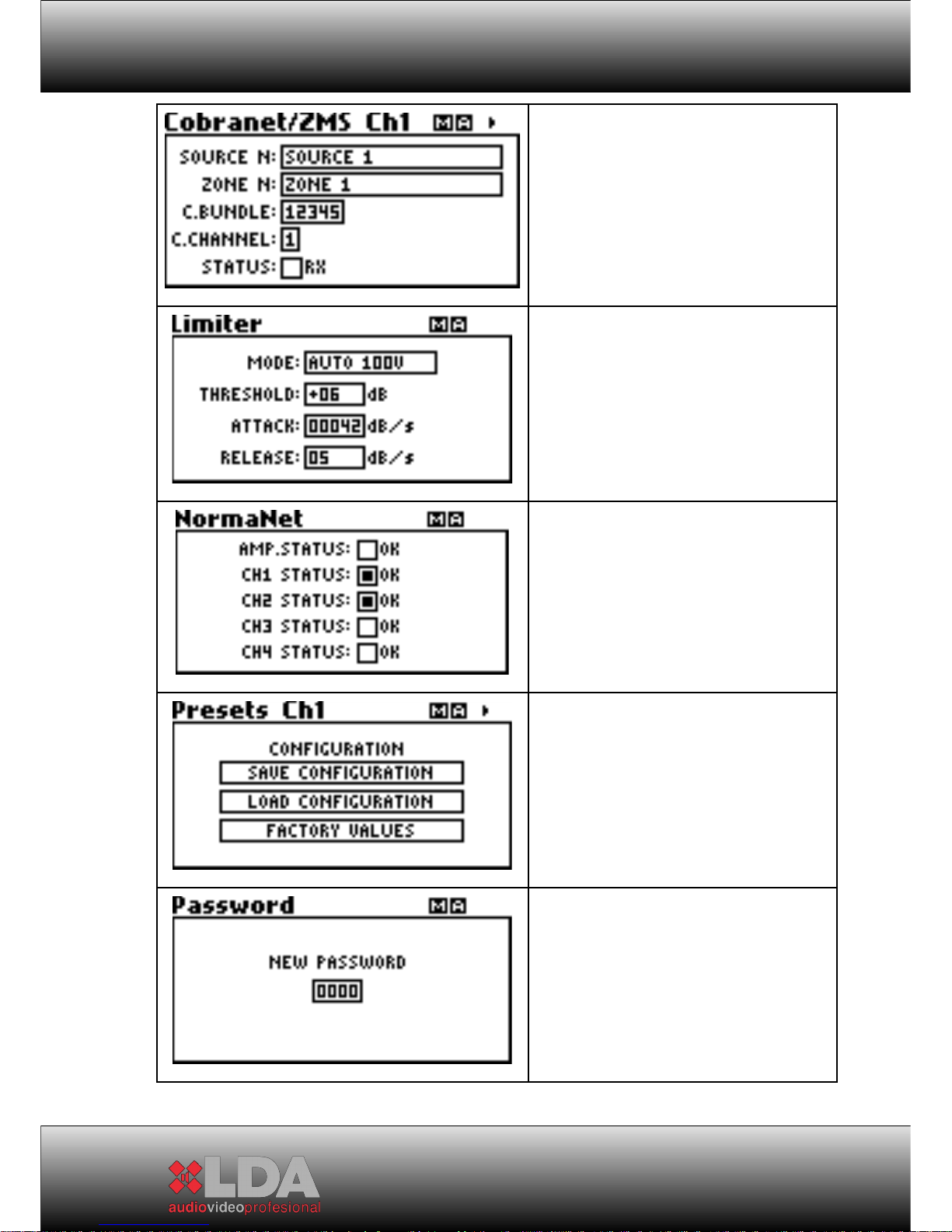
Setting of CobraNet Channels.
Supply name and Zone name are
synchronized automatically by ZMS
System application. The Bundle and
Channel are set per channel.
Anti-clip function Setting.
Modes: 100V or 70V output. The
activation parameters could be set
too.
Equipment status
Checking. It checks the amplifier
channels status.
Access to Save/Load Preset
per channel including Priority Input. It
allows to save the current
configuration status or to recover the
previous status. The default values
per channel could be load.
Change of Access Password
in Administrator model. By default:
0000
20
Page 21
STV SERIES
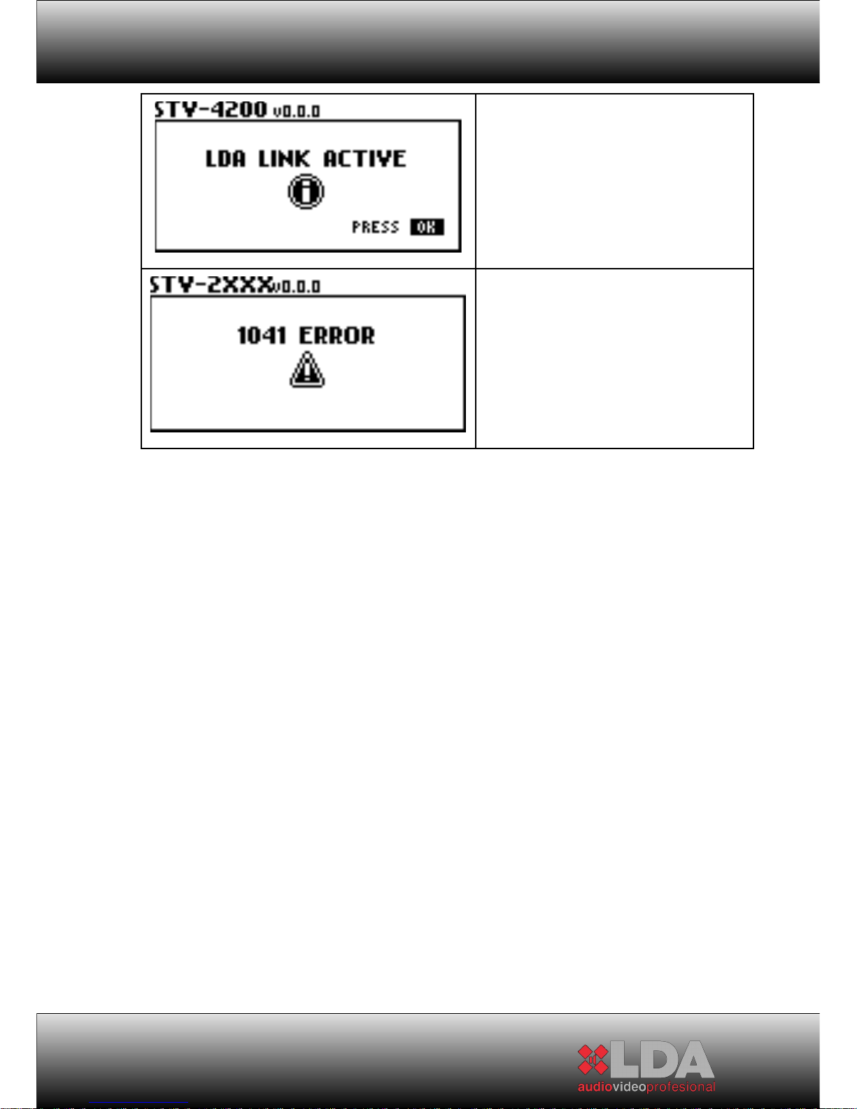
Warning Screen about link
with System Control. The
Administrator Control will be disabled
during remote control. This screen
will be shown to try the access to
Administrator control.
Warning Screen for failure detected.
See section 6 for further information.
21
Page 22
USER MANUAL
2.4 DESCRIPTION OF CONTROLS. BACK:
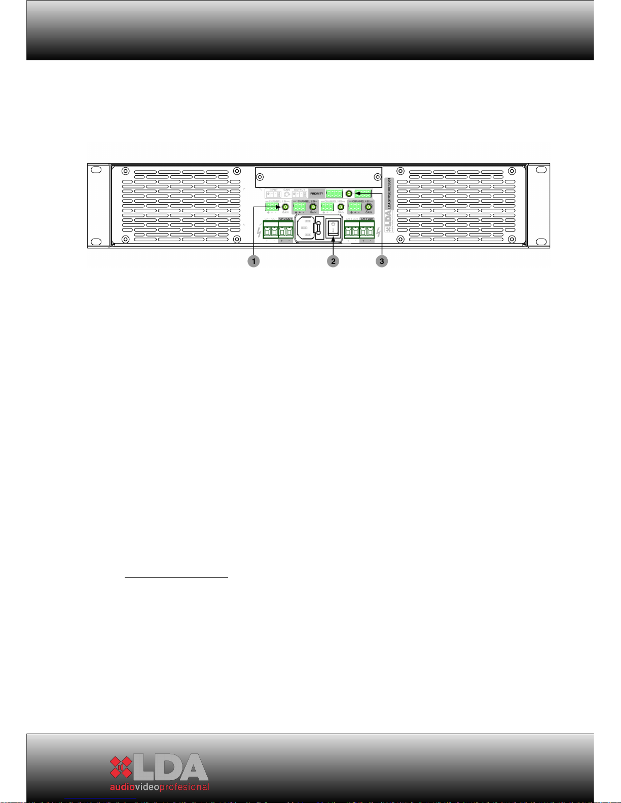
1- Gain Controls: The independent channel gain controls can be adjusted
manually and intuitively from the back. The adjustment range from the
back is comprised between -80dB to 0dB. These controls are set with the
default value and can be disabled in order to perform gain control from
the front panel by using the appropriate adjustment menu. The
adjustment range is comprised between -100dB to 0dB.
2- “Power” Switch: It allows connecting/disconnecting the system
completely from the power supply network. This switch cuts the total
supply directly. The "Clic" sound, which is due to the speakers
connection, can be avoid changing the equipment status to STAND-BY
from the front before turn off the switch.
3- Priority Gain Control: With this control the gain of the priority channel
can be adjusted independently. The adjustment range from the back is
comprised between -80dB to 0dB. Its variation does not affect cascade
priority output. This control is set with a default value and can be disabled
in order to perform gain control from the front panel by using the
appropriate adjustment menu. The adjustment range is comprised
between -100dB to 0dB.
3 CONNECTIONS:
All connectors needed to connect the equipment are supplied. They are
all easily connected and do not need specific tools. 2.5mm and 5mm flat-blade
screwdrivers will be necessary. Next to each type of connection there appears a
descriptive image as a reminder of the correct way to do the connection.
22
Page 23
STV SERIES
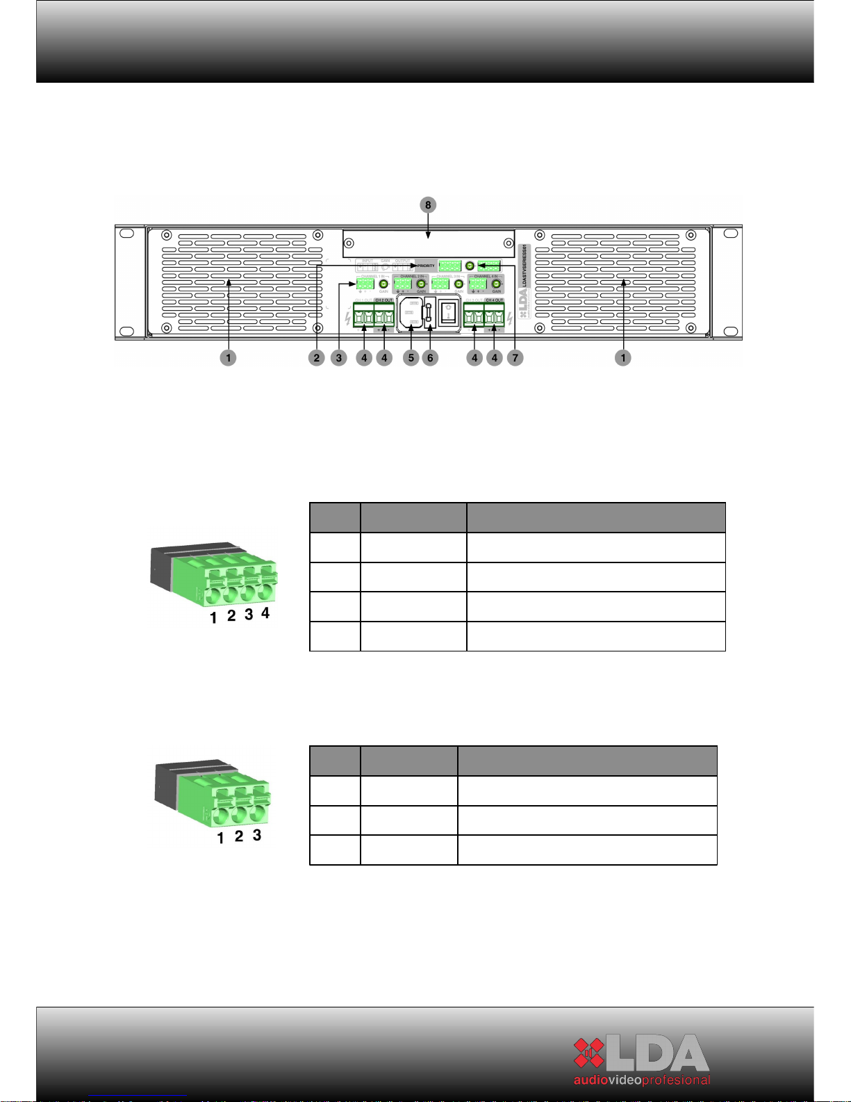
3.1 CONNECTIONS. BACK:
1- Air outlets for forced ventilation of the amplifier channels, and general
temperature of the system
2- Balanced priority audio input:
3.- Balanced audio input channel 1 ,2 ,3 ,4:
23
PIN
SIGNAL DESCRIPTION
1 SHIELD Must always be connected
2 AUDIO+ Input impedance 10 KΩ
3 AUDIO- Input impedance 10 KΩ
4
OPERATION
Active due to closure with pin 1
PIN
SIGNAL DESCRIPTION
1 SHIELD Must always be connected
2 AUDIO+ Input impedance 10 KΩ
3 AUDIO- Input impedance 10 KΩ
Page 24
USER MANUAL
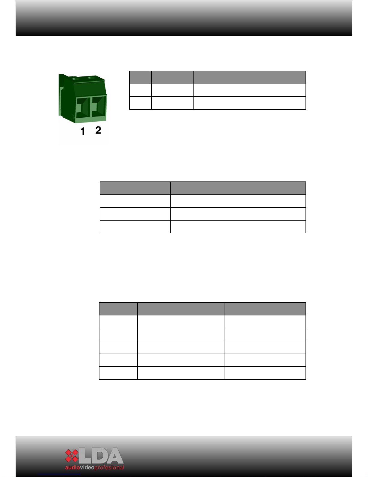
4.- Amplifier channel output:
5- IEC Power Supply Input: All STV series devices have standard IEC
power supply input. The cable with an IEC female connector is supplied
with the device.
6- Fuse: The STV amplifiers have a fuse next to the turn-on switch. A
spare part is supplied inside the fuse holder.
24
PIN
SIGNAL DESCRIPTION
1 + OUTPUT @ 100V POSITIVE
2 - OUTPUT @ 100V NEGATIVE
CHANNEL POWER
MINIMUM IMPEDANCE OF LINE
200 W 50 Ω
400 W 25 Ω
800 W 12.5 - Ω
MODEL OUTPUT POWER FUSE
STV-2200
2x200W 3 AT 250V
STV-4200
4x200 W 5 AT 250V
STV-2400
2x400 W 5 AT 250V
STV-4400
4x400 W 10 AT 250V
STV-2800
2x800 W 10 AT 250V
Page 25
STV SERIES
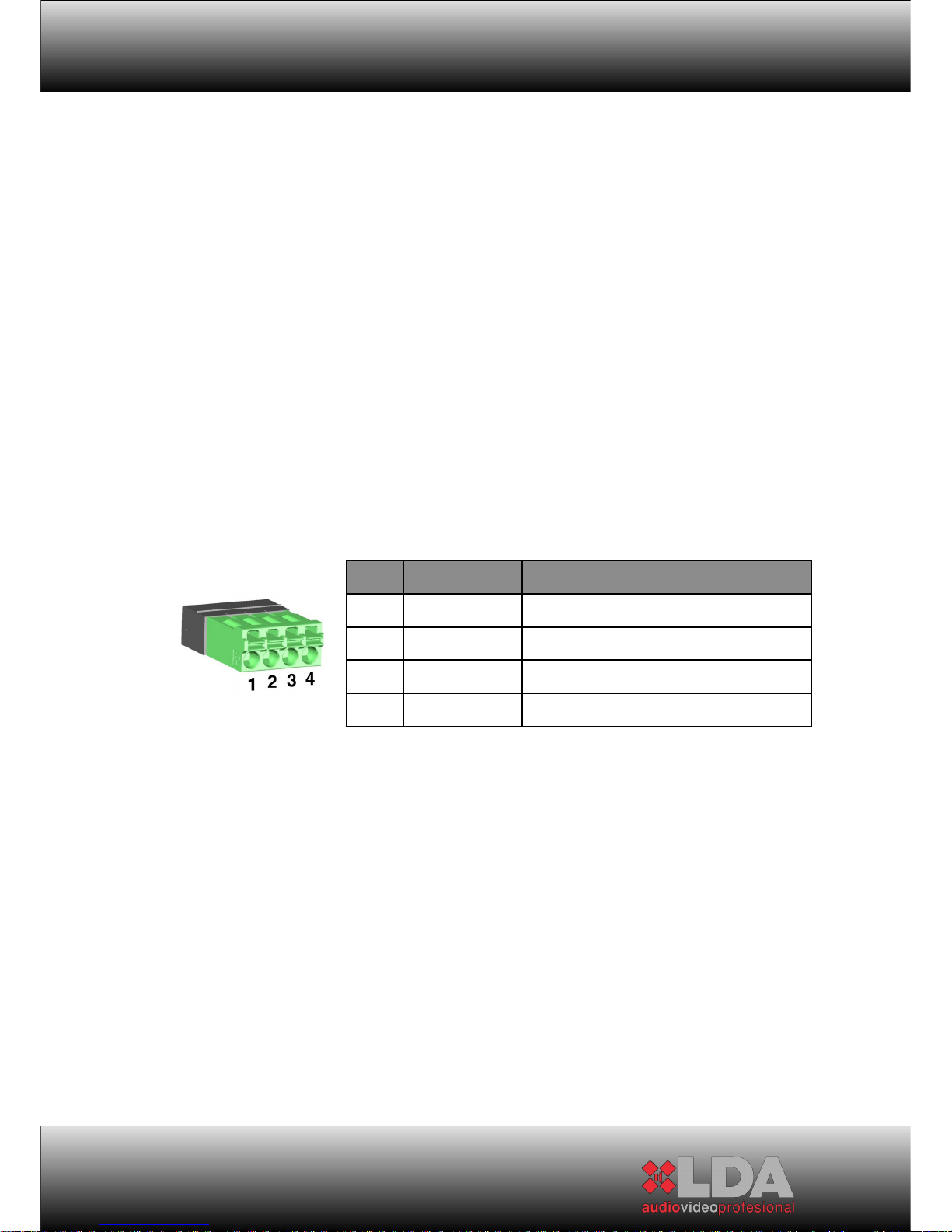
7.- Balanced priority audio output: Regenerated priority audio signal. Both
the audio and the operation are regenerated to connect several systems
in cascade. If the system is switched off, it directly allows priority input to
pass.
8- Expansion bay for connection of ETX series modules
25
PIN
SIGNAL DESCRIPTION
1 SHIELD Must always be connected
2 AUDIO+ Output impedance 100 Ω
3 AUDIO- Input impedance 100 Ω
4
OPERATION
Output impedance 220 Ω
Page 26

USER MANUAL
4 WORKING DECRIPTION:
4.1 PRIORITY INPUT:
The amplifiers of STV series include a priority input, at least, which is activated
by means of manoeuvre or by noise-door -- setting threshold--. If the priority
input is activated, the Priority indicator shows it from the front panel. At this
moment, all amplifiers channels conmute with this input. Then, these channels
will return to the previous status if the shoot condition turns to Stand-by.
If the amplifier of STV series has got an ETX-1CN module placed in, it will have
two priority inputs. One of these inputs is the same which is described below
and the another one is due to CobraNetTM, where all the channels will conmute
with if the audio signal is detected. The channels will return into their previous
status when the condition be on Stand-by. The priority levels are selected from
the most priority to the less priority, they are Priority Input, Priority Input via
CobraNet TM and audio input for the corresponding channel.
4.2 SETTING BY USB:
STV series amplifiers have a USB port in order to make easy the parameters
setting. The setting interface needs the Driver required for each Operative
System -- MICROSOFT WINDOWS XP / VISTA / 7 (32bit) / 7 (64bit)--.
4.2.1 DRIVER INSTALLATION:
The equipment must be connected to the PC firstly, then, a message will be
shown for browsing the Driver location. The file name is LDAVirualCOM.inf.
Follow the next steps to finish the installation.
26
Page 27
STV SERIES
4.2.2 CONNECTION:
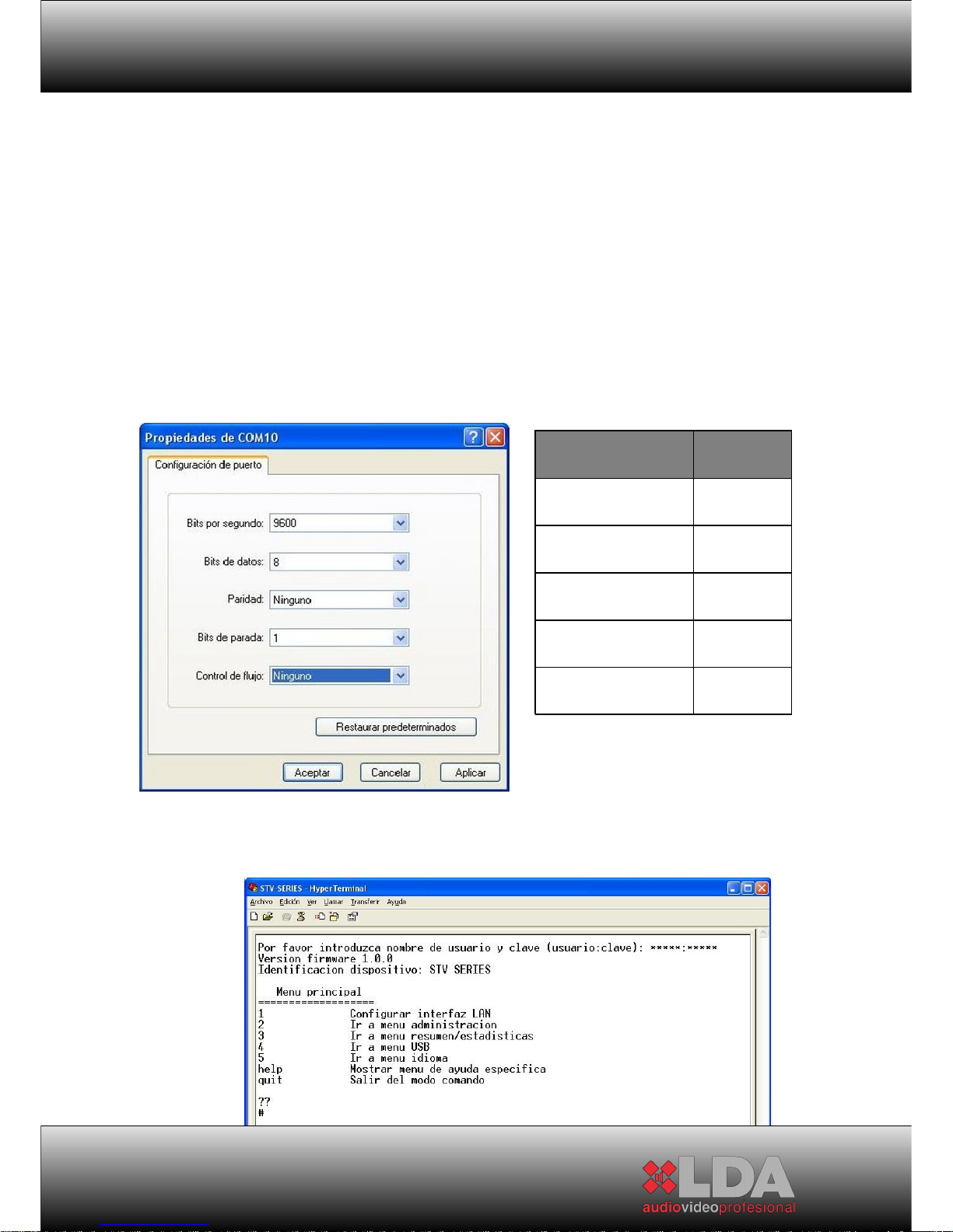
After the driver installation, it is needed a Communication Software like Hyper
Terminal, Hercules, Tera, Term or another for communicating by series port.
The virtual series port of the equipment must has the following setting:
After connection setting it can be established. The following screen will be
shown at the beginning:
27
PARÁMETER VALOR
Speed 9600 bps
Data Bits 8
Parity NO
Bits of Stop 1
Flux Control NO
Page 28
USER MANUAL
The user name is ADMIN and the password is the same which was set
for the Administrator in the equipment. Default value 0000. Both items must be
written with a ":" between them. For instance: ADMIN:0000
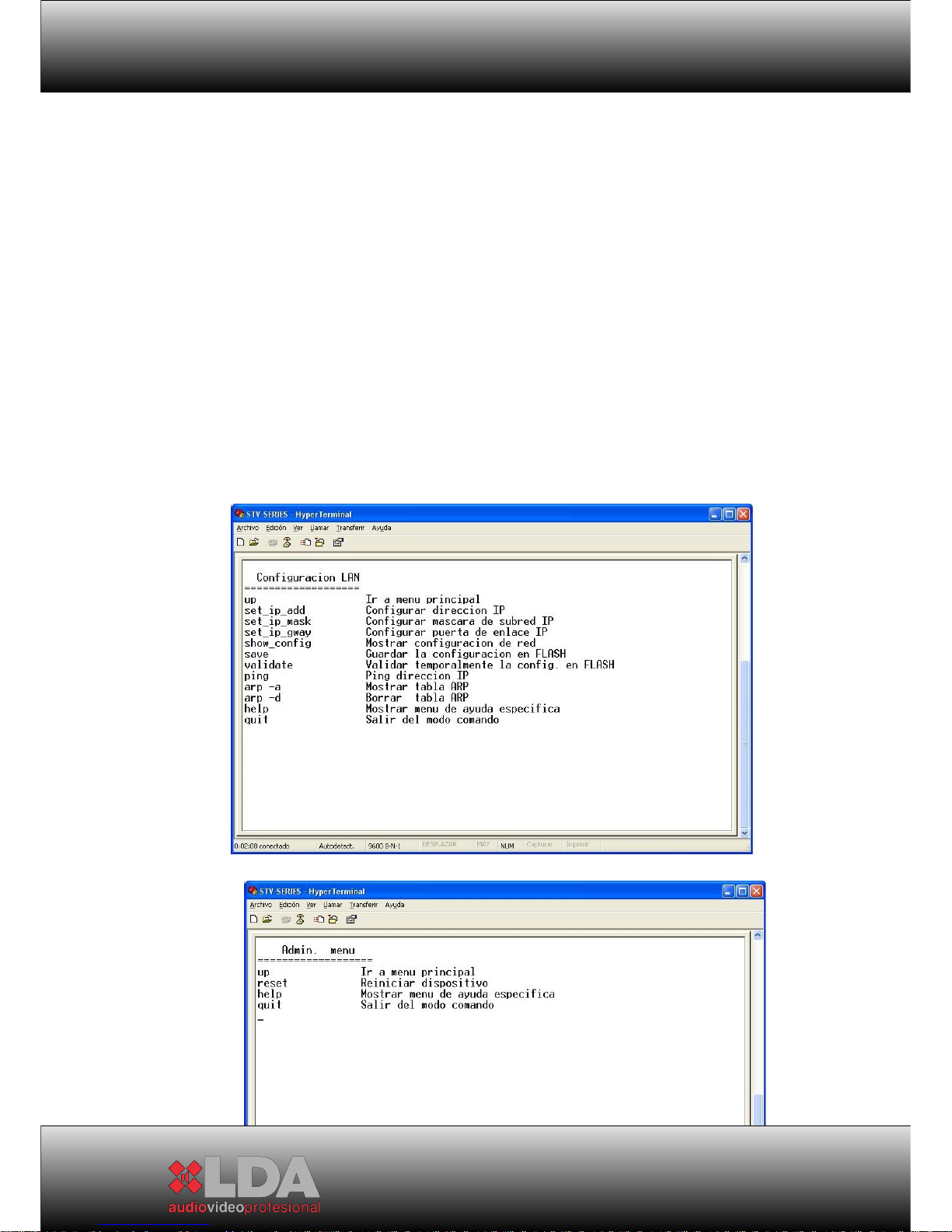
4.2.3 USB MENUS:
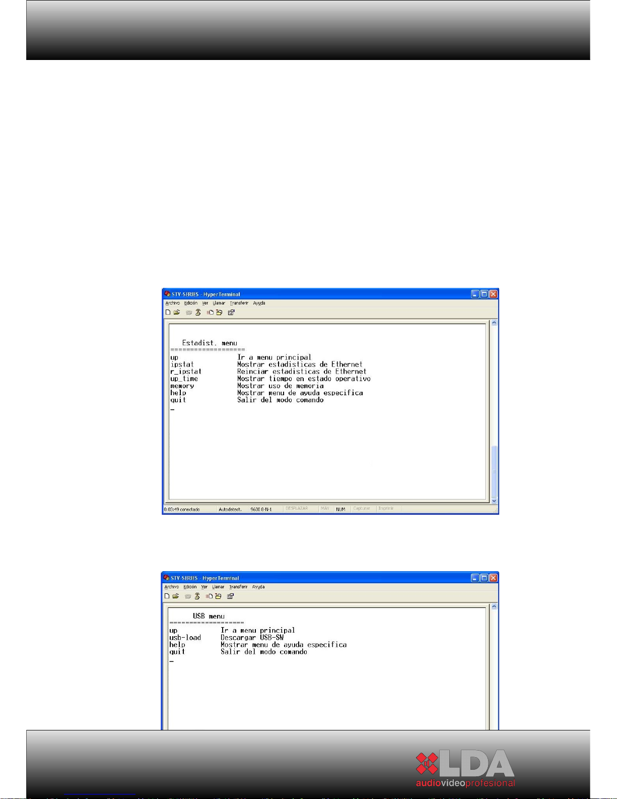
The main menu is compound for others submenus, where all the basic
adjustment functions can be realized. They are:
LAN SETTING:
Only available for the version including ETX-1/ETX-1CN
MANAGEMENT:
28
Page 29
STV SERIES
SUMMARY/ESTATISTICS:
Only available for the version including ETX-1/ETX-1CN
USB:
29
Page 30
USER MANUAL
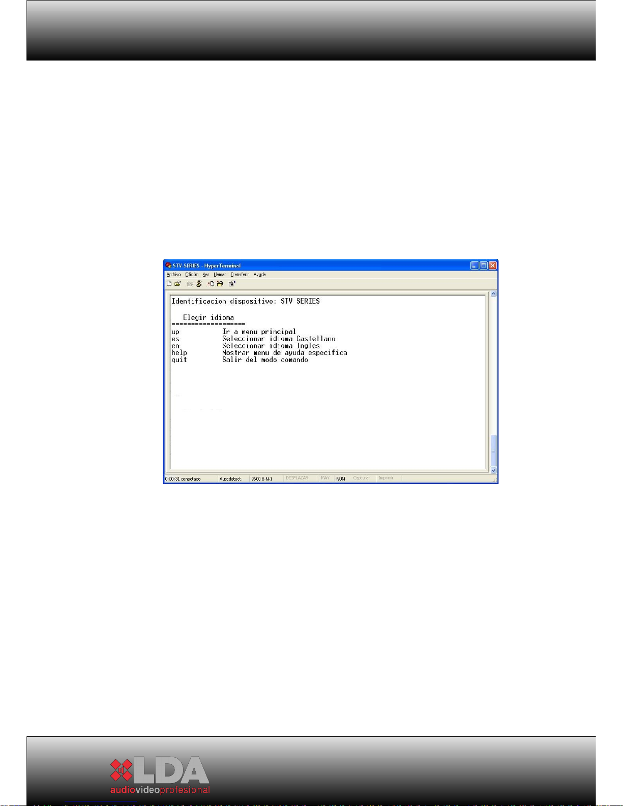
LANGUAGE:
The Help tool is shown in all the menus. The option "UP", which is used to return
up to the previous menu, is shown too.
All the settings by USB connection are updated in the equipment immediately. If
the language is modified trough out USB, the USB interface change to it at the
same time that the equipment display. It will be after the following Display
updating.
30
Page 31
STV SERIES
5 ETX SERIES MODULES:
5.1 TECHNICAL DESCRIPTION:
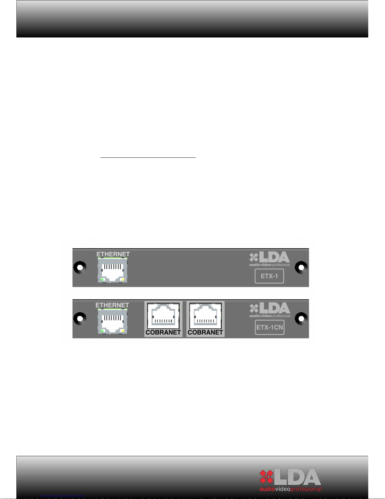
The expansion modules of the LDA ETX series allow the STV series to
enlarge their integration and connectivity features. Both modules are insertable,
exchangeable and easy to install in the system, thanks to a sole 40-wire ribbon
cable connector with polarity.
5.1.1
ETX-1 MODULE:
The ETX-1 module enables controlling and monitoring the STV series
monitors through Ethernet. All the functions of the amplifier, controlled with the
front panel menu, can be remotely operated.
When an amplifier of the STV series is controlled remotely, the local
controls (located both on the front panel and on the back) remain blocked.
If the remote control communication is established correctly, this will be
indicated by the “Link” LED on the amplifier’s front panel.
31
Page 32

USER MANUAL
The ETX-1 module can be configured from the equipment’s front panel
or remotely.
32
Page 33

STV SERIES
33
Page 34
USER MANUAL
5.1.2
ETX-1CN MODULE:
The ETX-1CN module includes all the features of the ETX-1 module. It
also allows fitting the STV series amplifiers with direct CobraNetTM inputs.
When an ETX-1CN module is connected to an STV amplifier, the
CobraNetTM audio inputs are selected as default inputs to the amplifier channels.
These audio inputs can be changed to analogue by means of remote
configuration.
The ETX-1CN module has two “COBRANET” inputs, a main one and a
reserve. When the first input (on the left) losses communication with the
network, for example because a switch has fallen, the ETX-1CN module will try
to connect through the second “COBRANET” input. This is useful to ensure
greater security in case of digital audio network redundancy.
The ETX-1CN module can be configured from the equipment’s front panel
or remotely.
34
Page 35
STV SERIES
5.2 INSTALLATION OF ETX MODULES:
To install the ETX series modules correctly, you must follow the following
steps:
1- Turn the STV amplifier off with the switch located on the back of the
device.
2- Pull out the two screws that secure the existing module. Keep the
screws.
3- Disconnect the ribbon wire of the existing module and leave it outside
the device.
4- Connect the ribbon wire to the ETX module. The connector to be
inserted is polarised.
5- Insert the new module, which is already connected, inside the
expansion bay.
6- Secure the module to the system with the screws that used to secure
the original module.
7 - Turn the equipment on. The appropriate start-up test will run.
35
Page 36

USER MANUAL
NOTE: The new module will be default installed with the same setting
than the previous module, except for the setting in ETX-1CN by
CobraNetTM.
36
Page 37
STV SERIES
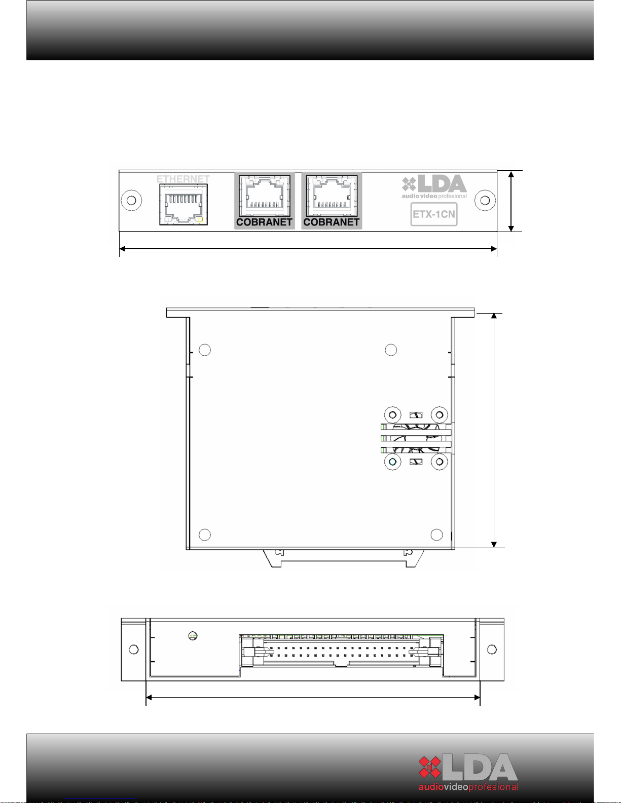
5.3 TECHNICAL SPECIFICATIONS:
FRONT PANEL VIEW:
TOP VIEW:
BACK VIEW:
37
21.5 mm.
131.8 mm.
115 mm.
103.5 mm.
103.5 mm.
Page 38
USER MANUAL
5.3.1
ETX-1 MODULE:
ETX-1
38
Page 39
STV SERIES
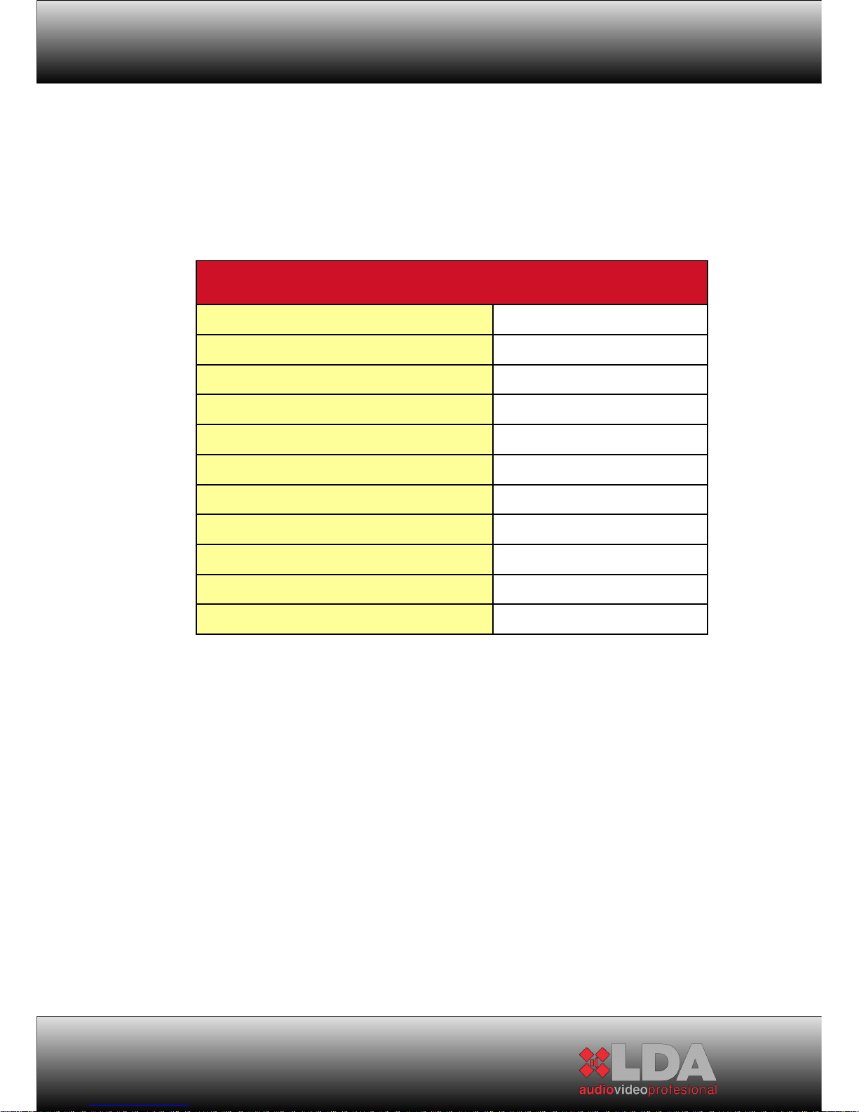
5.3.2
ETX-1CN MODULE:
The ETX-1CN module has all the features of model ETX1. It also includes
the following characteristics:
ETX-1CN
39
Page 40
USER MANUAL
6 TECHNICAL SPECIFICATIONS:
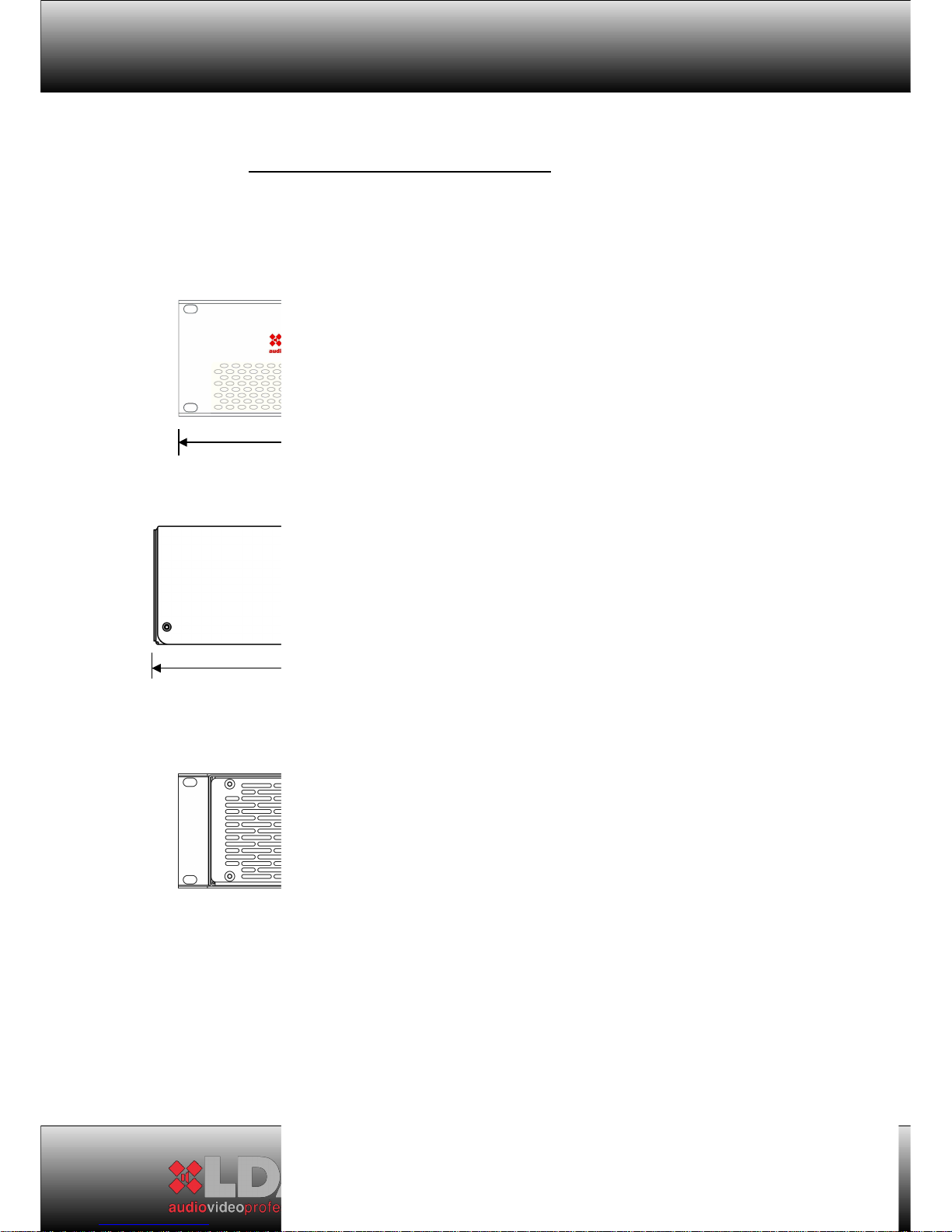
6.1 MECHANICAL CHARACTERISTICS:
FRONT VIEW:
SIDE VIEW:
BACK VIEW:
The views correspond to the 4-channel models without an expansion
module. The size of all models is the same.
40
483 mm.
455 mm.
88 mm.
Page 41
STV SERIES
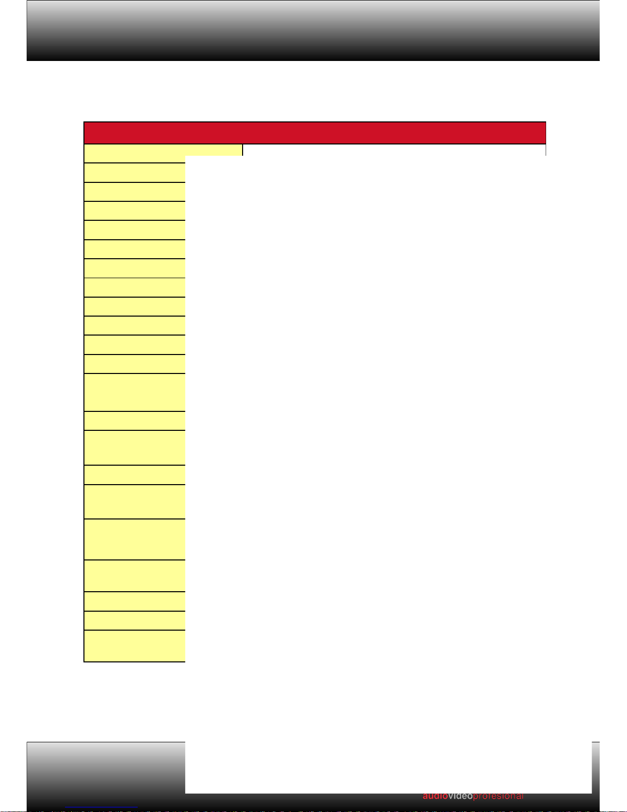
6.2 GENERAL SPECIFICATIONS:
41
Priority regenerated output
connector
Euroblock type of 4 removable contacts. Wire secured with screws
Priority regenerated output
impedance
100 (Balanced)Ω
Indicators On/Stand-By, Priori
ty, Link. Per channel: VU meter, signal, clip, state of
load, protection, display.
Control 128x64p graphic display and menu navigation controls. Gain
adjustment per channel from the front pannel or with potentiometer.
DSP Integrated. Controlled from the front panel. Optionally, controlled
remotely with ETX modules.
Dimensions 88 x 483 x 455 mm (height x width x depth).Two 19” rack units for all
Page 42

USER MANUAL
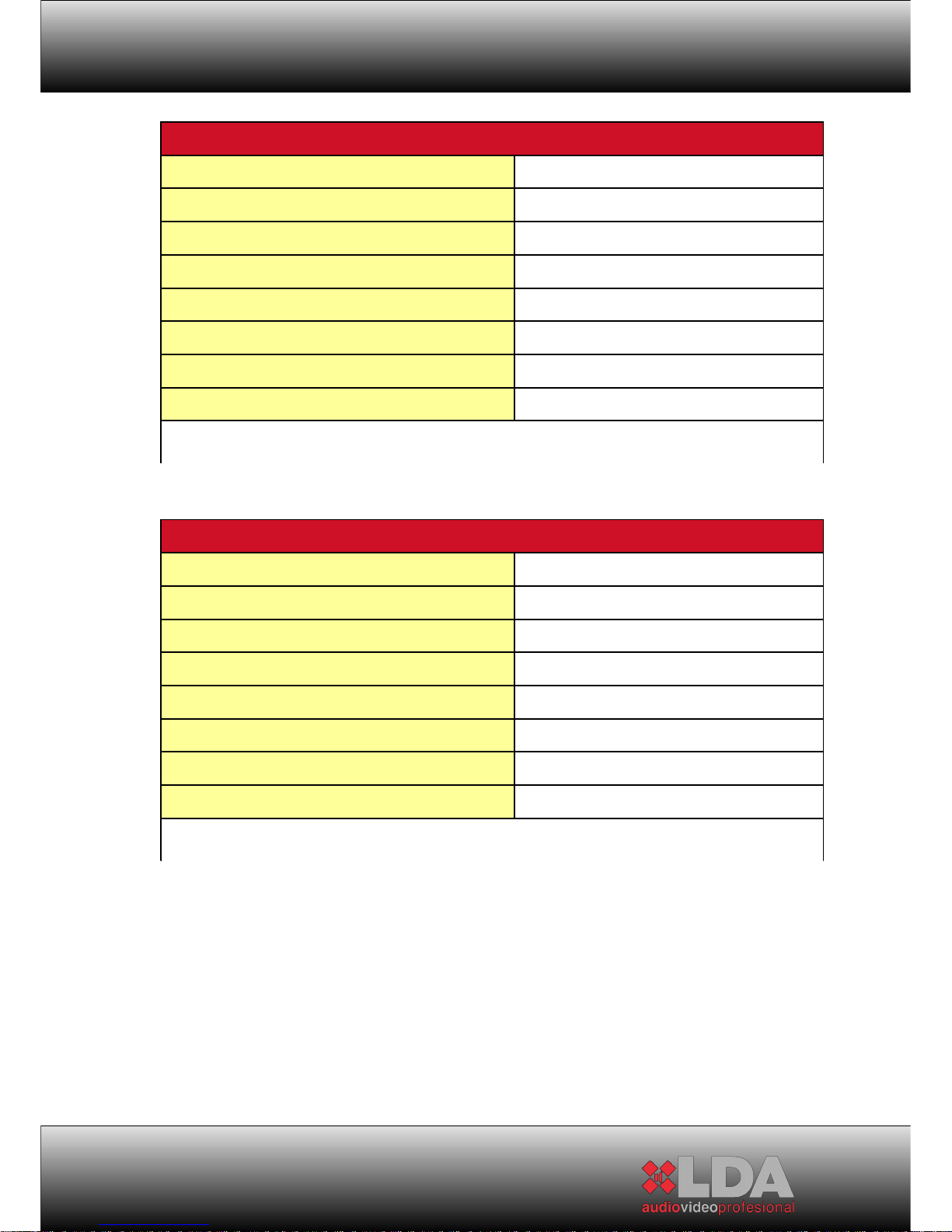
6.3 SPECIFICATIONS DEPENDING ON MODEL:
42
Page 43
STV SERIES
43
*SP= SPECIFIED POWER
Consumptions calculated with all channels active at 240V power supply.
*SP= SPECIFIED POWER
Consumptions calculated with all channels active at 240V power supply
Page 44
USER MANUAL
44
*SP= SPECIFIED POWER
Consumptions calculated with all channels active at 240V power supply.
*SP= SPECIFIED POWER
Consumptions calculated with all channels active at 240V power supply.
Page 45
STV SERIES
45
*SP= SPECIFIED POWER
Consumptions calculated with all channels active at 240V power supply.
Page 46
USER MANUAL
7 EQUIPMENT STATUS AND FAILURE MESSAGES
46
FAILURE DIAGNOSTICS DESCRIPTION SOLUCION
1041 ON/STBY lights
flashing green and
orange or red and
orange,
Indicators failure The front isn't supervised. The parmeters
shown belong to the previous valid status.
The parameters which are read by remote
way and the work of the equipment are not
modified by this case. Contact with S.A.T.
LDA.
1041 ON/STBY lights
flashing green and
orange or red and
orange.
The equipment can't
start-up.
Control module
failure
Make sure that ETX Control module is
connected correctly. Follow the described
steps in the previous section 4.2. If the
problems goes on, contact with LDA SAT.
ON/STBY lights in
permanent red. The
equipment can't startup. It is reset
automatically each 40
seconds and makes
three tries for startingup.
Start-up test If the Start-up test isn't passed, power
supply isn't working correctly or it can not be
supervised, turn the equipment off and
contact with LDA SAT.
STATUS lights flashing
orange.
Input module
failure
The control over the input module or the
channels isn't exist. It hold the previous
valid status. Contact with LDA SAT.
Page 47
FAILURE DIAGNOSTICS DESCRIPTION SOLUCION
STATUS lights in
permanent red.
Protected
amplifier channel.
The amplification channel is protected by
over-temperature or over-voltage. Turn the
equipment off, check the channel load is
contained between the recommended
parameters for the specified power. Check
the air flow grilles aren't locked. Wait some
minutes while the equipment temperature
decreases. Turn the equipment on. If the
equipment is protected again some minutes
before, contact with LDA SAT.
Page 48
USER MANUAL
8 AVERAGE TIME FOR REPAIRING , MTBF:
The event or average time for repairing curve shows that the failure
concentration is located at the beginning and at the end of this life-time curve.
For that reason, the average time for repairing could be calculated. This curve
could be modified due to changes in the environment, it is recommended to put
attention in the changes of external agents over the installation.
The same techniques and standards are used since the maximum level of
difficulty to the minimum level, it means to the last level of each components.
This complete study over the esteemed average time and life-time allows to
obtain a rate, which will be applied for the final product. The rate could be
calculated by different standardized equations for obtaining the esteemed lifetime, being this result modified to become in a real value. This real value is
conditioned by real working time of components and electrical and physics
stress under normal working.
The theoretical result is modified by real tests and corrections through out
a serious control of failures. All failures are controlled and registered for each
product in order to compare the precision of the calculated previsions. The
horizontal distribution allows to detect the failure in other equipments before the
failure appearance.
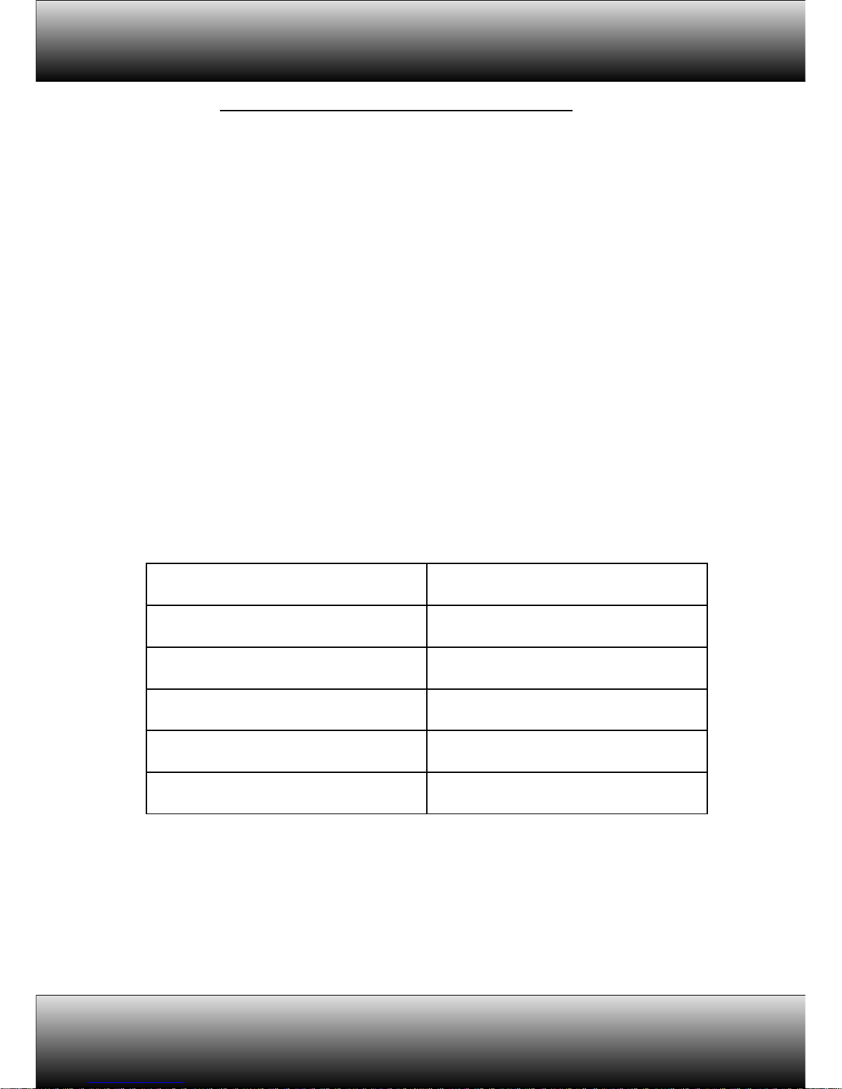
Next table stores different equipment models together with their
esteemed average time for repairing following the calculation described below:
CODE OF EQUIPMENT MTBF (years)
LDASTV2200S01 27,5
LDASTV4200S01 26,1
LDASTV2400S01 24,8
LDASTV4400S01 23,4
LDASTV2800S01 22,5
48
Page 49
STV SERIES
9 NOTES:
49
Page 50

USER MANUAL
50
Page 51

Address:
Parque Tecnológico de Andalucía
C/Severo Ochoa 31
CP:29590
Tel.: 952028805
Fax.952020598
©LDA 2010 All rights reserved. Revision 0.
www.lda.es
 Loading...