

Page 1

User's Manual
EN 54-16 certified PA/VA system LDA NEO
Page 2

SAFETY INSTRUCTIONS
Please read carefully these safety instructions.
1. Keep this User Manual for future reference.
2. Power connectors must stay accessible for disconnection and power cord must be placed
where people will not step or stumble. Unplug the equipment from the AC/DC before
cleaning.
3. The equipment must not be exposed to water and water containers must not be placed
over it. Do not use liquid or sprayed detergent for cleaning. Do not expose this equipment
to humid areas.
4. Do not place naked flames near the equipment.
5. Install this equipment in a safe surface. If the equipment is not in a safe surface, it may fall
and be damaged.
6. The openings on the enclosure are for air convection. Do not allow overheat. DO NOT
COVER THE OPENINGS. Leave at least 5cm of space at the sides for its correct
ventilation.
7. Never open the equipment. For safety reasons, the equipment should only be opened by
qualified personnel.
8. The equipment must be plugged into a grounded outlet.
9. Pay attention to connection polarity when operating the machine with a power supply (DC).
Reverse connection polarity may cause damage to the equipment, or to the power supply.
10. Let staff check the equipment if any of these situations occur:
a) The power cord or power plug is damaged.
b) Liquid has penetrated inside the equipment.
c) The equipment has been exposed to moisture.
d) The equipment does not work well or does not work according to the instruction
manual.
e) The equipment was dropped and damaged.
f) If the equipment has obvious signs of damage.
11. Cabling must be done only by trained personnel. Disconnect the audio inputs and outputs
while making connections or disconnect the equipment from the power supply. Be sure to
use the proper cables to make the connections.
Page 3

Index
1 INTRODUCTION............................................................................................................................ 1
2 DESCRIPTION............................................................................................................................... 2
2.1 INDICATORS.................................................................................................................................2
2.1.1 GENERAL STATUS INDICATORS ............................................................................................... 2
2.1.2 CHANNEL STATUS INDICATORS................................................................................................ 2
2.1.3 SUPERVISED FUNCTION INDICATORS...................................................................................... 3
2.1.4 EMERGENCY SOURCES INCDICATORS.................................................................................... 3
2.2 CONTROLS................................................................................................................................... 4
2.2.1 DIRECT ACCESS CONTROLS...................................................................................................... 4
2.2.2 SCROLL BUTTONS....................................................................................................................... 4
2.2.3 TEST............................................................................................................................................... 4
2.2.4 RESET/ RST................................................................................................................................... 4
2.2.5 ACK................................................................................................................................................. 5
2.2.6 CONTROL WINDOW...................................................................................................................... 5
2.2.7 ZONE SELECTION WINDOW....................................................................................................... 5
2.3 USER PROFILES - ACCESS LEVEL. PASSCODE.................................................................... 7
2.3.1 ACCESS LEVEL 1 ......................................................................................................................... 7
2.3.2 ACCESS LEVEL 2.......................................................................................................................... 7
2.3.3 ACCESS LEVEL 3.......................................................................................................................... 7
2.4 INPUTS Y OUTPUTS.....................................................................................................................8
2.4.1 EMERGENCY POWER SUPPLY MONITORING......................................................................... 8
2.4.2 EMERGENCY ACTIVATION INTERFACE.................................................................................... 9
2.4.3 SPEAKER LINE DEVICES INTERFACE..................................................................................... 10
2.4.4 EXTERNAL SYSTEMS SLOT INTERFACE................................................................................. 11
2.4.5 POWER SUPPLY......................................................................................................................... 14
2.4.6 SPEAKERS LINES....................................................................................................................... 15
2.4.7 INPUTS AND OUTPUTS OF AUDIO SOURCES........................................................................ 16
2.4.8 SYSTEM INTEGRATION PORTS................................................................................................ 17
3 FUNCTIONING............................................................................................................................ 19
3.1 SYSTEM BOOTING.....................................................................................................................19
3.2 EMERGENCY.............................................................................................................................. 19
3.2.1 ACTIVATING THE EMERGENCY STATE................................................................................... 19
3.2.2 ACTIVATING THE VOICE ALARM.............................................................................................. 19
3.2.3 STOPPING VOICE ALARM.......................................................................................................... 20
3.2.4 DEACTIVATING THE EMERGENCY STATE.............................................................................. 20
3.2.5 EMERGENCY STATE LOG......................................................................................................... 20
3.2.1 VOICE EVACUATION ZONE VOLUME ADJUSTMENT ........................................................... 20
3.3 FAILURE......................................................................................................................................21
3.3.1 FAILURE STATE LOG................................................................................................................. 21
3.3.1 RESET FAILURE'S STATE.......................................................................................................... 21
3.4 DESARMING................................................................................................................................21
3.4.1 DEACTIVATING/ ACTIVATING A ZONE..................................................................................... 21
3.4.2 DISARM LOG............................................................................................................................... 21
3.5 PA MODE.....................................................................................................................................21
3.5.1 ZONE VOLUME SETTING........................................................................................................... 22
3.5.2 ROUTE SOURCES....................................................................................................................... 23
3.5.3 AVANCED OPTIONS................................................................................................................... 24
3.5.4 AVANCED OPTIONS. AUDIO INPUT.......................................................................................... 25
3.5.5 AVANCED OPTIONS. AUDIO OUTPUT...................................................................................... 26
3.5.6 AVANCED OPTIONS. MONITOR................................................................................................ 27
3.5.1 AVANCED OPTIONS. MESSAGES............................................................................................. 28
3.5.1 ADVANCED OPTIONS. LOAD PRESET..................................................................................... 29
3.5.2 ADVANCED OPTIONS. SYSTEM ............................................................................................... 29
4 CONNNECTION AND SETUP..................................................................................................... 32
4.1 EMERGENCY SUPPLY SYSTEM...............................................................................................32
4.2 PAGING MICROPHONES AND PA ELEMENTS (ACSI BUS)...................................................33
4.3 FLEXNET CONNECTION ...........................................................................................................33
4.4 VOICE EVACUATION ZONES....................................................................................................34
4.5 BACK-UP AMPLIFICATION .......................................................................................................34
4.6 SPEAKER LINES.........................................................................................................................35
4.6.1 LINE CABLING. STANDARD MODE........................................................................................... 35
4.6.2 LINE CABLING. AB MODE.......................................................................................................... 35
4.6.3 SUPERVISION OF SPEAKER CONNECTIONS......................................................................... 36
4.6.4 END OF LINE DEVICES.............................................................................................................. 36
4.7 VOLUME CONTROLLERS..........................................................................................................39
5 FAILURE DETECTION................................................................................................................ 40
5.1 SPEAKERS LINE.........................................................................................................................40
5.2 TRANSMISSION LINE WITH CIE............................................................................................... 40
Page 4

5.3 PROTECTION DEVICES ............................................................................................................40
5.4 POWER SUPPLY ........................................................................................................................40
5.5 LINK.............................................................................................................................................40
5.6 SYSTEM.......................................................................................................................................41
6 MAINTENANCE INSTRUCTIONS .............................................................................................. 42
7 TECHNICAL FEATURES............................................................................................................ 43
8 Appendix A: EN 54-16 features................................................................................................. 46
9 Appendix B: LOG Content......................................................................................................... 48
9.1 STATE OF EMERGENCY LOG...................................................................................................48
9.2 STATE OF FAILURE LOG..........................................................................................................48
9.3 STATE OF DISARMED LOG.......................................................................................................48
10 Appendix C: Cabling section for speaker lines..................................................................... 49
Page 5

1 INTRODUCTION
The PA/VA system LDA NEO is certified according to EN 54-16, ensuring a safe and
controlled emergency evacuation. Its high performance, versatility and audio quality make it
also a powerful and cost-effective background music and paging system for all types of
facilities.
This document is valid for the following equipment of the NEO series:
• NEO8060. Main system controller. Includes all the main functions required for the PA/VA
system. Includes 8 amplifiers/zones of 120W.
• NEO8250E. System Extension that includes 8 amplifiers/zones of 250W.
• NEO4250E. System Extension that includes 4 amplifiers/zones of 250W.
• NEO4500E. System Extension that includes 4 amplifiers/zones of 500W.
• NEO4500LE. System Extension that includes 4 amplifiers/zones of 500W for low
impedance speaker lines (8 and 4 Ohms)
NOTE: This document has been revised for the Firmware version v2.25.xx.28.
Other equipment referenced in this document are:
• LDANEOTFL. End-of-line (EOL) device.
• LDAMPS-8Z. Expandable 8-zone microphone.
• LDAVAP-1. Fireman panel with optional zone selection.
LDA Audio Tech - Severo Ochoa Nº 31- 29590 MÁLAGA, ESPAÑA. Tlf: +34 952028805
1
User's Manual: EN 54-16 PA/VA System LDA NEO
Page 6

2 DESCRIPTION
The main controller of the PA/VA system manages all the audio inputs of the system, either
conventional or emergency inputs, and routes them to the existing zones. The controller NEO,
follows all the requirements in accordance with EN 54-16 and EN 60849 normatives.
In order to scale the system there are different NEO-Extension models that can be connected
to the main controller by redundant Ethernet connection. They expand the system in number of
zones, amplifier channels and available lines including all the necessary functions, being
certified elements of the EN 54-16 system.
2.1 INDICATORS
2.1.1 GENERAL STATUS INDICATORS
Status indicators show at all times the operating condition of the equipment or system.
They are located at the left of the screen.
a) POWER: “POWER”. Green
Active (on) when the unit is powered from any of the power supply sources.
b) EMG: “EMERGENCY”. Red
Active (on) when the equipment is in a state of emergency operation (voice alarm) by
manual activation or automatic activation from the CIE, at any of the voice alarm zones.
Simultaneously once the indicator is switched on, it will emit a continuous audible
warning . This warning can be silenced by pressing the touch-button "ACK" (Acknowledge), or
automatically when using the emergency microphone.
c) FLT: “FAULT”. Amber
Active (on) when the equipment is in a fault state. This indicator is activated
automatically upon detection of failure of any supervised functions.
Simultaneously, the LED indicator and an audible warning will be issued intermittently.
This warning can be silenced by pressing the touch-button "ACK", or automatically when using
the emergency microphone.
d) DIS: “DISARMED” / “DESACTIVADO”. Amber
Active (on) when any zone from the voice alarm zones is disabled.
e) PA: “PUBLIC ADDRESS”. White
Active when the equipment is not in a state of emergency.
2.1.2 CHANNEL STATUS INDICATORS
The channel status indicators show at all times the channel operating state or condition.
2
www.lda-audiotech.com
Picture 1: Indicators
User's Manual: EN 54-16 PA/VA System LDA NEO
Page 7

(f) EMG: “EMERGENCY” . Red
Active (on) when the equipment is in a state of emergency operation (voice alarm) or by
manual or automatic activation from the CIE, of any of the voice alarm zones. When the
system is in a state of emergency and it is broadcasting a spoken voice, either through the
emergency microphone or by a prerecorded evacuation message, the indicator light will flash.
(g) FLT/DIS: “FAULT / DISARMED” . Amber
Active (on) when the voice evacuation channel is turned off.
Active (flashing) when a fault is detected on a voice evacuation channel. This indicator
is activated automatically upon detection of failure of any supervised functions in the channel.
If none of the indicators of general supervised function is on, it will indicate a fault in the
speaker's line. Restart the fault condition.
(h) SIGNAL: “SIGNAL”. Green
Active (on) when it detects an amplifier channel output signal from the corresponding
voice evacuation zone. The minimum level at which the indicator lights is -50dB.
2.1.3 SUPERVISED FUNCTION INDICATORS
Supervised Functions indicators show the faults that affect the general system
functions.
i) CIE: “CIE” / “ECI”
Active (on) when a failure occurs in the transmission line between the CIE and the
system. Reset fault condition. If fault the persists, see chapter 5.2 for its resolution. Amber
colour.
j) PROTECT: “PROTECTION”
Active (on) when any of the system protection devices are active. Restart the fault
condition. Reset fault condition. If the fault persists, see chapter 5.3 for its resolution. Amber
colour.
k) POWER: “POWER” / “ALIMENTACIÓN”
Active (on) when there is a power failure in the system. It may be due to a failure at the
main power supply or at the emergency power supply. Reset fault condition. If the fault
persists, see chapter 5.4 for its resolution. Amber colour.
l) LINK: “LINK” / “ENLACE”
Active (on) when there is a link failure between the equipment, and some elements of
the distributed system. Reset fault condition. If the fault persists, see chapter 5.5 for its
resolution. Amber colour.
m) SYSTEM: “SYSTEM” / “SISTEMA”
Active (on) when there is a failure in the execution of the equipment's software, or in its
memory. Reset fault condition. If the fault persists, see chapter 5.6 for its resolution. Amber
colour.
2.1.4 EMERGENCY SOURCES INCDICATORS
Emergency sources indicators indicate the operating status of prerecorded messages,
and the emergency microphone.
(n) EVAC: “EVACUATION”
Active (on) when the evacuation message is being broadcast in the selected voice
alarm zone. Red colour.
(o) ALERT: “ALERT”
Active (on) when the alert message is being broadcasted in the selected voice alarm
zone. Amber colour.
LDA Audio Tech - Severo Ochoa Nº 31- 29590 MÁLAGA, ESPAÑA. Tlf: +34 952028805
3
User's Manual: EN 54-16 PA/VA System LDA NEO
Page 8

(p) EMIC: “EMERGENCY MICROPHONE”
Active (on) when the microphone is available to perform an emergency evacuation in
the selected zones. If the indicator is off, wait for it to be turned on, a warning sound signal
might be played. Amber colour.
2.2 CONTROLS
2.2.1 DIRECT ACCESS CONTROLS
These controls are located on the left side of the screen. They allow direct access to
the notification windows of the active states. They show extended information about operating
status and available options.
a) EMG: “EMERGENCY”
It allows access to emergency status menu. When the equipment or system is in this
state, you will enter directly to the window with extended information about the state of
emergency. To continue operating the equipment, press the " BACK" button.
b) FLT: “FAULT”
It allows access to the window of extended information about the fault state. Faults are
displayed while the fault is not restarted, and up to 5 minutes after a reboot had occurred.
c) DIS: “DISARMED”
Accesses the disarmed menu . If there is a disabled zone, it will go directly to the
window with extended information about the disable state.
d) PA / BACK: “PA/BACK”
It allows access to the PA menu when the equipment is not in a state of emergency, or
failure.
It also allows the go-back function for navigation through the menus . The button " PA " will
change to "BACK" button when the option is available again.
2.2.2 SCROLL BUTTONS
The scroll buttons are situated to the right side of the screen. They allow a scroll up /
down within the windows displayed on the screen. It includes the "OK " button for operations
that require confirmation.
2.2.3 TEST
The "TEST" button is located under the direct access controls. It allows to check the
correct functioning of all indicators of the equipment. While the "TEST" button is being pressed
it will turn on simultaneously , all the indicators, and an audible warning will be emitted. The
screen will go into test mode. Once the button is released, the test will end. During the testing
process all manual controls will be inactive. If they receive a signal from the CIE, for the
activation of an emergency warning, the test will end.
2.2.4 RESET/ RST
The "RESET" button is located on the top right side of the screen. The "RESET" button
resets the operating condition of the equipment when it is in a state of emergency or fault.
NOTE: If pushed twice in an interval of time less than 10 seconds, it will perform a
software reset of the control module of NEO and its extensions. This action stops the
execution of events, stops the microphones, playback of pre-recorded messages, etc.
4
www.lda-audiotech.com
Picture 2: Controls
User's Manual: EN 54-16 PA/VA System LDA NEO
Page 9

2.2.5 ACK
The button " ACK " is situated under the button "RESET " on the right side of the
screen. I allows the confirmation that the emergency mode or fault status indication has been
acknowledged. By pressing it, the emergency or fault audible beep will be muted.
2.2.6 CONTROL WINDOW
The following describes the
information that, continuously, can be
viewed in the control window.
(a) NAVIGATION LEVEL
In the upper right side there is
the menu level indicator in which the
user is located. As we examine the
menu it displays a higher level.
(b) TITLE
On the top of the window, it
indicates the title of the section in
which the user is operating.
(c) ACCESS LEVEL
Located in the upper right corner of the screen, it indicates the current access level
(see 2.3).
(d) WORKING AREA
The central area of the screen will show the information or controls that are available to
the user.
(e) LEFT BAR
Indicated by different colors, and along with the title , the menu in which the user is
working . For emergency is red and for fault or disarmed zones is yellow.
(f) SCROLL BAR
At some windows this item may appear. It indicates that there are more objects to be
displayed in the same window upwards or downwards. To access them, use the scroll buttons
(see 3.2.2.).
The scroll bar can have three positions, top, middle or bottom, indicating, beginning,
middle and end area respectively.
(g) HELP / ACTION
In the lower area of each window there is a help text indicating the next step to be
performed by the user.
2.2.7 ZONE SELECTION WINDOW
In the zone selection window, over
the zone/zones to make a selection. If you
click on a selected zone, it will be
deselected. When the zone is selected, the
button will show a band. There may be
zones that are not displayed on screen, to
scroll through the zone selection window,
use the scroll controls, located at the right
side of the screen. On the right side of the
window, the scroll bar indicates the current
position in the window (see 2.2.6).
LDA Audio Tech - Severo Ochoa Nº 31- 29590 MÁLAGA, ESPAÑA. Tlf: +34 952028805
5
Picture 4: Zone selection window
User's Manual: EN 54-16 PA/VA System LDA NEO
Picture 3: Control window
Page 10

Once the selection has been made, press the "OK" control to confirm navigation,
pressing the "BACK" button, the selection will be cleared. If you did not select any zone, and
press "OK", and the equipment / system will perform an automatic selection of all zones.
In each zone depicted on screen, it is indicated the state of the zone. It will be identified
as follows:
(a) ZONE IN STATE OF EMERGENCY
Red box on the left side of the zone button. In Picture 4, zone 1
(b) SELECTED ZONE
Selection band in the right side. In Picture 4, zones 1, 2, 3, 4 and 7
(c) ZONE INDICATING FAULT
Yellow rectangle on the left side of the zone button. In Picture 4 zone 4
(d) ZONA NO SELECCIONADA
No selection band. In Picture 4, zones 5 and 6. Zone 8 can not be selected by default once
disarmed (see 3.4).
(e) DISARMED ZONE
Disabled zone. Yellow band on the right side. The button will be a dark-colored area in Picture
4 zone 8
6
www.lda-audiotech.com
User's Manual: EN 54-16 PA/VA System LDA NEO
Page 11

2.3 USER PROFILES - ACCESS LEVEL. PASSCODE
The access levels define the different user profiles that can operate the equipment /
system. Each of the access levels, provides permissions to different menu items, level 1
having the lowest, and level 3 the highest number of options available.
To access a specific level of access, you must perform access control satisfactorily.
Once done, you can navigate the options, until you return to the home screen, or do not
perform any operation for more than 90 seconds.
The way to perform access control can be set in each of the levels. It is possible to
choose from confirmation mode, or access via 4-digit passcode with the configuration
application.
2.3.1 ACCESS LEVEL 1
The access level 1 corresponds to the general user profile, or people who have a
general responsibility for security supervision, which may initially respond to an emergency
status, or failure.
2.3.2 ACCESS LEVEL 2
The access level 2 corresponds to a security manager profile who has specific training
to operate the equipment / system in the states of "PA", "Emergency", "Failure message" and
"Disarmed".
2.3.3 ACCESS LEVEL 3
The access level 3 corresponds to the administrator profile, who has specific training to
modify the system configuration and perform the maintenance, according to the instructions
and information presented in this manual.
LDA Audio Tech - Severo Ochoa Nº 31- 29590 MÁLAGA, ESPAÑA. Tlf: +34 952028805
7
Picture 5: Types of Control Access Windows
User's Manual: EN 54-16 PA/VA System LDA NEO
Page 12
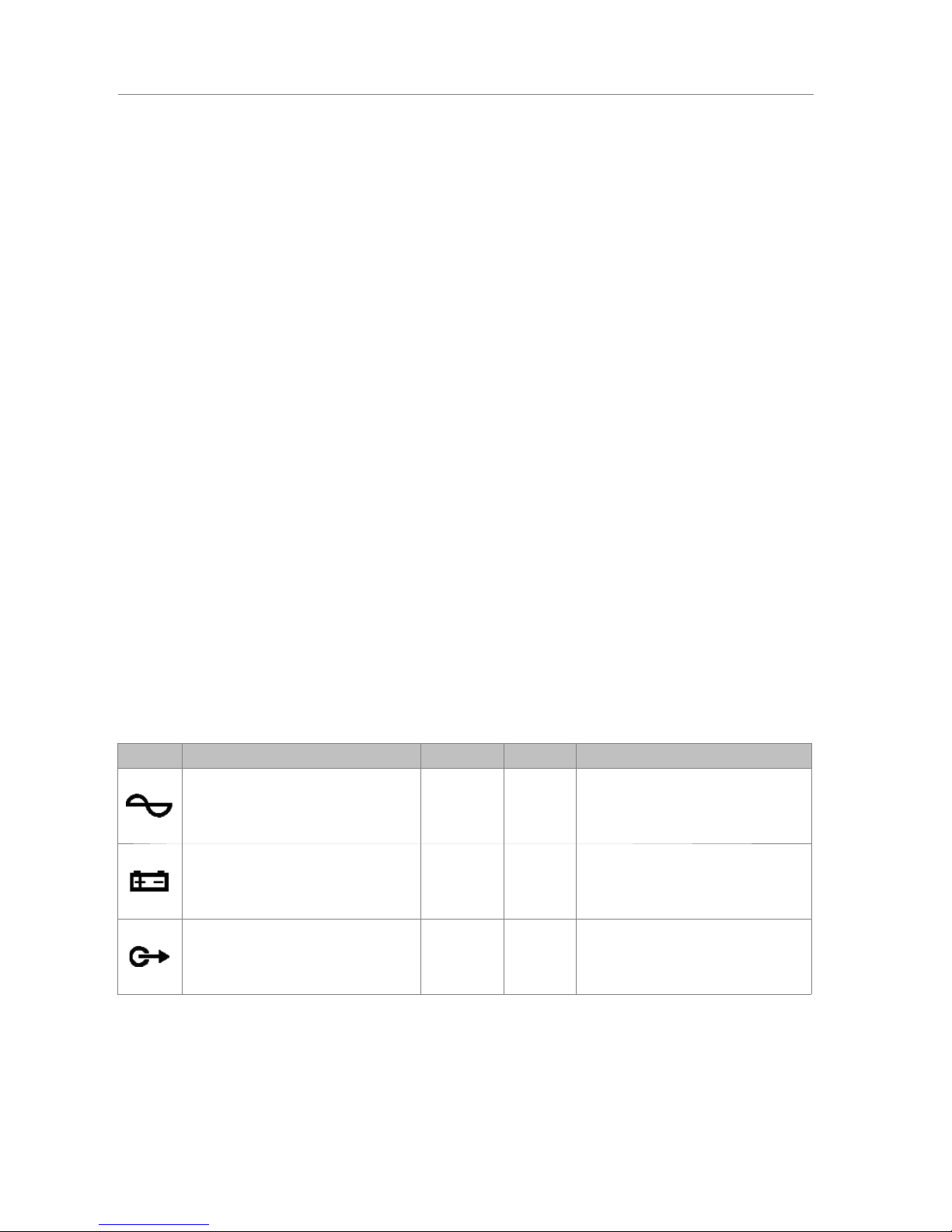
2.4 INPUTS Y OUTPUTS
In this chapter are described the rear connectors of the NEO series equipment.
Depending on the model, the equipment will or will not include some of the types described in
this section and quantity may vary.
The monitoring interfaces for emergency power supply and general inputs/outputs for
activating the emergency, are available in all equipment of the NEO series. From the
configuration software it is possible to select which ones will be used.
2.4.1 EMERGENCY POWER SUPPLY MONITORING
(a) MONITORING INPUTS FOR THE EMERGENCY POWER SUPPLY
It allows the connection to the system of the statusoutput signals from the emergency back-up power supply.
It has three double contact closure inputs: main power
supply failure, battery failure, failure in any of the
emergency power outputs.
Each input has three terminals: Normally Closed
(NC), Common and Normally Open (NO). To activate any
of the fault signals, a contact closure input on NO should be produced, and simultaneously an
opening of a contact closure on NC input. In any other case, it will detect fault in the
connection.
The connection is made through a female 9 pin euroblock connector and 3.81 mm pitch
(supplied with the unit). The wire size range for each pole of this connector is: 0.14 1.5 mm2
(30 14 AWG).
Marking Description Type Signals Activation
Failure in the main power supply. Input NC ┴ NO
Contact closure free of voltage between
┴ NO
and
Open contact closure free of voltage
between ┴ NC
Battery failure Input NC ┴ NO
Contact closure free of voltage between
┴ NO
and
Open contact closure free of voltage
between ┴ NC
Failure in the emergency power
supply output. Input NC ┴ NO
Contact closure free of voltage between
┴ NO
and
Open contact closure free of voltage
between ┴ NC
Table 1: Emergency Source Monitor Inputs
NOTE: Some EN 54-4 battery chargers have the same monitoring interface but with the
inverse meaning of the NC and NO. It is recommended to revise the operating instructions in
the user's manual. E.g. The model SONAES requires to invert the NC and NO connections.
8
www.lda-audiotech.com
Picture 7: Monitoring inputs for the back-
up power supply.
User's Manual: EN 54-16 PA/VA System LDA NEO
Picture 6: Inputs and Outputs
Page 13

2.4.2 EMERGENCY ACTIVATION INTERFACE
The emergency activation interface is indicated to perform an interconnection with a fire
control and indication equipment (CIE). All input connections are supervised in order to detect
fault in the transmission line. This interface has three sections:
(a) GENERAL EMERGENCY MODE ACTIVATION INPUT
It allows activation and deactivation of the emergency mode of the entire system. It
consists of two supervised inputs for the connection of voltage-free contact closures: Reset
and Emergency. In order to have the link monitored, the contact closure connections to the
equipment shall be done by two 10k external electrical resistances (supplied with the unit),
placed at the output of the CIE as shown in the Picture 9.
When the emergency input (EMG) is on, the machine will automatically switch from PA
mode, to a state of emergency, and it will broadcast the voice evacuation message at all zones
of the system (default option). The default evacuation sequence can be configured through the
configuration software. When the reset input (RST) is enabled, the
system will exit the emergency mode and return to the normal state.
If an error occurs in the transmission line between the CIE and the
equipment, it will produce a fault indication in the front panel. (see
2.1.3). In systems in which these inputs are not used, connection
monitoring must be disabled in the configuration software.
NOTE: For avoiding an unwanted activation, the system does
not allow that the activation inputs perform the sequence EMG, RST, EMG instantly. The
second consecutive activation will leave a time lapse of 5 seconds.
The connection is via a 4-pin female euroblock connector of 3.81 mm pitch (supplied
with the unit). The wire size range for each pole of this connector is: 0.14 1.5 mm2 (30 14
AWG).
Marking Description Type Signals Activation
RST
Input for Reset of the Emegency
State Input
┴ +
Voltage-free contact closure
between ┴ +
Supervised input
(see Picture 9)
EMG
Emergency State activation input
Input
┴ +
Voltage-free contact closure
between ┴ +
Supervised input
(see Picture 9)
Table 2: General Emergency Inputs
LDA Audio Tech - Severo Ochoa Nº 31- 29590 MÁLAGA, ESPAÑA. Tlf: +34 952028805
9
Picture 8: Emergency Activation Interface
Picture 9: Supervised connection with the CIE
Picture 10: General
Emergency
Activation Input
User's Manual: EN 54-16 PA/VA System LDA NEO
Page 14
(b) SUPERVISED STATUS OUTPUTS
The equipment has two output signals, which indicate the
operating state of the system. The EMG signal indicates that the system is
operating in emergency mode. FLT signal indicates that the system is in
failure mode. They consist of two voltage-free contact closure outputs
normally open (NO).
The connection is via a 4-pin female euroblock connector and 3.81 mm
pitch (supplied with the unit). The wire size range for each pole of this
connector is: 0.14 1.5 mm2 (30 14 AWG).
Marking Description Type Signals Activation
EMG Active Emergency State Output Output Close
Voltage-free contact closure
between terminals
(max 350mA / 350V dc)
FLT
Active Failure State Output
Active Disarmed State Output
Output Close
Voltage-free contact closure
between terminals
(max 350mA / 350V dc)
Fault: intermittent
Disarmed: Continuous
Table 3: System status outputs
(c) EMERGENCY-ZONE ACTIVATION INTPUT
It allows the configuration of eight sequences of evacuation defined by the user. By
default, each emergency activation input will activate the emergency in one zone. It has eight
supervised free voltage contact closure inputs. In order to have the link monitored, the contact
closure connections to the equipment shall be done by two 10k external electrical
resistances (supplied with the unit), placed at the output of the CIE as shown in Picture 9.
The manual activation has a higher priority over the
external activation inputs, hence the emergency state can be
stopped manually. The manual activation can not be stopped
from a remote input.
The connection is via two 8-pin female euroblock
connector of 3.81 mm pitch (supplied with the unit). The wire size
range for each pole of this connector is: 0.14 1.5 mm2 (30
14 AWG).
Marking Description Type Signals Activation
Zx
Activation of the Emergency State
Input in the Zone X Input
┴ +
Voltage-free contact closure
between ┴ +
Supervised Input
(see Picture 9)
Table 4: Emergency-zone activation inputs
2.4.3 SPEAKER LINE DEVICES INTERFACE
a ) ATTENUATORS OVERRIDE OUTPUT
The equipment has 8 outputs for overriding attenuators in the
PA line. At rest state they have 0V voltage. At active state, each
output, has a voltage of 24V dc (*) and 40mA of maximum electrical
current. Each output has 2 poles.
The connection is via two 8-pin female euroblock connector of
3.81 mm pitch (supplied with the unit). The wire size range for each
pole of this connector is: 0.14 1.5 mm2 (30 14 AWG).
10
www.lda-audiotech.com
Picture 11: System
Status Outputs.
Picture 12: Emergency-
Zone activation inputs
Picture 13: Attenuators
override outputs.
User's Manual: EN 54-16 PA/VA System LDA NEO
Page 15
Marking Description Type Signals Activation
OV-x Attenuation of attenuators output Output
+ -
24V dc 40mA
Table 5: Attenuators override outputs
NOTE: The average consumption of the attenuator override signal is 10mA per unit.
(*): The output voltage could vary between 20 and 27V depending on the state of the battery.
(b) END OF LINE INPUTS
The equipment has 8 dual inputs for connecting
end-of-line devices. Each input has 3 terminals, one
common and two terminals for lines A and B,
associated with the same amplifier channel (CH-x).
When the activation signal occurs at one of the inputs,
a loudspeaker line failure will be detected.
The connection is via 8-pin female euroblock
connector with 3 contact of 3.81 mm pitch (supplied
with the unit). The wire size range for each pole of this
connector is: 0.14 1.5 mm2 (30 14 AWG).
Marking Description Type sSignal Activation
CH-x End-of-line device input Input
┴ A B
Voltage-free contact closure ┴ A
Voltage-free contact closure ┴ B
Table 6:EOL device inputs
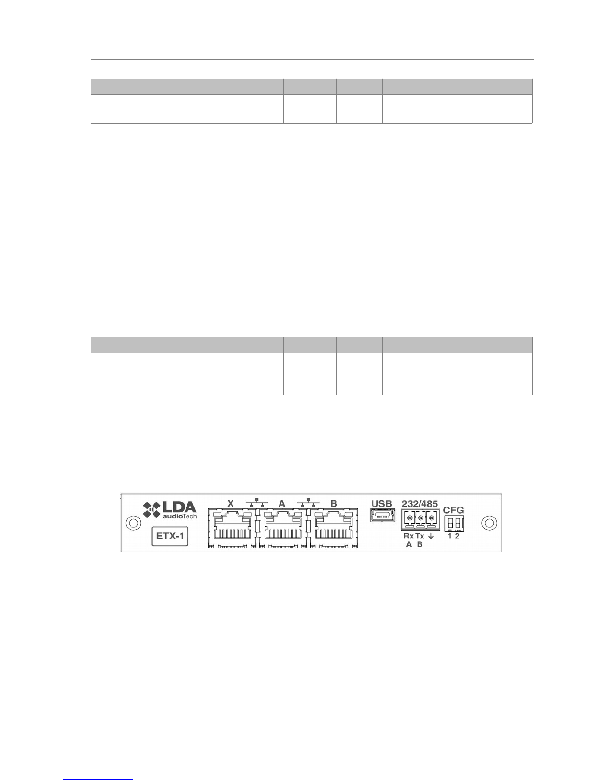
2.4.4 EXTERNAL SYSTEMS SLOT INTERFACE
The equipment has a slot where the ETX-1 module can be integrated. This module
allows connection to NEO-Extension units, the control, monitoring and configuration through
the data network, the reception of audio sources from the data network and the integration with
third-party systems. The ETX-1 module is delivered as part of the equipment.
(a) SYSTEM CONNECTION PORT X
The X port allows the connection of an external Ethernet network that can be used for
control, monitoring and configuration and the reception of audio over the data network. It is
possible to configure this port to be disabled during emergency mode, therefore enhancing the
security in the internal network.
(b) SYSTEM CONNECTION PORTS A AND B
The equipment has two ports for the connection with other systems and NEOExtension units. The behavior of this ports can be configured by a dip-switch as indicated in
section (e). The default mode will be position 01, where A will be the main Flexnet connection
and B the redundant Flexnet connection. In case of failure in port A, the system will
automatically switch to port B.
LDA Audio Tech - Severo Ochoa Nº 31- 29590 MÁLAGA, ESPAÑA. Tlf: +34 952028805
11
Picture 14: EOL device inputs
Picture 15: External Systems Slot Interface
User's Manual: EN 54-16 PA/VA System LDA NEO
Page 16

The connection is made using standard CAT 5 Ethernet network cable RJ-45 T568B
(the connection cable is supplied with the equipment).
MarkingDescription Type Signals Activation
X/A/B Ports for system connection Port
Ethernet
CAT5
Flexnet (propriety protocol)
UDP
Cobranet
Table 7: System connection ports
(c) USB PORT (reserved)
The USB port (mini USB type AB) integrated in the equipment
is reserved.
(d) INTEGRATION SERIAL PORT
The equipment has a two-wire RS-485 serial port.
The default configuration for events for integration with third
party systems is: 19200bps, 8 bits, even party bit, 1 stop bit.
The commands admitted in this port can trigger events in
the system that can be configured through the configuration
application.
NOTE: If configured for use of LDA VCC units, this port
could not be used for other devices.
The connection is made using a 3-pin female euroblock connector and pitch 3.81 mm
(supplied with the unit). The wire size range for each pole of this connector is: 0.14 1.5 mm2
(30 14 AWG). It is recommended to use twisted pair cabling for the connection of serial
signals.
Marking Description Type Signals Activation
485-AB
Terminal A and B, Serial
connection port for RS-485
integration
Port AB
Standard RS-485/9600/8/N/1
see configuration software.
485 ┴
Cable net drape NA NA NA
Table 7: Integration serial port
NOTE: The 232 marking corresponds to a reserved future use.
(e) SYSTEM CONNECTION CONFIGURATION SWITCH
The equipment has a dip-switch for configuring the behavior of the system connection
ports. Depending on the position according to the following table
12
www.lda-audiotech.com
Picture 17: Integration Serial Port
User's Manual: EN 54-16 PA/VA System LDA NEO
Picture 16: USB Port
Page 17

Marking Description Type Signals Activation
CFG
Port A : Control data exclusively
Puert B : Audio data exclusively
Puert X : Flexnet**
Config. NA Posición 00
CFG
Puert A : Flexnet**
Puert B : Flexnet**
Puert X : Control data exclusively
Config. NA Posición 01
CFG
Puert A : Flexnet**
Puert B : Flexnet**
Puert X : Audio data exclusively
Config. NA Posición 10
CFG
Puert A : Flexnet**
Puert B : Flexnet**
Puert X : Flexnet**
Config. NA Posición 11
Table 8: System connection configuration
*NOTE 1: in NEO 8060, port B will be normally inactive in modes 01,10 and 11 for avoiding
the storm effect in the Flexnet network ring. It will only operate when detecting a disconnection of a
NEO-Extension unit in the bus.
**NOTE 2: Flexnet mode will have Control Data in VLAN1 + Audio Data in VLAN2. For
more information about Flexnet, see chapter 4.3.
LDA Audio Tech - Severo Ochoa Nº 31- 29590 MÁLAGA, ESPAÑA. Tlf: +34 952028805
13
User's Manual: EN 54-16 PA/VA System LDA NEO
Page 18

2.4.5 POWER SUPPLY
Every equipment in the NEO series has double redundant power supply.
(a) AC LINE VOLTAGE SELECTOR
The equipment has an AC line voltage selector 230V / 115V, by default in the 230V
position. Check the local line voltage to configure the selector.
Marking Description Type Signals Activation
AC line voltage selector Config NA 230V /115V
Table 9: Line Voltage Selector
(b) MAIN POWER SUPPLY INPUT
The unit has an IEC 60320/C14 input
connector for connection to the main power supply.
The connection is made using IEC power cord
to E + F Male 60320/C13 plug supplied with the
equipment.
Marking Description Type Signals Activation
Main power supply input Input L N G
230V /115V 50/60Hz
(according to selector)
Table 10: Main Power Supply Input
(c) EMERGENCY POWER SUPPLY FUSE:
The unit has room for a fuse to protect the overload of the
emergency power supply input. The fuse will be cylindrical with a
6x32mm glass, and the maximum intensity specified in the technical
specifications of the equipment (see section 7 ). To access the
fuse, turn the fuse-holder a quarter turn counter-clockwise using a
flat blade screwdriver.
(d) EMERGENCY POWER SUPPLY INPUT:
The unit has an input for emergency power supply. The
emergency power is continuous and 24V nominal value. It will be supplied
independently, consisting of a battery system and charger according to
EN54-4. The input consists of a two-pole + and - connector to be
connected to the positive and negative poles of the battery system. For
more information about the connection of the emergency power supply
system, see section 4.1
The connection is made by 2 pin female euroblock connector and
7,62 mm (supplied with the unit). The wire size range for each pole of
this connector is 0.2 6mm2 (24 8 AWG).
MarkingDescription Type Signals Activation
20-
28V
Emergency Power Supply Input Input
+ -
20 - 28V DC
Maximum Power: see technical data
(Chapter 7 )
Table 11: Emergency Supply Input
14
www.lda-audiotech.com
Picture 18: AC Line voltage selector
Picture 21:
Emergency Power
Supply Input
User's Manual: EN 54-16 PA/VA System LDA NEO
Picture 20: Emergency Power
Supply Fuse.
Picture 19: Main power supply input
Page 19

2.4.6 SPEAKERS LINES
(a) SPARE CHANNELS INPUT
The equipment has 8 inputs back-up amplifier
channels per each internal amplifier. Each connection has
two terminals + and – where the redundant amplifier output
will be connected. The redundant amplifier must be a 100V
line public address amplifier with a minimum power equal to
the nominal channel amplification power of the equipment.
For more information about the connection of back-up
amplifier, see chapter 4.5 .
The connection is made with a 2-pin female euroblock
connector and pitch 5.08 mm (supplied with the unit). The
wire size range for each pole of this connector is: 0.5 2.5
mm2 (22 12 AWG).
Marking Description Type Signal Activation
SPARE
CH
INPUTS
X
Input amplification channel
corresponding to the channel
reservation amplification
equipment X
Input
+ -
NA
Table 12: Spare Channel Inputs
(b) SPEAKER LINE OUTPUT
The equipment has between 4 and 8 amplification channels, each channel has two
speaker line outputs marked as A and B. The rated power of the amplifier channel is divided
between both output lines. For more information about the connection of the speaker lines see
chapter 4.4 . Each line connection has two + and - terminals for connecting speakers to 100V
or low-impedance depending on the model.
The connection is made by euroblock female connector and 2-pin pitch 5.08 mm
(supplied with the unit). The wire size range for each pole of this connector is: 0,5 2,5 mm2
(22 12 AWG).
MarkingDescription Type Signals Activation
CHX
XA
XB
CHX Amplification channel X.
XA Speakers line A of amplification
channel X.
XB Speakers line B of amplification
channel X.
Output
+ -
NA
Table 13: Speaker Lines Outputs
LDA Audio Tech - Severo Ochoa Nº 31- 29590 MÁLAGA, ESPAÑA. Tlf: +34 952028805
15
Picture 22: Back up amplifiers
inputs
User's Manual: EN 54-16 PA/VA System LDA NEO
Picture 23: Speaker Lines Outputs
Page 20
2.4.7 INPUTS AND OUTPUTS OF AUDIO SOURCES
a ) RECORD OUPUT
The equipment has a line level balanced audio output, which includes a
switching signal active at low level (TTL). It allows monitoring and recording the
messages sent from the emergency microphone. When at one or more voice
evacuation zones, a warning is issued by live voice (microphone), the
recording output will be activated, reproducing the emission signal at the zone
or voice evacuation zones. In that case, the output operation is activated at a
low level.
The connection is made by euroblock female connector and 4-pin 3.81
mm pitch (supplied with the unit). The wire size range for each pole of this
connector is: 0.14 1.5 mm2 (30 14 AWG).
Marking Descrition Type Signals Activation
REC
OUT
Balanced Audio at line level Ouput
┴ + -
Message from emergency microphone
broadcasted by any zone through
voice evacuation
REC
OUT
Recording output activation Ouput
┴ M
0V DC
Table 14: REC Output
(b) PRIORITY INPUT (PRIO INPUT)
NEO-Extension models have a PRIO Input instead of a REC Output. This priority input
for PA mode, it is activated through a contact closure in pin “M”, when active, the PA led light
will blink. The audio of this input will be routed to every output while the activation signal is
active, unless the system enters into Emergency mode, in that case, the emergency inputs will
have priority and the routing will be assigned according to the evacuation.
(c) PAGING MICROPHONES AND SYSTEM DEVICES INPUT (ACSI BUS)
The NEO 8060 has an special input for microphones where MPS-8Z
and VAP-1 units are connected. It is an input that combines line-level audio,
control signals and power supply for up to 8 devices in bus mode. This line
uses input number 5 of the available audio inputs, therefore when it is been
used, input number 5 will be occupied. For more information about the
connection of this input, see chapter 4.2 .
The connection is made via Ethernet cable, T568B standard.
Maximum connection distance for the entire bus is 1000m (914,4 yrd).
Marking Description Types Signals Activation
MIC/
REMOTE
Balanced Audio at line level Input Protocol NA
Table 15: ACSI bus Input
NOTE: This connection is not compatible with the Ethernet standard.
(d) AUDIO LINE LEVEL OUTPUT
The equipment has 8 balanced audio line level outputs, one per amplification channel.
The audio signal will be the same routed at each amplifier.
The connection is made using 8 female connectors euroblock type of 3 contacts and
pitch 3.81 mm (supplied with the unit). The wire size range for each pole of this connector is:
0.14 1.5 mm2 (30 14 AWG).
16
www.lda-audiotech.com
Picture 24:
REC output
User's Manual: EN 54-16 PA/VA System LDA NEO
Picture 25:
ACSI Bus
Input
Page 21
Marking Description Types Signals Activation
AUDIO
OUTPUTS
X
Balanced audio line level output
replicant of the signal of the
integrated amplifiers
Output
┴ + -
NA
Table 16: Pre-amp/Line-level outputs
(e) AUDIO SOURCE INPUTS
The NEO 8060 has 5 line-level balanced audio inputs. Input no.5 is shared with the Bus
ACSI input. When the Bus ACSI is being used, input no.5 will be disabled. Above the inputs
there is a level indicator led which turns green when the input signal exceeds-50dB, and red
when exceeding-10dB.
The connection is made using eight female connectors euroblock type of 3 contacts
and pitch 3.81 mm (supplied with the unit). The wire size range for each pole of this connector
is: 0.14 1.5 mm (30 14 AWG).
Marking Description Type Signals Activation
AUDIO
INPUTS
X
Balanced audio input to line
level and signal level indicator
Input
┴ + -
Green: Level over -50 dB
Red: Level over -10 dB
Table 17: Audio Source Input
(a) FUENTES DE AUDIO PA-LIVE
The model NEO4500LE has audio inputs for use in PA-LIVE mode. This inputs will be
activated through the configuration software and are dedicated to those cases where it is
preferred not to control the audio input from the NEO system. In this case, audio inputs go
directly to the amplifier outputs. The priority level can be configured. When the system is in
emergency mode, it will take control of the outputs.
For example, in a theater or a stadium, it is possible to connect the mixing console to
this inputs and use the NEO-4500LE for live pro-audio installations, with the advantage that in
case of evacuation, it will always prioritize the emergency inputs of NEO. In this sense, the
voice reinforcement system can also be used for evacuation.
2.4.8 SYSTEM INTEGRATION PORTS
(a) GENERAL POURPOSE INPUTS/OUTPUTS (GPIO)
The equipment has 14 GPIO ports for system events, programmable thought the
configuration software. GPIO ports work with TTL-level logic signals (0 - 5V DC).
LDA Audio Tech - Severo Ochoa Nº 31- 29590 MÁLAGA, ESPAÑA. Tlf: +34 952028805
17
Picture 26: Pre-amp outputs
Picture 27: Audio Source Inputs
User's Manual: EN 54-16 PA/VA System LDA NEO
Page 22
The connection is made using 7 female connectors euroblock type with 3 contacts and
pitch 3.81 mm (supplied with the unit). The wire size range for each pole of this connector is:
0.14 1.5 mm2 (30 14 AWG).
Marking Description Type SignalsActivation
GPIO X
Port General Purpose I / O
configurable
Input/
Output
┴ X
Output0-5V DC
Input 0-5V DC
Table 18: GPIO ports
(b) PORT FOR ADVANCED INTEGRATION WITH THE CIE
The equipment has a supervised serial communications port, RS-485,
for connection to the central fire detection system / Control and Indicating
Equipment (CIE). To select a compatible system that will connect the
equipment you should use the configuration software.
The connection is via a female connector euroblock type of 3 contacts
and pitch 3.81 mm (supplied with the unit). The wire size range for each pole
of this connector is: 0.14 1.5 mm2 (30 14 AWG).
Marking Description Type Signals Activation
485-AB
Port serial connection for
integration RS485 Terminal A and
B
Port AB
standard RS-485/9600/8/N/1
see configuration application
485 ┴
Chassis or wire mesh NA NA NA
Table 19: CIE Advanced Port Integration through RS-485
18
www.lda-audiotech.com
Picture 29:
Bus RS-485
for CIE
User's Manual: EN 54-16 PA/VA System LDA NEO
Picture 28: GPIO ports
Page 23

3 FUNCTIONING
3.1 SYSTEM BOOTING
Before connecting the equipment to the electricity network, check that the equipment's
rated voltage selector, located at the rear, is in the position corresponding to the power supply
voltage available in the region, see chapter 2.4.5 for more information. Connect the power
cord to the CIE connector located on the rear panel. In the frontal panel of the equipment, the
"POWER" indicator will light green.
When you turn on the equipment for the first time you should make the proper adjustments for
the installation, see chapter 4.
3.2 EMERGENCY
3.2.1 ACTIVATING THE EMERGENCY STATE
To perform an evacuation announcement, the system must be in a state of emergency.
From this mode of operation the following types of signal may be issued:
• Recorded alert message: "PLAY ALERT MESSAGE"
• Recorded evacuation message: "PLAY EMG MESSAGE"
• Live message from the emergency microphone: “SELECT EMIC ZONES”
To activate the emergency state, proceed as follows:
Press the button" EMG " in the menu, select "EMERGENCY STATE". An access
control will appear for level 2 users (see 2.3). Only authorized personnel, could continue
operating the equipment. To return , press the" BACK" button . The level of access
authorization will change to "level 2" , and the state of emergency will be activated. When
activated, it will go directly to the emergency source menu ( see 3.2.2) If you want to stay in an
state of emergency without performing any action, press the" BACK" button. The access level
will remain at " level 2" , and the state of emergency active. To exit the "Level 2 " restart the
state of emergency, according to 4.2.4 , or do not take any action for the next 90 sec .
When the state of emergency is activated, an audible warning signal will be activated.
This signal is automatically muted when using the emergency microphone, or manually, by
pressing the" ACK "button.
3.2.2 ACTIVATING THE VOICE ALARM
It is possible to broadcast pre-recorded messages and live announcements to different
zones simultaneously. The priority of emergency sources from higher to lower level of
importance is: Live message from emergency microphone, evacuation recorded message and
alert recorded message. For example: If an evacuation message is routed to a zone with an
alert message, the alert message will immediately cease.
Once in the Emergency state (3.2.1) it is possible to select the following options:
a ) “PLAY ALERT MESSAGE”, for activation of the alert message or “PLAY EVAC
MESSAGE”, for activation of the evacuation message.
Click on the desired option and a selection band will appear in the button. Then select
the zone or zones for which the message will be played, as indicated in section 2.2.7. After the
selection of the zones, press "OK " to confirm and the message will begin to play. Pressing the
button OK, without selecting any zone, is equal to selecting all available zones.
LDA Audio Tech - Severo Ochoa Nº 31- 29590 MÁLAGA, ESPAÑA. Tlf: +34 952028805
19
User's Manual: EN 54-16 PA/VA System LDA NEO
Page 24

Led indicators of EVAC or ALERT will turn on when a message is being played in any zone.
b ) “SELECT EMIC ZONES” for activation of EMIC in the selected zones.
Select the zones and press the PTT button in the EMG microphone to broadcast the
announcement. The EMIC led will turn on indicating it is possible to start the live
announcement. In case the ding-dong option was activated, the led will blink until the sound
finishes. The zone selection will be activated until the selection is disabled or until the
emergency state is reset.
In order to make a new selection, first the current selection must be cleared. The button
“CLEAR EMIC ZONES” will be displayed. Once pressed, the “SELECT EMIC ZONES” option
will appear again and a new selection can be made.
c ) “EMG SEQUENCES” for loading an emergency sequence or emergency event.
This option allow the activation of pre-defined evacuation sequences. This menu will
show the ID numbers of the VA events created in the configuration software. For
activate/deactivate the event press the desired number and OK to confirm.
NOTE: The zone selection of an emergency pre-recorded message or live message will be
cleared once a new selection is made.
3.2.3 STOPPING VOICE ALARM
To stop broadcasting an evacuation message, re-enter the " EMERGENCY STATE", as
described in chapter 3.2.1, the active emergency source will show in a band of selection. Click
on the available option to stop the message. The button will change to normal state, without
band selection. For stopping the emergency microphone just release the PTT button.
You can also stop the broadcast by disabling the emergency state ( see 3.2.4)
3.2.4 DEACTIVATING THE EMERGENCY STATE
To disable the emergency state, press the" RESET" button, it will appear on the access
control for users with level 2 (see 2.3). To return, press the" BACK" button. If you successfully
complete the access control, the state of emergency will be disabled. All emergency warning
broadcasts, will be stopped.
3.2.5 EMERGENCY STATE LOG
The system has a log that records the operations or indications made during the
Emergency state. The emergency state log will be displayed on the screen automatically when
the equipment / system is being remotely activated. It will show the log for one hour since the
last entry occurred in the log. A whole year's log will be accessible through the configuration
application .
Once the log has been checked, press the" ACK " button and the log will automatically
stop being displayed. You can access the record again by pressing the button ”EMERGENCY
LOG" in the EMG state. A list of records will be showed in chronological order from newest to
oldest operations and indications that have occurred. To exit the emergency state log, press the
"BACK" button.
To view all issued logs, use the scroll control up and down to scroll the window. You
can see an overview of all logs in Appendix B: Content of logs.
3.2.1 VOICE EVACUATION ZONE VOLUME ADJUSTMENT
The equipment/system has an independent adjustment of the volumes of voice
evacuation zones. If this setting is not defined, the volume in this state, will be the same as
configured in the paging mode (see 3.5.1).
To set the volume, adjust the volume through the configuration application or according
to chapter 3.5.1. Once the setting has been made, use the configuration application to
memorize it as the default volume for the emergency state.
20
www.lda-audiotech.com
User's Manual: EN 54-16 PA/VA System LDA NEO
Page 25

3.3 FAILURE
3.3.1 FAILURE STATE LOG
The system has a log of detected failures. This log will be automatically displayed on
the screen when the equipment / system is in this state for five minutes since the last entry
occurred in the log. A whole year's log will be accessible through the configuration
application .
Once the log has been checked, press the " ACK " button and the log will stop displaying
automatically. You can view it again by pressing the shortcut button to the fault state " FLT ", a
list will show in chronological order from newest to oldest, the operations and indications that
have occurred. To exit the emergency state log , press the "BACK" button.
To view all logs, use the scroll control to scroll up and down the window. You can see an
overview of all logs in Appendix B: Content of logs.
3.3.1 RESET FAILURE'S STATE
To reset the failure's state, press the " RESET" button, the display will show an user
control access level 2 (see 2.3). To return, press the " BACK" button. If you successfully
complete the control access, all faults will be reset.
3.4 DESARMING
The equipment / system provides features to disarm or disable voice alarm zones that
will not be used. Once disabled, these will be displayed in the menus, as described in section
2.2.7 (e). It is not possible to perform any operation on a disabled zone. The information
provided for the states of emergency or failure will not be displayed .
3.4.1 DEACTIVATING/ ACTIVATING A ZONE
To access the deactivation menu, press the shortcut button "DIS". From the disabling
menu press the " DISARMED STATE" option, the display will show an access control for level
2 users (see2.2.7). To return, press the " BACK" button. If you successfully complete the
access control, all zones will be displayed, make the selection or deselection of the zones to
disable/enable, and click " OK" to confirm.
When the deactivation occurs in a zone, the corresponding amplifier channels to that
zone indicate the disarmed state in the led indicators. (see 2.1.2).
3.4.2 DISARM LOG
The system has a log of disarmed zones, that displays the the operations that have
been made during the last hour in the disarmed stated. A whole year's log will be accessible
through the configuration application .
In order to view the log, press the button" DIS", and then “DISARMED LOG”. A list will
chronologically show the operations and indications that have been made. To exit the disarmed
log, press the button “BACK”.
To view all the log, use the scroll up and down button to move around the window. A
description of all the logs will be available at Appendix B.
3.5 PA MODE
The equipment / system NEO, besides acting as a voice evacuation system, can
function as a high-performance public address system, when a voice evacuation is not
required.
To access the Paging menu, proceed as follows:
LDA Audio Tech - Severo Ochoa Nº 31- 29590 MÁLAGA, ESPAÑA. Tlf: +34 952028805
21
User's Manual: EN 54-16 PA/VA System LDA NEO
Page 26

Press the shortcut button "PA", the access control for users with level 2 will appear (see
2.3). To return, press the "BACK" button. Once passed the access control, the level of access
authorization, will change to "Level 2" and access the menu, which contains the options: Zone
volume setting, routing of audio sources and advanced.
3.5.1 ZONE VOLUME SETTING
The equipment/ system, allows adjustment of volumes for each zone. This setting can
be independent from the zone volume adjustment made to broadcast the voice message in
emergency state, if it has been previously configured (see 3.2.1). The adjustment of the zones
is relative to the adjustment of the output gain or audio outputs grouped in the zone (see
3.5.5).
To make this setting, from the PA menu window, click on the zone volume setting
button "ZONES VOLUME", the following window will appear:
(a) ZONES BUTTONS
In the left half of the screen, the zones can be found. Press on the zones in which you want to
set the volume. If the progress indicator appears (see 2.2.6) use the scroll control to display
the other zones. If there is no selection, the setting is made on all zones of the system.
(b) GAIN STEP SETTING BUTTON
The step setting button, allows the selection of the step increment / decrement to be
performed when you press on the volume adjustment buttons. You can select from the
following values, pressing consecutively: 1dB , 5dB , 10dB.
(c) MUTE BUTTON
The mute button allows a radical decrease of the volume of the zone / zones to a minimum.
When the mute is disabled, the zones will recover the volume they had before being silenced.
If you turn the mute button on a zone / zones which was not selected , there will be no setting
on it.
22
www.lda-audiotech.com
User's Manual: EN 54-16 PA/VA System LDA NEO
Picture 31: Zones volume setting Window
Picture 30: PA Menu Window
Page 27

(d) VOLUME INDICATOR
The volume indicator goes from -100dB to 0dB, minimum and maximum respectively zone
volume. If a zone is selected , the current volume level will be displayed, and will be updated
while you make the settings. If you have made a multiple selection, any value will be shown,
until a setting is made. In this case, only the setting made will be display.
(e) ROUTED SOURCE
This field will show the audio source routed to the selected zone.
(f) VOLUME ADJUSTMENT BUTTONS
The volume adjustment window has two buttons to adjust " +" and "- ", each time you press
one of them, it will be increased or decreased , as many decibels as the " Gain Step Setting"
is displaying. To carry out this setting, select the zone/zones on which you would like to
perform the adjustment , change the value of the volume, and confirm by pressing " OK".
To cancel, press the " BACK" button. If there is no selection of zone/zones , the settings will
be applied to all zones.
NOTE: If you make a multiple selection of zones, it is possible to apply a relative increase or
decrease in volume. The maximum value that can reach the group is determined by the zone,
within the selected group, which has a the highest volume. So when it reaches the 0dB
(maximum), or the set step is greater than the difference between 0dB and the current value
will not be allowed to continue to increase the volume. The same happens in the case of the
minimum volume.
3.5.2 ROUTE SOURCES
To route any available audio source to any of the zones or group of zones, press the
button “ROUTE SOURCES”. The following window will appear:
(a) EMERGENCY MICROPHONE
On special occasions, you can use the emergency microphone to make announcements by
one or more zones in PA mode. Once the audio source routing is concluded, use the PTT
button on the microphone to make the announcement .
(b) PRE-RECORDED MESSAGES
From this menu you can select one of the two pre-recorded message player sources
integrated in the equipment. To play the message, once the routing a message player is done,
you must access the pre-recorded message window in the advanced menu (see 3.5.1) and
play the selected message.
LDA Audio Tech - Severo Ochoa Nº 31- 29590 MÁLAGA, ESPAÑA. Tlf: +34 952028805
23
User's Manual: EN 54-16 PA/VA System LDA NEO
Picture 32: Route sources Window
Page 28

(c) SELECTION INDICATOR
When the audio source has been selected, a blue band selection within the source button will
appear.
(d) DEROUTE AUDIO SOURCE
To clear the current assignment of an audio source to a zone / zones, select the source
marked as an "X". A new routing is done automatically if you assign a new source to a zone
that previously had an audio source routed.
Once you have done the source selection, if you want to cancel, press the " BACK" button. To
confirm the selection, press the " OK" button, you will access to the zone selection menu
where you can assign the zones to be assigned sound source (see 2.2.7).
NOTE: When the ACSI bus is being used (see 4.2), the audio source number 5 will change
into a microphone icon. This source will also be shown as unavailable.
NOTE: When the zone selection is for one of the pre-recorded message playersor the EMIC,
the selection will be cleared when performing a new selection. When the selection if for any of
the other audio sources, the selection will be cumulative, meaning the zones not affected by
the selection will keep its audio routing.
3.5.3 AVANCED OPTIONS
The equipment/system has advanced adjustment options. To access these options,
from the PA menu, click on the "ADVANCED" button, an user control access level 3 (see 2.3).
will be displayed. To return, press the "BACK" button. Overcome the access control, the level
of access authorization, will change to "Level 3" and access the menu, which contains the
options:
(a) AUDIO INPUT
Access window settings for the audio inputs. For more detail see 3.5.4
(b) AUDIO OUTPUT
Access settings window for audio outputs. For more detail see 3.5.5
(c) MONITOR
The equipment/system, has an integrated speaker that lets you hear the audio sources that
are available, and the audio input routed to each zone. For more detail see 3.5.6
(d) MESSAGES
Access to the pre-recorded messages menu.
(e) LOAD PRESET
Access to the selection window of saved memory with a certain system operation (preset). To
configure and save the preset you must use the configuration software.
(f) SYSTEM
Access to the system's information window and identification configuration.
24
www.lda-audiotech.com
Picture 33: Advanced Options Menu
User's Manual: EN 54-16 PA/VA System LDA NEO
Page 29

3.5.4 AVANCED OPTIONS. AUDIO INPUT.
(a) AUDIO INPUT SELECTION BUTTONS
The audio inputs are in the left half of the screen. Click on the desired entry and if the
progress indicator appears (see 2.2.6 ), use the scroll control to display the rest of available
audio inputs.
(b) “LDA SOUND ENHANCEMENT” BUTTON
Click to activate the LDA sound enhancement. LDA sound enhancement, processes the input
signal in digital mode to achieve optimal levels for broadcast, thus eliminating loss of
intelligibility due to clipping distortion, or due to low input signal levels.
(c) VUMETER INDICATOR
Displays the signal level detected at the input. Between -100dB and 0dB.
(d) EQUALIZER BUTTON
Press to activate the equalizer memory configured using the configuration software.
(e) GAIN INDICATOR
Displays the set gain for the selected audio source.
(f) GAIN STEP SETTING BUTTON
The gain step setting button, allows the selection of of the amount of increment/decrement to
be performed in the audio source when you press on the volume adjustment buttons. You can
select from the following options, pressing consecutively : 1dB , 5dB , 10dB.
(g) VOLUME ADJUSTMENT BUTTONS
The window has two buttons to adjust gain , " +" and "- ", each time you press one of them, it
will be increased or decreased, as many decibels as the " gain step setting button" is
displaying.
(h) MUTE BUTTON
The mute button allows a radical decrease of the volume of the input to a minimum. When the
mute is disabled, the input will recover the volume it had before being silenced.
LDA Audio Tech - Severo Ochoa Nº 31- 29590 MÁLAGA, ESPAÑA. Tlf: +34 952028805
25
Picture 34: Audio Input Setting Window
User's Manual: EN 54-16 PA/VA System LDA NEO
Page 30

3.5.5 AVANCED OPTIONS. AUDIO OUTPUT.
(a) AUDIO OUTPUT SELECTION BUTTONS
In the left half of the screen, there are the audio outputs (output channel for amplifier). Click on
the desired output. If the progress indicator appears (see 2.2.6), use the scroll control to
display the rest of outputs available.
(b) LOUDNESS BUTTON
Press to turn on loudness compensation. Loudness compensation introduces dynamic
equalization which is applied depending on the gain applied to the output channel. If the gain
is at maximum, it has no effect. If the level is different from the maximum, a compensation will
be introduced in the bass and treble levels so that you get an excellent perception of the
sound being played.
(c) VUMETER INDICATOR
Displays the signal level that is being detected in the output. Between -100dB to 0dB.
(d) EQUALIZER BUTTON
Press to activate the equalizer memory configured using the configuration application.
(e) GAIN INDICATOR
Displays the gain setting for the output selected on the volume of the zone.
(f) GAIN STEP SETTING BUTTON
The gain step setting button, allows the selection of the amount of increment/decrement to be
performed in the audio output when you press on the volume adjustment buttons. You can
select from the following options, pressing consecutively : 1dB , 5dB , 10dB.
(g) VOLUME ADJUSTMENT BUTTONS
There are two buttons to adjust " +" and "- " the gain or volume. Each time you press one of
them, it will be increased or decreased , as many decibels as the " Gain Step Setting" is
displaying. This adjustment is relative to the volume of the zone, therefore, if several output
channels are grouped in a zone, it will be possible to adjust as many dB as the volume of the
zone of the selected channel. To carry out this setting, select the output on which you would
like to perform the adjustment, change the value of the volume, and confirm by pressing " OK".
To cancel, press the " BACK" button. When the gain to be applied to the output will reach its
top or bottom limit (0dB or -100db), it will be blocked. As a result, an output with a theoretical
gain of -5dB that belongs to a zone with the volume adjusted to -10dB, it will display an
effective gain of -15dB. When increasing the output gain, it will get blocked when reaching the
value -10dB, that corresponds to 0dB of output gain (maximum value).
(h) MUTE BUTTON
The mute button allows a radical decrease of the volume of the output to a minimum. When
the mute is disabled, the output will recover the volume it had before being silenced.
26
www.lda-audiotech.com
User's Manual: EN 54-16 PA/VA System LDA NEO
Picture 35: Audio Output Setting Window
Page 31

3.5.6 AVANCED OPTIONS. MONITOR
(a) SELECTION BUTTONS
On the left side of the screen there are buttons for selecting the element to be monitored. Click
on the desired item. If the progress indicator is shown (see 2.2.6) use the scroll control to display
the rest of elements available.
(b) TYPE OF MONITORING BUTTON
The type of monitoring button, allows to select what kind of elements are to be monitored. Press
until you find the desired item type:
Music source
Zone
Pre-recorded message player 1 or 2
Emergency microphone
(c) MUTE BUTTON
The mute button allows a radical decrease of the volume of the input to a minimum. When the
mute is disabled, the input will recover the volume it had before being silenced.
(d) VOLUME ADJUSTMENT BUTTONS
The window has two buttons to adjust volume " +" and "- " , each time you press one of them,
the volume of the monitor speaker will be increased or decreased by 1 dB.
To monitor, select the type of item using the " type of monitoring " button, and then click the
item to be monitored. Adjust the monitor's volume. To finish, press the " BACK" button.
NOTE: If the music source input 5 is being used by an ACSI element such as a MPS-8Z
microphone, this will also be monitored when one of the microphones are paging to any of the
zones of the system.
NOTE: In case the type of item to monitor is a pre-recorded message, press the desired
player to directly access the messages window (see 4.5.1). From this windows it is possible to
start or stop the playback of the desired message. From the message player window, press
the " BACK" button to return to the monitor window.
LDA Audio Tech - Severo Ochoa Nº 31- 29590 MÁLAGA, ESPAÑA. Tlf: +34 952028805
27
User's Manual: EN 54-16 PA/VA System LDA NEO
Picture 36: Monitor Window
Page 32

3.5.1 AVANCED OPTIONS. MESSAGES.
(a) MESSAGE LIST
In the left column of the screen, you can find the list of pre-recorded messages. If the progress
indicator is present (see 2.2.6), use the scroll control to display the remaining messages
available. To select one, press its corresponding button in the list and a selection band will
appear in the button.
(b) MESSAGE DURATION INDICATOR
Displays the message duration in minutes and seconds when the message is selected . When
the message is playing, it will display a countdown of duration equal to the duration of the
message.
(c) STOP BUTTON
The stop button allows to stop the playback completely. The duration indicator shows the length
of the selected message. Once the action has stopped, both the playback or recording should be
started from the beginning of the message. A selection band will appear when the message is
stopped.
(d) PLAY/PAUSE BUTTON
This button starts the playback of the message. When the message is being played, it will pause
the playback of the message.
(e) MESSAGE PLAYER SELECTOR
Selects the message player to use. The system has 2 pre-recorded message players.
(f) MUTE BUTTON
The mute button allows a radical decrease of the volume of the input to a minimum. When the
mute is disabled, the input will recover the volume it had before being silenced.
(g) REC BUTTON
The rec button starts the recording over the selected pre-recorded message.
NOTE: If this button is in gray colour, the system does not allow this function or it is not
implemented.
(h) VOLUME ADJUSTMENT BUTTONS
The window has two buttons to adjust volume " +" and "- " , each time you press one of them,
the volume of the monitor speaker will be increased or decreased by 1 dB.
(i) LOOP BUTTON
Allows an automatic repetition of the message. It is possible to select either 1, 2 or 3
repetitions of the message or loop mode for an indefinitely number of repetitions.
NOTE: if the message players requires the use of the pre-recorded message player will clear
this command.
USE OF THE PRE-RECORDE MESSAGE PLAYER
28
www.lda-audiotech.com
Picture 37: Message Window
User's Manual: EN 54-16 PA/VA System LDA NEO
Page 33

To play a message, first select it in the left side column list and then press the play
button. To pause or stop the playback, press the pause or stop buttons. If you would like to
hear from the speaker monitor the selected message being played, use the monitor controls
placed in the right side of the screen.
3.5.1 ADVANCED OPTIONS. LOAD PRESET
The system allows the use of presets that will instantly modify the parameters of audio
regarding volume, routing, etc. It is possible to create and save new presets in the equipment
from the configuration software. With the use of presets, habitual system's audio adjustments
can be applied very quickly.
(a) FACTORY PRESET BUTTON
The factory preset button will load the default audio configuration of the equipment. All the
audio configuration that was configured by the user will be replaced.
(b) BOTÓNES DE PRESET
Press over the preset button that you want to load. If the progress indicator is present (see
2.2.6) use the scroll control to display the remaining presets available. To confirm press
the button “OK”.
NOTE: It is possible to create or modify presets from the configuration software.
3.5.2 ADVANCED OPTIONS. SYSTEM
(a) SYSTEM'S EQUIPMENT LIST BUTTONS
The left side of the windows will show the current equipment present in the system. If the
progress indicator is present (see 2.2.6) use the scroll control to display the remaining
equipment units available. Select the desired button in the list of items to show its
information. A selection band will appear in the selected item.
LDA Audio Tech - Severo Ochoa Nº 31- 29590 MÁLAGA, ESPAÑA. Tlf: +34 952028805
29
Picture 39: System's Advanced Options Window
User's Manual: EN 54-16 PA/VA System LDA NEO
Picture 38: Load Preset Window
Page 34

(b) SYSTEM IDENTIFIER
In this section, you will find information of the equipment related to the system. First, there is
the name or identifier of the equipment, followed by the serial number associated with it.
Below, you will see the version of the equipment's operating system, followed by the version of
the application firmware installed. To upgrade the firmware, you must use the configuration
software.
(c) LOCATION IDENTIFIER
This area shows the information of the physical location of the equipment, previously
introduced in the configuration software.
d ) CURRENT NETWORK SETTINGS
Shows the current network configuration of the equipment.
e ) FACTORY RESET
ATTENTION: This button can perform a factory reset of the equipment. When pressed
it will indicate that all settings will be reset to default and you can Confirm or Abort.
30
www.lda-audiotech.com
User's Manual: EN 54-16 PA/VA System LDA NEO
Page 35

f ) NETWORK CONFIGURATION BUTTON
The network configuration button, enters into the equipment's network configuration menu.
NOTE: You must press the OK button present in the numbers keyboard, as shown in the
following picture, to save changes in the configuration.
(g) DATE AND TIME SETTINGS/ IDENTIFY EQUIPMENT
It allows you to set the date and time manually.
NOTE: When linking the equipment to the Configuration software, the equipment will be
automatically synchronized with the PC's date and time.
When the selected equipment is an Extension unit (not the number 1), this button will change
and allows you to identify the equipment visually. When pressing the button, the frontal led
light of the selected item will blink for a few seconds.
(h) DISCOVER / UNLINK EQUIPMENT
The discover button searches for all the Extension units connected in the network. The
equipment units found will be shown in the system's equipment list buttons.
When the selected equipment is an Extension unit (not the number 1), this button will
change and allows you to unlink an equipment from the system.
LDA Audio Tech - Severo Ochoa Nº 31- 29590 MÁLAGA, ESPAÑA. Tlf: +34 952028805
31
User's Manual: EN 54-16 PA/VA System LDA NEO
Picture 40: Network Configuration Window
Page 36

4 CONNNECTION AND SETUP
4.1 EMERGENCY SUPPLY SYSTEM
The equipment requires an external emergency power supply to work as an EN 54 voice
evacuation system. This power supply system must manage the battery charge and monitor
the status of the external batteries that will provide the required power in case of loss of
normal power supply. The requirements of the emergency power supply can be found in
chapter 7 . The connection diagram of emergency power supply in shown in picture 41.
The emergency supply system must be able to provide emergency power supply to the
system for at least 30 minutes in operation and at least 24 hours in standby mode following
suggestion of EN54-14 standard.
Select certified batteries, follow the set up instructions and maintenance instructions
specified by the manufacturer of the battery charger.
NOTE: Supervision's Interface can be different depending on the manufacturer. Please
pay attention to the meaning 'N.O' and 'N.C' of the manufacturer. LDA's equipment shows
'N.O.' referring to a normally open circuit (without failure).
32
www.lda-audiotech.com
Picture 41: Emergency power supply diagram
User's Manual: EN 54-16 PA/VA System LDA NEO
Page 37

4.2 PAGING MICROPHONES AND PA ELEMENTS (ACSI BUS)
The equipment has a connection for Public Address elements, such as microphones,
remote panels, etc. The type of connection for all these elements is in bus mode. Each device
is connected one after another, until a maximum of 8 devices, and a maximum total distance of
cable of 1000m.
Each device has a direction selector. Depending on the configured priority set in the
device it will allow you to occupy the channel when is occupied by other device. To configure
the priority of each device inside the bus, the configuration application must be used. If no
priority has been configured, the direction in which each device is set up inside the bus will be
used as order of priority. When in an ACSI bus there are multi-zone microphones and remote
panels, the latter would be set higher priority in the bus, implementing therefore the priority
order between different panels, and between different microphones.
NOTE: When the ACSI bus is being used, the audio input nº5 will be disabled. (see section
3.5.2)
4.3 FLEXNET CONNECTION
FlexNet is a protocol of communication developed by LDA Audio Tech, that allows the
transmission of both digital audio and control data, using a standard Ethernet network. The
system ensures the maximum level of quality and reliability, as it is based in the transmission
of digital audio using the CobraNet.
With FlexNet, all the compatible devices can be interconnected without the need of an
external network. To provide a greater robustness and simplicity, in the case of failure in the
link, the connection between devices will still continue to maintain its integrity by automatic
management of primary and redundant links of each system.
Through FlexNet, from the system controller, you will have access to the configuration,
control and basic motorization of the devices connected in the system. For a more advanced
configuration of FlexNet and of interconnected elements through this system, its necessary to
use the configuration software.
To make a FlexNet connection between compatible devices, connect the ports as
shown in Picture 43. Make sure all devices are part of the same network (see section 3.5.2)
LDA Audio Tech - Severo Ochoa Nº 31- 29590 MÁLAGA, ESPAÑA. Tlf: +34 952028805
33
User's Manual: EN 54-16 PA/VA System LDA NEO
Picture 42: Public Address connection devices
Page 38

The bandwidth that Flexnet occupies in the standard Ethernet network is of 25Mb/s. On
Ethernet networks of 100Mb/s, it works at network layer 2 for audio and layer 3 for
communications.
Operation of the connection between NEO devices:
The return connection to the port B will be generally on standby. It will activate
automatically if a loss of connection between devices is detected. If connection can not be
recovered, it will turns again on standby and a 'LINK' failure will be shown until a manual
reboot. In case that the system works correctly using the redundant link, the system will show
the following failure: 'Network backup link active'.
4.4 VOICE EVACUATION ZONES
The voice evacuation zones define those physical areas that contain a group of voice
alarm speakers with same evacuation message. One evacuation zone may have one or more
amplification channels. In order to set up the voice evacuation zones, use the configuration
application.
4.5 BACK-UP AMPLIFICATION
The equipment has the option of working with an internal back-up amplifier. This option
is selectable from the configuration application. When it is activated, the last channel of the
equipment will be used as a back-up of the other integrated amplifiers and, therefore, it can nor
be used to cover one of the voice alarm zones. When a malfunction is detected in one of the
amplification channels, there will be an automatic switch to the back-up amplification channel
that will occur in less than 10 seconds. If the detected problem is fixed, it will switch again
automatically to the main amplifier. If a second amplifier fails during the malfunction of a main
amplifier, the back-up amplifier will not automatically switch as long it is busy with the previous
malfunction.
The back-up channel is constantly monitored as well as the rest of the integrated
amplifiers. It is not possible to assign one voice evacuation zone to the back-up channel
because the zone of the replaced amplifier will be automatically assigned.
34
www.lda-audiotech.com
Picture 44: Back-up amplifier connection
User's Manual: EN 54-16 PA/VA System LDA NEO
Picture 43: FlexNet
Page 39

To make a connection, you must use the same cabling system that was used in the line
of speakers for voice evacuation zones.
4.6 SPEAKER LINES
The equipment has 8 independent amplification channels, each of them with two
speakers line outputs. The power amplification of each channel is distributed in both lines so
their impedance of each parallel line can not be lower than the nominal amplifier impedance.
This feature enables great flexibility in the speaker connections, allowing the connection of
redundant speaker lines for the same evacuation zone.
In Appendix C: Cabling section for speaker lines. can be found a table guide that is
used for the calculation of which cabling section should be implemented in the installation
depending on the power and length of the cable.
4.6.1 LINE CABLING. STANDARD MODE
The wiring of the speakers follows a classic scheme. A single cable an connect all the
speakers that belong to the same amplifier channel. This wiring system can be used with or
without end of lines devices (see 4.6.4). This way, the channel power amplification is
distributed by one single output line.
4.6.2 LINE CABLING. AB MODE
The wiring of speakers using the AB mode allows wiring guide of one same voice
evacuation system, using two different routes. This way, it reduces the risk of completely losing
the connection of a zone which requires voice evacuation in case of damage to one of the
lines. This wiring format can be used with or without end of line devices (see 4.6.4). This way,
the channel power amplification is distributed on both output lines.
LDA Audio Tech - Severo Ochoa Nº 31- 29590 MÁLAGA, ESPAÑA. Tlf: +34 952028805
35
Picture 45: Speaker lines. Standard mode
User's Manual: EN 54-16 PA/VA System LDA NEO
Page 40

4.6.3 SUPERVISION OF SPEAKER CONNECTIONS
Every speaker connection is supervised independently. There are two complementary
ways to do it: Measuring line impedance and end of line devices. Using the impedance of the
line, the devices emits a signal periodically every 30 seconds, in a non audible frequency.
Consequently, in a complementary way, to increase the measure of precision of an open
circuit, the end of line devices are used (see 4.6.4), to detect the injected signal, at the end of
the speaker line. If the measure in inside the expected values, a signal is sent to the control
system.
For a correct measure of the speaker connections, the system must be calibrated using
configuration application in the following cases:
• It switches on for the first time.
• Some changes are taking place in the connected speakers, such us:
◦ Some units have been added.
◦ Some units have been reduced.
◦ The adjustment settings of one or various units have been changed.
◦ The model of one or various speakers have been changed.
To disable the measurement of loudspeaker lines or the end of line devices, use the
application configuration.
NOTE: Impedance measurement is not compatible with installed attenuators in the
line, due to they will modify the impedance of the line in a non-lineal way.
4.6.4 END OF LINE DEVICES
The end of line device (also called EOL) provides greater
accuracy in monitoring speaker lines. If no end of line devices are to
be installed, it must be disabled by the configuration application.
EOL devices improve the detection of loudspeaker lines in
open circuit, but can not detect where it has occurred.
The EOL device has two connectors, one for connection to
speaker lines in orange and another one in green for connections to
'End of line inputs' or to another EOL devices.
The connection is made via 2-pin sockets and pitch 5,08 mm
(supplied with the kit). The range of cable sizes for each pole of this connector is: 0,5
2,5mm2 (22 12 AWG).
36
www.lda-audiotech.com
Picture 46: Speaker lines. AB Mode
User's Manual: EN 54-16 PA/VA System LDA NEO
Picture 47: End of line
device
Page 41
Indicator Description Type Signals Activation
Orange Speaker lines connection Input AB 19KHz pilot tone
Green Connection to EOL inputs Output CD
Voltage-free contact closure
between C and D (NC)
Table 20: Connector of the EOL
NOTE: Do not connect the EOL device to the secondary side of a volume controller. This can
make the device not to work properly.
Technical Specifications
Model EOL
Indicator Activity (red color)
Input Input for 100V PA lines, max consumption 15mA, input for 100V PA
lines, max consumption 15mA, 2 Euroblock Pin (orange color)
Output Isolated contact closure output, NC, Max 60V DC 130 mA, 2
Euroblock Pin (Green color)
Design ABS, Black RAL9005
Weight 29 gr / 1oz
Dimensions (A x H x P) 66,3mm x 20mm x 50mm / 2,61in x 0,79in x 1,97in
Accessories Male Euroblock connectors
Views (Measurements in mm)
LDA Audio Tech - Severo Ochoa Nº 31- 29590 MÁLAGA, ESPAÑA. Tlf: +34 952028805
37
Picture 48: EOL views
User's Manual: EN 54-16 PA/VA System LDA NEO
Page 42

EOL installation
1. Connect the two wires from the end of the speaker lines to the line terminator input.
2. Connect the two output cables of the end of line device to the line of input correspondent to
the “END OF LINE INPUTS”
Installation of the end of line device in a sequence
With a configuration in sequence it is possible to supervise various sections of one line
of speakers. To make a multiple connection, the end of line devices that belong to one same
amplification channel, must be connected in sequence.
38
www.lda-audiotech.com
Picture 50: Multiple connection to end of speaker lines.
User's Manual: EN 54-16 PA/VA System LDA NEO
Picture 49: Connection of EOL device to the speaker line
Page 43

4.7 VOLUME CONTROLLERS
The device has 8 outputs for volume controls 24V (4-wires). The maximum number of
attenuators that can handle each output must be calculated from the technical characteristics
(see chapter 7). The connection of the end of line devices must be done in parallel, respecting
the indicated polarity:
NOTE: After a volume controller you must not connect an end of line device, as it can cause a
failure detection system of the speaker line.
LDA Audio Tech - Severo Ochoa Nº 31- 29590 MÁLAGA, ESPAÑA. Tlf: +34 952028805
39
User's Manual: EN 54-16 PA/VA System LDA NEO
Picture 51: Volume Controller connection
Page 44

5 FAILURE DETECTION
5.1 SPEAKERS LINE
The system will indicate a failure in the speaker's line in case a short circuit or an open
circuit has been detected or the impedance of the line has varied by at least 14%.
If this error occurs, check the specified line in the system error log. To do this,
disconnect the speaker's line and measure the impedance between the cable terminals with an
impedance measuring equipment. Check that the values correspond to those expected
according to the number and power of existing speakers in the line. Check that there is no
short circuit between any terminal and earth. If any of these measures is beyond the expected
values, leave the line disconnected and check the status of the line and speakers to detect the
problem.
5.2 TRANSMISSION LINE WITH CIE
The system will indicate a failure with the CIE transmission when it detects that the
transmission path is shorted or disconnected.
If this error occurs, check the connection between the system and the CIE has been
carried out in accordance with section 2.4.2 .To debug the failure, disconnect the two ends of
the cable connected between the CIE and equipment and measure between the cable
terminals with a multimeter on the scale k . If the measure result 0, the line is shorted. If the
result is 1, it means that is open. If the result is 20k then the line is correct. In either of the
first two cases, replace or repair the transmission line.
5.3 PROTECTION DEVICES
The system will indicate a failure of protection when any of the internal protective
devices of the equipment are active.
If this failure occurs, the amplification channel/s that have the power protection
indicator, have overheated. In that case, make sure the equipment has an adequate
ventilation, make sure the air inlets and outlets are not blocked. The equipment has been
protected to prevent serious damage. It is possible that if you turn off your equipment, it run
again after several minutes. Avoid this mode because it can cause severe damage. To avoid
damaging the equipment, turn off the voice alarm zones where the failed occurred and notify it
to the support service.
5.4 POWER SUPPLY
The system will indicate a power failure in any of these situations:
Main power supply: There was a failure in the main power supply. If this error has
occurred, check that the power supply network reaches the equipment. If so, disconnect the
equipment from mains and check the fuse at the input socket on the rear. If the fuse is broken,
replace it. If you restart the fuse and it brakes again, call your support service.
Redundant power supply: There was a failure in the redundant power supply. Check
the correct operation of it, following the manufacturer's instructions. If it works properly, check
that the transmission lines between the equipment and the redundant power supply are correct
as shown on section 4.1 .
If in addition to indicate a power supply failure, failure is indicated in one of the amp channels,
It can be that one of them has suffered a breakdown. To avoid damaging the equipment, turn
off the voice alarm zones where the failure occurred, and seek support service.
5.5 LINK
40
www.lda-audiotech.com
User's Manual: EN 54-16 PA/VA System LDA NEO
Page 45

The system will indicate a link failure when there is a problem in the way of
communication between distributed devices. If this failure occurs, you can see which are the
equipment connected to the controller, in the window system, of the advanced options menu
(3.5.2). Restart the equipment that is down. If the problem persists, ensure that the connection
between the two is correct (4.3).
5.6 SYSTEM
The system will indicate a system failure when a problem has occurred in the execution
of the software, or memory. If after several reboots, the problem persists, connect the
equipment to the configuration application and restore the version of firmware. Do not forget to
restore the site data backup after restore. After this operation, the equipment should function
normally, if not, contact your support service.
LDA Audio Tech - Severo Ochoa Nº 31- 29590 MÁLAGA, ESPAÑA. Tlf: +34 952028805
41
User's Manual: EN 54-16 PA/VA System LDA NEO
Page 46

6 MAINTENANCE INSTRUCTIONS
The equipment/system requires a reduced periodical maintenance.
The periodicity of the maintenance must be adjusted in function of the condition of
installation of the equipment/device. It is advisable that the maximum period for maintenance
of the equipment should be of one year.
Operations:
• Clean the entrance and exit ports of air with a vacuum cleaner.
• Check the connections of the equipment and the ground connection.
Warnings:
• Use only a soft, lint-free cloth.
• Disconnect the equipment from any external power source.
• Disconnect all external devices.
• Keep away from liquids.
• Do not use aerosol sprays, solvents, or abrasives.
• Do not spray cleaner directly on the device.
42
www.lda-audiotech.com
User's Manual: EN 54-16 PA/VA System LDA NEO
Page 47

7 TECHNICAL FEATURES
Data (Model)
AC Power 110-120V / 220-240V~ 50/60Hz.
Consumption
- (NEO8060)
- (NEO8250E)
- (NEO4250E)
- (NEO4500E)
- (NEO4500LE)
550W max / 120W a 1/8 output power / 40W Standby
900W max / 300W a 1/8 output power / 50W Standby
900W max / 260W a 1/8 output power / 58W Standby
900W max / 350W a 1/8 output power / 60W Standby
900W max / 350W a 1/8 output power / 55W Standby
Frequency response 80 - 20.000Hz +/-3dB (NEO4500LE 40Hz-20khz +/-3dB)
Signal to noise ratio >95dB, A-weighted
Distortion factor <0,05% according to 60268-3 (-10dBV)
Gain adjustment per channel -100dB -0dB, 1dB steps
DSP Integrated. 48 kHz, 24 bits - 344 MIPS
FlexNet 3 x redundant FlexNet (auto switch), Ethernet10/100Mbits. Female RJ-
45
Audio inputs
- (NEO8060)
- (NEO4500LE)
5 x Balanced audio 1Vrms. 10 KΩ, 3Pin, Euroblock type
4 x Balanced audio 1Vrms. 10 KΩ, 3Pin, Euroblock type
PRIO audio inputs.
- NEO-Extension units 1 x Balanced audio 1Vrms. 10 KΩ, 3Pin, Euroblock type
ACSI Bus input (NEO8060) 1 x Balanced audio 1Vrms. 10 KΩ, female RJ-45, 1000m of max. length.
Pre-amp Audio Outputs 4/8 x Balanced audio 1Vp, 0,707Vrms. 100 Ω, 3Pin, Euroblock type
Audio output / Ctrl
(NEO8060)
1 x Balanced audio, 1Vp, 0,707Vrms. 100 Ω / 0 - 5V DC output 100 Ω,
4Pin, Euroblock type.
Attenuators over-ride 4/8 x Override 24V DC, 40mA, 2 Pin, Euroblock type (4 pin connector)
Emergency control inputs 6 /10 x 0-5V DC, supervised, 2 Pin, Euroblock type (4 pin connector)
Emergency control outputs 2 x Relay Contract isolated output, NO, Max 60V DC 130mA, 2 Pin,
Euroblock Type (4 pin connector)
GPIO (NEO8060) 14 x GPIO, 0-5 V, 100 Ω, 3Pin, Euroblock type
Virtual Audio Matrix 40 x 1024
Amplifiers
- (NEO8060)
- (NEO8250E)
- (NEO4250E)
- (NEO4500E)
- (NEO4500LE)
8 x Class D, 120W/60Wrms @70/100V.Min load 83 Ω Min Cap 10nF
8 x Class D, 250W/112Wrms @70/100V.Min load 80 Ω Min Cap 10nF
4 x Class D, 250W/250Wrms @70/100V.Min load 40 Ω Min Cap100nF
4 x Class D, 800W/500Wrms @70/100V.Min load 40 Ω Min Cap100nF
4 x Class D, 250Wrms@8 Ω / 500Wrms@4 Ω . Max Cap100nF
Speakers outputs 8 (4ch) or 16 (8ch) fo A+B channels
2 Pin, Euroblock type (4 pin connector)
Speakers loop inputs 8 - 16 (8 dual) x Voltage free dy contacts, 3 Pin, Euroblock type.
Back-up amplifiers inputs 1 input per channel, for amplifier with equal power.
Protection Over-Temperature, DC, Infrasonic, short-circuit, slow start-up, overload,
start-up test.
Emergency Power Input 1 x 20 - 28V DC, Protected by fuse, 2 Pin, Euroblock Type (2 pin
connector)
3 x Voltage-free contact closure inputs tension NO - NC, 3 Pin,
LDA Audio Tech - Severo Ochoa Nº 31- 29590 MÁLAGA, ESPAÑA. Tlf: +34 952028805
43
User's Manual: EN 54-16 PA/VA System LDA NEO
Page 48

Emergency Power Status Input Euroblock Type
Display Screen TFT 480 x 272, 4,3'' with resistive touch panel
Operating conditions -5 ºC to +45 ºC / 23 ºF to 113 ºF
5% to 95% Relative Humidity (no condensation)
Finish Front: Fe, Grey RAL 7016
Rear: Fe, Black RAL 9005
Case: Al, Black RAL 9005
Weight
- (NEO8060)
- (NEO8250E)
- (NEO4250E)
- (NEO4500E)
- (NEO4500LE)
12kg
14kg
7,6kg
7,7kg
7,8kg
Dimensions (W x H x D) 483mm x 88mm x 455mm / 19'' x 3,46'' x 18''
Accessories 2 x Rack Mounting, Male Euroblock Type Connection, Installation
Screw, 4 x Rubber foot, 1 x Power Cable 2m / 6,56ft (EU Type), 1 x
Ethernet Cable 2m / 6,56ft.
44
www.lda-audiotech.com
User's Manual: EN 54-16 PA/VA System LDA NEO
Page 49

LDA Audio Tech - Severo Ochoa Nº 31- 29590 MÁLAGA, ESPAÑA. Tlf: +34 952028805
45
User's Manual: EN 54-16 PA/VA System LDA NEO
Page 50

8 Appendix A: EN 54-16 features
NEO implements all mandatory functions for compliance with the EN54- 16: 2008. It includes
the following optional features certified:
1. Audible warning
2. Phased evacuation
3. Manual mute of the voice alarm state
4. Manual reset of the voice alarm state
5. Exit voice alarm condition
6. Fault Indication regarding the transmission path with the CIE (central fire alarm system)
7. Fault indication on the voice alarm zones
8. Disable state
9. Manual control of voice alarm
10. Interface to external control devices
11. Emergency microphone
12. Redundant Power Amplifiers
Extra Features
1. Distribution of background music programs
2. Multi-zone microphones management
3. Independent DSP per each I/O audio channel
4. Pre-recorded message player
5. LDA Sound Enhancer
6. Record output
7. Control output for attenuators
8. Input Parametric Equalizer with 7-band per channel
9. Output Parametric Equalizer with 7-band per channel
10. Loudness Compensation
46
www.lda-audiotech.com
User's Manual: EN 54-16 PA/VA System LDA NEO
Page 51

LDA Audio Tech - Severo Ochoa Nº 31- 29590 MÁLAGA, ESPAÑA. Tlf: +34 952028805
47
User's Manual: EN 54-16 PA/VA System LDA NEO
Page 52

9 Appendix B: LOG Content
9.1 STATE OF EMERGENCY LOG
• EMG State ACTIVE(Local)
• EMG State ACTIVE(Remote)
• EMG State RESET
• EMG State ACK
• EVAC MSG ON (Zone X)
• EVAC MSG OFF (Zone X)
• ALERT MSG ON (Zone X)
• ALERT MSG OFF (Zone X)
• EMIC ON (Zone X)
• EMIC OFF (Zone X)
9.2 STATE OF FAILURE LOG
• EMG POWER FLT
• MAIN POWER FLT
• CIE PATH FLT
• CIE PATH FLT on device XXX
• REMOTE CIE PATH FLT
• CIE PATH FLT RST
• NETWORK LINK FLT
• PROTECT FLT Amp Ch X
• PROTECT FLT Fuse X
• EMIC FLT (Local/Remote)
• LINE X FLT Open Circuit
• LINE X FLT Close Circuit
• LINE X Invalid Measurements
• SYSTEM FLT Safe Mode
• SYSTEM FLT Configuration
9.3 STATE OF DISARMED LOG
• DIS STATE Zone X Disabled
• DIS STATE Zone X Enabled
48
www.lda-audiotech.com
User's Manual: EN 54-16 PA/VA System LDA NEO
Page 53

10 Appendix C: Cabling section for speaker lines.
The table below reflects the maximum desirable distance for 100V speaker lines. The type of
cable that is used for the calculations is a two-wire type with copper conductor. The values
shown may be used as a guide for planning, being the responsibility of the installer who will
make the appropriate final calculations for each case.
The table shows the output power of typical amplification channels, constant voltage 100V in
effective watts (rms) are expressed. The maximum length for 70V lines is half of what is
reflected in the table.
Section Maximum length with 5% of loss of power
AWG mm
mm
2
60Wrms 120Wrms 240Wrms 480Wrms 960Wrms
6 4,11 13,3 3260 1630 810 405 200
7 3,67 10,6 2600 1300 645 320 160
8 3,26 8,35 2050 1025 510 255 130
9 2,91 6,62 1625 810 405 200 100
10 2,59 5,27 1300 645 320 160 80
11 2,3 4,15 1020 510 255 130 65
12 2,05 3,31 810 405 200 100 50
13 1,83 2,63 645 320 160 80 40
14 1,63 2,08 510 255 130 65 35
15 1,45 1,65 405 200 100 50 25
16 1,29 1,31 320 160 80 40 20
17 1,15 1,04 255 130 65 35 15
18 1,02 0,82 200 100 50 25 13
Table 21: Section of cabling for lines of 100V
Caption:
– AWG (American Wire Gauge): American Wire Gauge. Classification according to USA
standard diameters.
– mm cable diameter in millimeters
mm2: Cross-sectional area in square millimeters cable
LDA Audio Tech - Severo Ochoa Nº 31- 29590 MÁLAGA, ESPAÑA. Tlf: +34 952028805
49
User's Manual: EN 54-16 PA/VA System LDA NEO
Page 54

Index of Pictures
Picture 1: Indicators...............................................................................................................2
Picture 2: Controls..................................................................................................................4
Picture 3: Control window......................................................................................................5
Picture 4: Zone selection window.......................................................................................... 6
Picture 5: Types of Control Access Window..........................................................................7
Picture 6: Inputs and Outputs................................................................................................ 8
Picture 7: Monitoring inputs for the back-up power supply....................................................8
Picture 8: Emergency Activation Interface.............................................................................9
Picture 9: Supervised connection with the CIE......................................................................9
Picture 10: General Emergency Activation Input...................................................................9
Picture 11: System Status Outputs......................................................................................10
Picture 12: Emergency-Zone activation inputs....................................................................10
Picture 13: Attenuators override outputs............................................................................. 11
Picture 14: EOL device inputs..............................................................................................11
Picture 15: External Systems Slot Interface........................................................................ 12
Picture 16: USB Port............................................................................................................12
Picture 17: Integration Serial Port........................................................................................12
Picture 18: AC Line voltage selector....................................................................................14
Picture 19: Main power supply input....................................................................................14
Picture 20: Emergency Power Supply Fuse........................................................................14
Picture 21: Emergency Power Supply Input........................................................................14
Picture 22: Back up amplifiers inputs...................................................................................15
Picture 23: Speaker Lines Outputs......................................................................................15
Picture 24: REC output........................................................................................................16
Picture 25: ACSI Bus Input................................................................................................16
Picture 26: Pre-amp outputs................................................................................................17
Picture 27: Audio Source Inputs.......................................................................................... 17
Picture 28: GPIO ports.........................................................................................................18
Picture 29: Bus RS-485 for CIE...........................................................................................18
Picture 30: PA Menu Window..............................................................................................23
Picture 31: Zones volume setting Window...........................................................................24
Picture 32: Route sources Window......................................................................................25
Picture 33: Advanced Options Menu...................................................................................26
Picture 34: Audio Input Setting Window.............................................................................. 26
Picture 35: Audio Output Setting Window...........................................................................28
Picture 36: Monitor Window.................................................................................................29
Picture 37: Message Window.............................................................................................. 30
Picture 38: Load Preset Window..........................................................................................31
Picture 39: System's Advanced Options Window................................................................32
Picture 40: Network Configuration Window.........................................................................33
Picture 41: Emergency power supply diagram....................................................................34
Picture 42: Public Address connection devices...................................................................35
Picture 43: FlexNet ..............................................................................................................36
Picture 44: Back-up amplifier connection............................................................................ 37
Picture 45: Speaker lines. Standard mode..........................................................................37
Picture 46: Speaker lines. AB Mode....................................................................................38
Picture 47: End of line device.............................................................................................. 39
Picture 48: EOL views..........................................................................................................40
Picture 49: Connection of EOL device to the speaker line..................................................40
Picture 50: Multiple connection to end of speaker lines...................................................... 41
Picture 51: Volume Controller connection........................................................................... 41
50
www.lda-audiotech.com
User's Manual: EN 54-16 PA/VA System LDA NEO
Page 55

Index of tables
Table 1: Emergency Source Monitor Inputs.......................................................................... 8
Table 2: General Emergency Inputs....................................................................................10
Table 3: System status outputs............................................................................................10
Table 4: Emergency-zone activation inputs.........................................................................11
Table 5: Attenuators override outputs..................................................................................11
Table 6:EOL device inputs...................................................................................................11
Table 7: Integration serial port.............................................................................................13
Table 8: System connection configuration...........................................................................13
Table 9: Line Voltage Selector.............................................................................................14
Table 10: Main Power Supply Input.....................................................................................14
Table 11: Emergency Supply Input......................................................................................15
Table 12: Spare Channel Inputs..........................................................................................15
Table 13: Speaker Lines Outputs........................................................................................16
Table 14: REC Output..........................................................................................................16
Table 15: ACSI bus Input....................................................................................................17
Table 16: Pre-amp/Line-level outputs..................................................................................17
Table 17: Audio Source Input.............................................................................................. 18
Table 18: GPIO ports...........................................................................................................18
Table 19: CIE Advanced Port Integration through RS-485..................................................19
Table 20: Connector of the EOL..........................................................................................39
Table 21: Section of cabling for lines of 100V..................................................................... 51
LDA Audio Tech - Severo Ochoa Nº 31- 29590 MÁLAGA, ESPAÑA. Tlf: +34 952028805
51
User's Manual: EN 54-16 PA/VA System LDA NEO
Page 56

Ver. 1.1
05- 2017
 Loading...