

LDA NEO8060, NEO8250E, NEO4250E, NEO4500E, NEO4500LE User Manual

User's Manual
EN 54-16 certified PA/VA system LDA NEO

SAFETY INSTRUCTIONS
Please read carefully these safety instructions.
1. Keep this User Manual for future reference.
2. Power connectors must stay accessible for disconnection and power cord must be placed
where people will not step or stumble. Unplug the equipment from the AC/DC before
cleaning.
3. The equipment must not be exposed to water and water containers must not be placed
over it. Do not use liquid or sprayed detergent for cleaning. Do not expose this equipment
to humid areas.
4. Do not place naked flames near the equipment.
5. Install this equipment in a safe surface. If the equipment is not in a safe surface, it may fall
and be damaged.
6. The openings on the enclosure are for air convection. Do not allow overheat. DO NOT
COVER THE OPENINGS. Leave at least 5cm of space at the sides for its correct
ventilation.
7. Never open the equipment. For safety reasons, the equipment should only be opened by
qualified personnel.
8. The equipment must be plugged into a grounded outlet.
9. Pay attention to connection polarity when operating the machine with a power supply (DC).
Reverse connection polarity may cause damage to the equipment, or to the power supply.
10. Let staff check the equipment if any of these situations occur:
a) The power cord or power plug is damaged.
b) Liquid has penetrated inside the equipment.
c) The equipment has been exposed to moisture.
d) The equipment does not work well or does not work according to the instruction
manual.
e) The equipment was dropped and damaged.
f) If the equipment has obvious signs of damage.
11. Cabling must be done only by trained personnel. Disconnect the audio inputs and outputs
while making connections or disconnect the equipment from the power supply. Be sure to
use the proper cables to make the connections.

Index
1 INTRODUCTION............................................................................................................................ 1
2 DESCRIPTION............................................................................................................................... 2
2.1 INDICATORS.................................................................................................................................2
2.1.1 GENERAL STATUS INDICATORS ............................................................................................... 2
2.1.2 CHANNEL STATUS INDICATORS................................................................................................ 2
2.1.3 SUPERVISED FUNCTION INDICATORS...................................................................................... 3
2.1.4 EMERGENCY SOURCES INCDICATORS.................................................................................... 3
2.2 CONTROLS................................................................................................................................... 4
2.2.1 DIRECT ACCESS CONTROLS...................................................................................................... 4
2.2.2 SCROLL BUTTONS....................................................................................................................... 4
2.2.3 TEST............................................................................................................................................... 4
2.2.4 RESET/ RST................................................................................................................................... 4
2.2.5 ACK................................................................................................................................................. 5
2.2.6 CONTROL WINDOW...................................................................................................................... 5
2.2.7 ZONE SELECTION WINDOW....................................................................................................... 5
2.3 USER PROFILES - ACCESS LEVEL. PASSCODE.................................................................... 7
2.3.1 ACCESS LEVEL 1 ......................................................................................................................... 7
2.3.2 ACCESS LEVEL 2.......................................................................................................................... 7
2.3.3 ACCESS LEVEL 3.......................................................................................................................... 7
2.4 INPUTS Y OUTPUTS.....................................................................................................................8
2.4.1 EMERGENCY POWER SUPPLY MONITORING......................................................................... 8
2.4.2 EMERGENCY ACTIVATION INTERFACE.................................................................................... 9
2.4.3 SPEAKER LINE DEVICES INTERFACE..................................................................................... 10
2.4.4 EXTERNAL SYSTEMS SLOT INTERFACE................................................................................. 11
2.4.5 POWER SUPPLY......................................................................................................................... 14
2.4.6 SPEAKERS LINES....................................................................................................................... 15
2.4.7 INPUTS AND OUTPUTS OF AUDIO SOURCES........................................................................ 16
2.4.8 SYSTEM INTEGRATION PORTS................................................................................................ 17
3 FUNCTIONING............................................................................................................................ 19
3.1 SYSTEM BOOTING.....................................................................................................................19
3.2 EMERGENCY.............................................................................................................................. 19
3.2.1 ACTIVATING THE EMERGENCY STATE................................................................................... 19
3.2.2 ACTIVATING THE VOICE ALARM.............................................................................................. 19
3.2.3 STOPPING VOICE ALARM.......................................................................................................... 20
3.2.4 DEACTIVATING THE EMERGENCY STATE.............................................................................. 20
3.2.5 EMERGENCY STATE LOG......................................................................................................... 20
3.2.1 VOICE EVACUATION ZONE VOLUME ADJUSTMENT ........................................................... 20
3.3 FAILURE......................................................................................................................................21
3.3.1 FAILURE STATE LOG................................................................................................................. 21
3.3.1 RESET FAILURE'S STATE.......................................................................................................... 21
3.4 DESARMING................................................................................................................................21
3.4.1 DEACTIVATING/ ACTIVATING A ZONE..................................................................................... 21
3.4.2 DISARM LOG............................................................................................................................... 21
3.5 PA MODE.....................................................................................................................................21
3.5.1 ZONE VOLUME SETTING........................................................................................................... 22
3.5.2 ROUTE SOURCES....................................................................................................................... 23
3.5.3 AVANCED OPTIONS................................................................................................................... 24
3.5.4 AVANCED OPTIONS. AUDIO INPUT.......................................................................................... 25
3.5.5 AVANCED OPTIONS. AUDIO OUTPUT...................................................................................... 26
3.5.6 AVANCED OPTIONS. MONITOR................................................................................................ 27
3.5.1 AVANCED OPTIONS. MESSAGES............................................................................................. 28
3.5.1 ADVANCED OPTIONS. LOAD PRESET..................................................................................... 29
3.5.2 ADVANCED OPTIONS. SYSTEM ............................................................................................... 29
4 CONNNECTION AND SETUP..................................................................................................... 32
4.1 EMERGENCY SUPPLY SYSTEM...............................................................................................32
4.2 PAGING MICROPHONES AND PA ELEMENTS (ACSI BUS)...................................................33
4.3 FLEXNET CONNECTION ...........................................................................................................33
4.4 VOICE EVACUATION ZONES....................................................................................................34
4.5 BACK-UP AMPLIFICATION .......................................................................................................34
4.6 SPEAKER LINES.........................................................................................................................35
4.6.1 LINE CABLING. STANDARD MODE........................................................................................... 35
4.6.2 LINE CABLING. AB MODE.......................................................................................................... 35
4.6.3 SUPERVISION OF SPEAKER CONNECTIONS......................................................................... 36
4.6.4 END OF LINE DEVICES.............................................................................................................. 36
4.7 VOLUME CONTROLLERS..........................................................................................................39
5 FAILURE DETECTION................................................................................................................ 40
5.1 SPEAKERS LINE.........................................................................................................................40
5.2 TRANSMISSION LINE WITH CIE............................................................................................... 40

5.3 PROTECTION DEVICES ............................................................................................................40
5.4 POWER SUPPLY ........................................................................................................................40
5.5 LINK.............................................................................................................................................40
5.6 SYSTEM.......................................................................................................................................41
6 MAINTENANCE INSTRUCTIONS .............................................................................................. 42
7 TECHNICAL FEATURES............................................................................................................ 43
8 Appendix A: EN 54-16 features................................................................................................. 46
9 Appendix B: LOG Content......................................................................................................... 48
9.1 STATE OF EMERGENCY LOG...................................................................................................48
9.2 STATE OF FAILURE LOG..........................................................................................................48
9.3 STATE OF DISARMED LOG.......................................................................................................48
10 Appendix C: Cabling section for speaker lines..................................................................... 49

1 INTRODUCTION
The PA/VA system LDA NEO is certified according to EN 54-16, ensuring a safe and
controlled emergency evacuation. Its high performance, versatility and audio quality make it
also a powerful and cost-effective background music and paging system for all types of
facilities.
This document is valid for the following equipment of the NEO series:
• NEO8060. Main system controller. Includes all the main functions required for the PA/VA
system. Includes 8 amplifiers/zones of 120W.
• NEO8250E. System Extension that includes 8 amplifiers/zones of 250W.
• NEO4250E. System Extension that includes 4 amplifiers/zones of 250W.
• NEO4500E. System Extension that includes 4 amplifiers/zones of 500W.
• NEO4500LE. System Extension that includes 4 amplifiers/zones of 500W for low
impedance speaker lines (8 and 4 Ohms)
NOTE: This document has been revised for the Firmware version v2.25.xx.28.
Other equipment referenced in this document are:
• LDANEOTFL. End-of-line (EOL) device.
• LDAMPS-8Z. Expandable 8-zone microphone.
• LDAVAP-1. Fireman panel with optional zone selection.
LDA Audio Tech - Severo Ochoa Nº 31- 29590 MÁLAGA, ESPAÑA. Tlf: +34 952028805
1
User's Manual: EN 54-16 PA/VA System LDA NEO

2 DESCRIPTION
The main controller of the PA/VA system manages all the audio inputs of the system, either
conventional or emergency inputs, and routes them to the existing zones. The controller NEO,
follows all the requirements in accordance with EN 54-16 and EN 60849 normatives.
In order to scale the system there are different NEO-Extension models that can be connected
to the main controller by redundant Ethernet connection. They expand the system in number of
zones, amplifier channels and available lines including all the necessary functions, being
certified elements of the EN 54-16 system.
2.1 INDICATORS
2.1.1 GENERAL STATUS INDICATORS
Status indicators show at all times the operating condition of the equipment or system.
They are located at the left of the screen.
a) POWER: “POWER”. Green
Active (on) when the unit is powered from any of the power supply sources.
b) EMG: “EMERGENCY”. Red
Active (on) when the equipment is in a state of emergency operation (voice alarm) by
manual activation or automatic activation from the CIE, at any of the voice alarm zones.
Simultaneously once the indicator is switched on, it will emit a continuous audible
warning . This warning can be silenced by pressing the touch-button "ACK" (Acknowledge), or
automatically when using the emergency microphone.
c) FLT: “FAULT”. Amber
Active (on) when the equipment is in a fault state. This indicator is activated
automatically upon detection of failure of any supervised functions.
Simultaneously, the LED indicator and an audible warning will be issued intermittently.
This warning can be silenced by pressing the touch-button "ACK", or automatically when using
the emergency microphone.
d) DIS: “DISARMED” / “DESACTIVADO”. Amber
Active (on) when any zone from the voice alarm zones is disabled.
e) PA: “PUBLIC ADDRESS”. White
Active when the equipment is not in a state of emergency.
2.1.2 CHANNEL STATUS INDICATORS
The channel status indicators show at all times the channel operating state or condition.
2
www.lda-audiotech.com
Picture 1: Indicators
User's Manual: EN 54-16 PA/VA System LDA NEO

(f) EMG: “EMERGENCY” . Red
Active (on) when the equipment is in a state of emergency operation (voice alarm) or by
manual or automatic activation from the CIE, of any of the voice alarm zones. When the
system is in a state of emergency and it is broadcasting a spoken voice, either through the
emergency microphone or by a prerecorded evacuation message, the indicator light will flash.
(g) FLT/DIS: “FAULT / DISARMED” . Amber
Active (on) when the voice evacuation channel is turned off.
Active (flashing) when a fault is detected on a voice evacuation channel. This indicator
is activated automatically upon detection of failure of any supervised functions in the channel.
If none of the indicators of general supervised function is on, it will indicate a fault in the
speaker's line. Restart the fault condition.
(h) SIGNAL: “SIGNAL”. Green
Active (on) when it detects an amplifier channel output signal from the corresponding
voice evacuation zone. The minimum level at which the indicator lights is -50dB.
2.1.3 SUPERVISED FUNCTION INDICATORS
Supervised Functions indicators show the faults that affect the general system
functions.
i) CIE: “CIE” / “ECI”
Active (on) when a failure occurs in the transmission line between the CIE and the
system. Reset fault condition. If fault the persists, see chapter 5.2 for its resolution. Amber
colour.
j) PROTECT: “PROTECTION”
Active (on) when any of the system protection devices are active. Restart the fault
condition. Reset fault condition. If the fault persists, see chapter 5.3 for its resolution. Amber
colour.
k) POWER: “POWER” / “ALIMENTACIÓN”
Active (on) when there is a power failure in the system. It may be due to a failure at the
main power supply or at the emergency power supply. Reset fault condition. If the fault
persists, see chapter 5.4 for its resolution. Amber colour.
l) LINK: “LINK” / “ENLACE”
Active (on) when there is a link failure between the equipment, and some elements of
the distributed system. Reset fault condition. If the fault persists, see chapter 5.5 for its
resolution. Amber colour.
m) SYSTEM: “SYSTEM” / “SISTEMA”
Active (on) when there is a failure in the execution of the equipment's software, or in its
memory. Reset fault condition. If the fault persists, see chapter 5.6 for its resolution. Amber
colour.
2.1.4 EMERGENCY SOURCES INCDICATORS
Emergency sources indicators indicate the operating status of prerecorded messages,
and the emergency microphone.
(n) EVAC: “EVACUATION”
Active (on) when the evacuation message is being broadcast in the selected voice
alarm zone. Red colour.
(o) ALERT: “ALERT”
Active (on) when the alert message is being broadcasted in the selected voice alarm
zone. Amber colour.
LDA Audio Tech - Severo Ochoa Nº 31- 29590 MÁLAGA, ESPAÑA. Tlf: +34 952028805
3
User's Manual: EN 54-16 PA/VA System LDA NEO

(p) EMIC: “EMERGENCY MICROPHONE”
Active (on) when the microphone is available to perform an emergency evacuation in
the selected zones. If the indicator is off, wait for it to be turned on, a warning sound signal
might be played. Amber colour.
2.2 CONTROLS
2.2.1 DIRECT ACCESS CONTROLS
These controls are located on the left side of the screen. They allow direct access to
the notification windows of the active states. They show extended information about operating
status and available options.
a) EMG: “EMERGENCY”
It allows access to emergency status menu. When the equipment or system is in this
state, you will enter directly to the window with extended information about the state of
emergency. To continue operating the equipment, press the " BACK" button.
b) FLT: “FAULT”
It allows access to the window of extended information about the fault state. Faults are
displayed while the fault is not restarted, and up to 5 minutes after a reboot had occurred.
c) DIS: “DISARMED”
Accesses the disarmed menu . If there is a disabled zone, it will go directly to the
window with extended information about the disable state.
d) PA / BACK: “PA/BACK”
It allows access to the PA menu when the equipment is not in a state of emergency, or
failure.
It also allows the go-back function for navigation through the menus . The button " PA " will
change to "BACK" button when the option is available again.
2.2.2 SCROLL BUTTONS
The scroll buttons are situated to the right side of the screen. They allow a scroll up /
down within the windows displayed on the screen. It includes the "OK " button for operations
that require confirmation.
2.2.3 TEST
The "TEST" button is located under the direct access controls. It allows to check the
correct functioning of all indicators of the equipment. While the "TEST" button is being pressed
it will turn on simultaneously , all the indicators, and an audible warning will be emitted. The
screen will go into test mode. Once the button is released, the test will end. During the testing
process all manual controls will be inactive. If they receive a signal from the CIE, for the
activation of an emergency warning, the test will end.
2.2.4 RESET/ RST
The "RESET" button is located on the top right side of the screen. The "RESET" button
resets the operating condition of the equipment when it is in a state of emergency or fault.
NOTE: If pushed twice in an interval of time less than 10 seconds, it will perform a
software reset of the control module of NEO and its extensions. This action stops the
execution of events, stops the microphones, playback of pre-recorded messages, etc.
4
www.lda-audiotech.com
Picture 2: Controls
User's Manual: EN 54-16 PA/VA System LDA NEO

2.2.5 ACK
The button " ACK " is situated under the button "RESET " on the right side of the
screen. I allows the confirmation that the emergency mode or fault status indication has been
acknowledged. By pressing it, the emergency or fault audible beep will be muted.
2.2.6 CONTROL WINDOW
The following describes the
information that, continuously, can be
viewed in the control window.
(a) NAVIGATION LEVEL
In the upper right side there is
the menu level indicator in which the
user is located. As we examine the
menu it displays a higher level.
(b) TITLE
On the top of the window, it
indicates the title of the section in
which the user is operating.
(c) ACCESS LEVEL
Located in the upper right corner of the screen, it indicates the current access level
(see 2.3).
(d) WORKING AREA
The central area of the screen will show the information or controls that are available to
the user.
(e) LEFT BAR
Indicated by different colors, and along with the title , the menu in which the user is
working . For emergency is red and for fault or disarmed zones is yellow.
(f) SCROLL BAR
At some windows this item may appear. It indicates that there are more objects to be
displayed in the same window upwards or downwards. To access them, use the scroll buttons
(see 3.2.2.).
The scroll bar can have three positions, top, middle or bottom, indicating, beginning,
middle and end area respectively.
(g) HELP / ACTION
In the lower area of each window there is a help text indicating the next step to be
performed by the user.
2.2.7 ZONE SELECTION WINDOW
In the zone selection window, over
the zone/zones to make a selection. If you
click on a selected zone, it will be
deselected. When the zone is selected, the
button will show a band. There may be
zones that are not displayed on screen, to
scroll through the zone selection window,
use the scroll controls, located at the right
side of the screen. On the right side of the
window, the scroll bar indicates the current
position in the window (see 2.2.6).
LDA Audio Tech - Severo Ochoa Nº 31- 29590 MÁLAGA, ESPAÑA. Tlf: +34 952028805
5
Picture 4: Zone selection window
User's Manual: EN 54-16 PA/VA System LDA NEO
Picture 3: Control window

Once the selection has been made, press the "OK" control to confirm navigation,
pressing the "BACK" button, the selection will be cleared. If you did not select any zone, and
press "OK", and the equipment / system will perform an automatic selection of all zones.
In each zone depicted on screen, it is indicated the state of the zone. It will be identified
as follows:
(a) ZONE IN STATE OF EMERGENCY
Red box on the left side of the zone button. In Picture 4, zone 1
(b) SELECTED ZONE
Selection band in the right side. In Picture 4, zones 1, 2, 3, 4 and 7
(c) ZONE INDICATING FAULT
Yellow rectangle on the left side of the zone button. In Picture 4 zone 4
(d) ZONA NO SELECCIONADA
No selection band. In Picture 4, zones 5 and 6. Zone 8 can not be selected by default once
disarmed (see 3.4).
(e) DISARMED ZONE
Disabled zone. Yellow band on the right side. The button will be a dark-colored area in Picture
4 zone 8
6
www.lda-audiotech.com
User's Manual: EN 54-16 PA/VA System LDA NEO

2.3 USER PROFILES - ACCESS LEVEL. PASSCODE
The access levels define the different user profiles that can operate the equipment /
system. Each of the access levels, provides permissions to different menu items, level 1
having the lowest, and level 3 the highest number of options available.
To access a specific level of access, you must perform access control satisfactorily.
Once done, you can navigate the options, until you return to the home screen, or do not
perform any operation for more than 90 seconds.
The way to perform access control can be set in each of the levels. It is possible to
choose from confirmation mode, or access via 4-digit passcode with the configuration
application.
2.3.1 ACCESS LEVEL 1
The access level 1 corresponds to the general user profile, or people who have a
general responsibility for security supervision, which may initially respond to an emergency
status, or failure.
2.3.2 ACCESS LEVEL 2
The access level 2 corresponds to a security manager profile who has specific training
to operate the equipment / system in the states of "PA", "Emergency", "Failure message" and
"Disarmed".
2.3.3 ACCESS LEVEL 3
The access level 3 corresponds to the administrator profile, who has specific training to
modify the system configuration and perform the maintenance, according to the instructions
and information presented in this manual.
LDA Audio Tech - Severo Ochoa Nº 31- 29590 MÁLAGA, ESPAÑA. Tlf: +34 952028805
7
Picture 5: Types of Control Access Windows
User's Manual: EN 54-16 PA/VA System LDA NEO
2.4 INPUTS Y OUTPUTS
In this chapter are described the rear connectors of the NEO series equipment.
Depending on the model, the equipment will or will not include some of the types described in
this section and quantity may vary.
The monitoring interfaces for emergency power supply and general inputs/outputs for
activating the emergency, are available in all equipment of the NEO series. From the
configuration software it is possible to select which ones will be used.
2.4.1 EMERGENCY POWER SUPPLY MONITORING
(a) MONITORING INPUTS FOR THE EMERGENCY POWER SUPPLY
It allows the connection to the system of the statusoutput signals from the emergency back-up power supply.
It has three double contact closure inputs: main power
supply failure, battery failure, failure in any of the
emergency power outputs.
Each input has three terminals: Normally Closed
(NC), Common and Normally Open (NO). To activate any
of the fault signals, a contact closure input on NO should be produced, and simultaneously an
opening of a contact closure on NC input. In any other case, it will detect fault in the
connection.
The connection is made through a female 9 pin euroblock connector and 3.81 mm pitch
(supplied with the unit). The wire size range for each pole of this connector is: 0.14 1.5 mm2
(30 14 AWG).
Marking Description Type Signals Activation
Failure in the main power supply. Input NC ┴ NO
Contact closure free of voltage between
┴ NO
and
Open contact closure free of voltage
between ┴ NC
Battery failure Input NC ┴ NO
Contact closure free of voltage between
┴ NO
and
Open contact closure free of voltage
between ┴ NC
Failure in the emergency power
supply output. Input NC ┴ NO
Contact closure free of voltage between
┴ NO
and
Open contact closure free of voltage
between ┴ NC
Table 1: Emergency Source Monitor Inputs
NOTE: Some EN 54-4 battery chargers have the same monitoring interface but with the
inverse meaning of the NC and NO. It is recommended to revise the operating instructions in
the user's manual. E.g. The model SONAES requires to invert the NC and NO connections.
8
www.lda-audiotech.com
Picture 7: Monitoring inputs for the back-
up power supply.
User's Manual: EN 54-16 PA/VA System LDA NEO
Picture 6: Inputs and Outputs

2.4.2 EMERGENCY ACTIVATION INTERFACE
The emergency activation interface is indicated to perform an interconnection with a fire
control and indication equipment (CIE). All input connections are supervised in order to detect
fault in the transmission line. This interface has three sections:
(a) GENERAL EMERGENCY MODE ACTIVATION INPUT
It allows activation and deactivation of the emergency mode of the entire system. It
consists of two supervised inputs for the connection of voltage-free contact closures: Reset
and Emergency. In order to have the link monitored, the contact closure connections to the
equipment shall be done by two 10k external electrical resistances (supplied with the unit),
placed at the output of the CIE as shown in the Picture 9.
When the emergency input (EMG) is on, the machine will automatically switch from PA
mode, to a state of emergency, and it will broadcast the voice evacuation message at all zones
of the system (default option). The default evacuation sequence can be configured through the
configuration software. When the reset input (RST) is enabled, the
system will exit the emergency mode and return to the normal state.
If an error occurs in the transmission line between the CIE and the
equipment, it will produce a fault indication in the front panel. (see
2.1.3). In systems in which these inputs are not used, connection
monitoring must be disabled in the configuration software.
NOTE: For avoiding an unwanted activation, the system does
not allow that the activation inputs perform the sequence EMG, RST, EMG instantly. The
second consecutive activation will leave a time lapse of 5 seconds.
The connection is via a 4-pin female euroblock connector of 3.81 mm pitch (supplied
with the unit). The wire size range for each pole of this connector is: 0.14 1.5 mm2 (30 14
AWG).
Marking Description Type Signals Activation
RST
Input for Reset of the Emegency
State Input
┴ +
Voltage-free contact closure
between ┴ +
Supervised input
(see Picture 9)
EMG
Emergency State activation input
Input
┴ +
Voltage-free contact closure
between ┴ +
Supervised input
(see Picture 9)
Table 2: General Emergency Inputs
LDA Audio Tech - Severo Ochoa Nº 31- 29590 MÁLAGA, ESPAÑA. Tlf: +34 952028805
9
Picture 8: Emergency Activation Interface
Picture 9: Supervised connection with the CIE
Picture 10: General
Emergency
Activation Input
User's Manual: EN 54-16 PA/VA System LDA NEO

(b) SUPERVISED STATUS OUTPUTS
The equipment has two output signals, which indicate the
operating state of the system. The EMG signal indicates that the system is
operating in emergency mode. FLT signal indicates that the system is in
failure mode. They consist of two voltage-free contact closure outputs
normally open (NO).
The connection is via a 4-pin female euroblock connector and 3.81 mm
pitch (supplied with the unit). The wire size range for each pole of this
connector is: 0.14 1.5 mm2 (30 14 AWG).
Marking Description Type Signals Activation
EMG Active Emergency State Output Output Close
Voltage-free contact closure
between terminals
(max 350mA / 350V dc)
FLT
Active Failure State Output
Active Disarmed State Output
Output Close
Voltage-free contact closure
between terminals
(max 350mA / 350V dc)
Fault: intermittent
Disarmed: Continuous
Table 3: System status outputs
(c) EMERGENCY-ZONE ACTIVATION INTPUT
It allows the configuration of eight sequences of evacuation defined by the user. By
default, each emergency activation input will activate the emergency in one zone. It has eight
supervised free voltage contact closure inputs. In order to have the link monitored, the contact
closure connections to the equipment shall be done by two 10k external electrical
resistances (supplied with the unit), placed at the output of the CIE as shown in Picture 9.
The manual activation has a higher priority over the
external activation inputs, hence the emergency state can be
stopped manually. The manual activation can not be stopped
from a remote input.
The connection is via two 8-pin female euroblock
connector of 3.81 mm pitch (supplied with the unit). The wire size
range for each pole of this connector is: 0.14 1.5 mm2 (30
14 AWG).
Marking Description Type Signals Activation
Zx
Activation of the Emergency State
Input in the Zone X Input
┴ +
Voltage-free contact closure
between ┴ +
Supervised Input
(see Picture 9)
Table 4: Emergency-zone activation inputs
2.4.3 SPEAKER LINE DEVICES INTERFACE
a ) ATTENUATORS OVERRIDE OUTPUT
The equipment has 8 outputs for overriding attenuators in the
PA line. At rest state they have 0V voltage. At active state, each
output, has a voltage of 24V dc (*) and 40mA of maximum electrical
current. Each output has 2 poles.
The connection is via two 8-pin female euroblock connector of
3.81 mm pitch (supplied with the unit). The wire size range for each
pole of this connector is: 0.14 1.5 mm2 (30 14 AWG).
10
www.lda-audiotech.com
Picture 11: System
Status Outputs.
Picture 12: Emergency-
Zone activation inputs
Picture 13: Attenuators
override outputs.
User's Manual: EN 54-16 PA/VA System LDA NEO
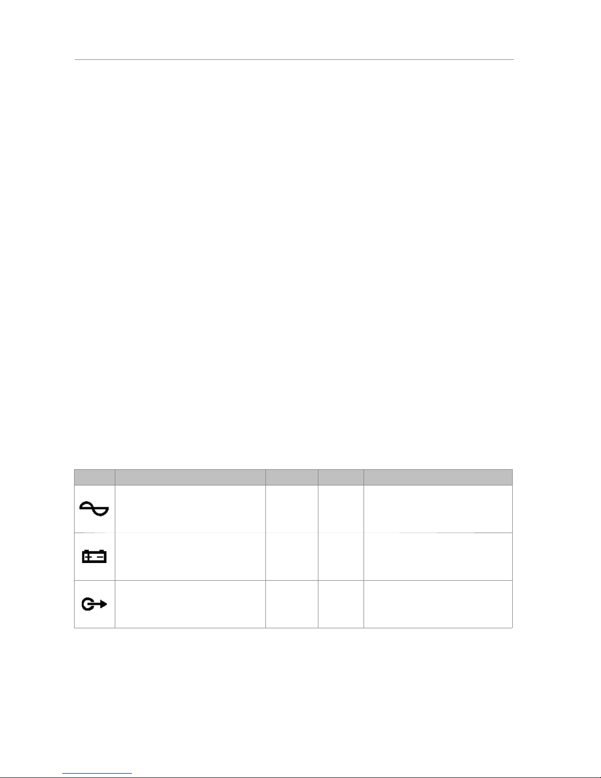
Marking Description Type Signals Activation
OV-x Attenuation of attenuators output Output
+ -
24V dc 40mA
Table 5: Attenuators override outputs
NOTE: The average consumption of the attenuator override signal is 10mA per unit.
(*): The output voltage could vary between 20 and 27V depending on the state of the battery.
(b) END OF LINE INPUTS
The equipment has 8 dual inputs for connecting
end-of-line devices. Each input has 3 terminals, one
common and two terminals for lines A and B,
associated with the same amplifier channel (CH-x).
When the activation signal occurs at one of the inputs,
a loudspeaker line failure will be detected.
The connection is via 8-pin female euroblock
connector with 3 contact of 3.81 mm pitch (supplied
with the unit). The wire size range for each pole of this
connector is: 0.14 1.5 mm2 (30 14 AWG).
Marking Description Type sSignal Activation
CH-x End-of-line device input Input
┴ A B
Voltage-free contact closure ┴ A
Voltage-free contact closure ┴ B
Table 6:EOL device inputs
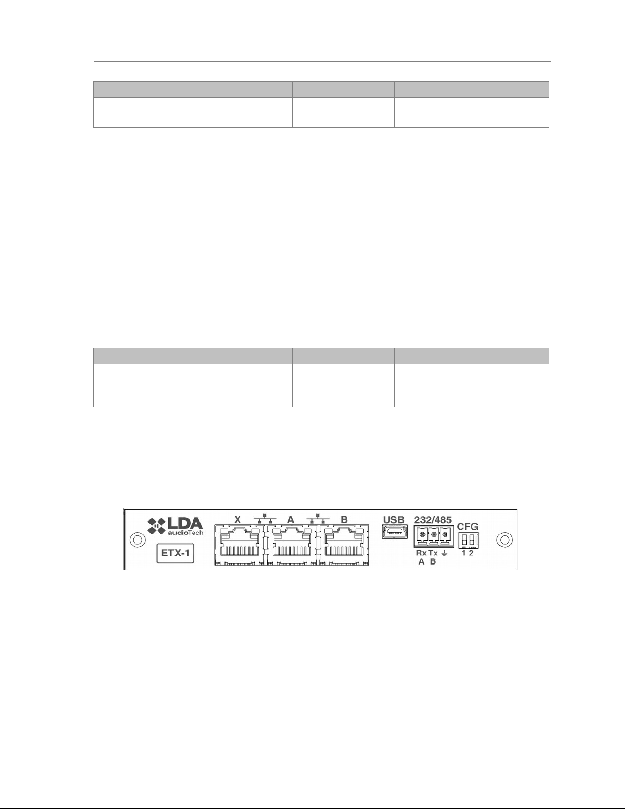
2.4.4 EXTERNAL SYSTEMS SLOT INTERFACE
The equipment has a slot where the ETX-1 module can be integrated. This module
allows connection to NEO-Extension units, the control, monitoring and configuration through
the data network, the reception of audio sources from the data network and the integration with
third-party systems. The ETX-1 module is delivered as part of the equipment.
(a) SYSTEM CONNECTION PORT X
The X port allows the connection of an external Ethernet network that can be used for
control, monitoring and configuration and the reception of audio over the data network. It is
possible to configure this port to be disabled during emergency mode, therefore enhancing the
security in the internal network.
(b) SYSTEM CONNECTION PORTS A AND B
The equipment has two ports for the connection with other systems and NEOExtension units. The behavior of this ports can be configured by a dip-switch as indicated in
section (e). The default mode will be position 01, where A will be the main Flexnet connection
and B the redundant Flexnet connection. In case of failure in port A, the system will
automatically switch to port B.
LDA Audio Tech - Severo Ochoa Nº 31- 29590 MÁLAGA, ESPAÑA. Tlf: +34 952028805
11
Picture 14: EOL device inputs
Picture 15: External Systems Slot Interface
User's Manual: EN 54-16 PA/VA System LDA NEO

The connection is made using standard CAT 5 Ethernet network cable RJ-45 T568B
(the connection cable is supplied with the equipment).
MarkingDescription Type Signals Activation
X/A/B Ports for system connection Port
Ethernet
CAT5
Flexnet (propriety protocol)
UDP
Cobranet
Table 7: System connection ports
(c) USB PORT (reserved)
The USB port (mini USB type AB) integrated in the equipment
is reserved.
(d) INTEGRATION SERIAL PORT
The equipment has a two-wire RS-485 serial port.
The default configuration for events for integration with third
party systems is: 19200bps, 8 bits, even party bit, 1 stop bit.
The commands admitted in this port can trigger events in
the system that can be configured through the configuration
application.
NOTE: If configured for use of LDA VCC units, this port
could not be used for other devices.
The connection is made using a 3-pin female euroblock connector and pitch 3.81 mm
(supplied with the unit). The wire size range for each pole of this connector is: 0.14 1.5 mm2
(30 14 AWG). It is recommended to use twisted pair cabling for the connection of serial
signals.
Marking Description Type Signals Activation
485-AB
Terminal A and B, Serial
connection port for RS-485
integration
Port AB
Standard RS-485/9600/8/N/1
see configuration software.
485 ┴
Cable net drape NA NA NA
Table 7: Integration serial port
NOTE: The 232 marking corresponds to a reserved future use.
(e) SYSTEM CONNECTION CONFIGURATION SWITCH
The equipment has a dip-switch for configuring the behavior of the system connection
ports. Depending on the position according to the following table
12
www.lda-audiotech.com
Picture 17: Integration Serial Port
User's Manual: EN 54-16 PA/VA System LDA NEO
Picture 16: USB Port

Marking Description Type Signals Activation
CFG
Port A : Control data exclusively
Puert B : Audio data exclusively
Puert X : Flexnet**
Config. NA Posición 00
CFG
Puert A : Flexnet**
Puert B : Flexnet**
Puert X : Control data exclusively
Config. NA Posición 01
CFG
Puert A : Flexnet**
Puert B : Flexnet**
Puert X : Audio data exclusively
Config. NA Posición 10
CFG
Puert A : Flexnet**
Puert B : Flexnet**
Puert X : Flexnet**
Config. NA Posición 11
Table 8: System connection configuration
*NOTE 1: in NEO 8060, port B will be normally inactive in modes 01,10 and 11 for avoiding
the storm effect in the Flexnet network ring. It will only operate when detecting a disconnection of a
NEO-Extension unit in the bus.
**NOTE 2: Flexnet mode will have Control Data in VLAN1 + Audio Data in VLAN2. For
more information about Flexnet, see chapter 4.3.
LDA Audio Tech - Severo Ochoa Nº 31- 29590 MÁLAGA, ESPAÑA. Tlf: +34 952028805
13
User's Manual: EN 54-16 PA/VA System LDA NEO
 Loading...