

LD WIN42HUB User Manual
USER´S MANUAL
BEDIENUNGSANLEITUNG
MANUEL D`UTILISATION
MANUAL DE USUARIO
INSTRUKCJA OBSŁUGI
MANUALE D‘ USO
LD WIN42 CONTROLLER HUB
WIN42HUB
POWER
WIN42 CONTROLLER HUB
COM

2
ENGLISHDEUTSCHFRANCAIS
FRANCAISFRANCAIS FRANCAISFRANCAIS
ESpAñoLpoLSKIITALIANo
Thank you for choosing LD-Systems!
We have designed this product to operate reliably over many years. Therefore LD-Systems guarantees for high
quality products with its name and many years of experience as a producer.
Please, take a few moments to read these instructions carefully, as we want you to enjoy your new LD-Systems
products quickly and to the fullest.
For information about LD-Systems check out our website WWW.LD-SYSTEMS.COM
Introduction
The LD Systems WIN42HUB and the associated WIN42 CONTROL CENTER software enable you to monitor and
control up to 16 WIN42 wireless systems. Clearly arranged graphics give you control over the radio frequency,
battery status, audio level, and much more for each individual WIN42 wireless systems connected. In addition,
the software has an "environment scan" feature with the help of which you can scan the respective location for
unused frequencies.

3
ITALIANOPOLSKIESPAÑOL
FRANCAISFRANCAIS FRANCAISFRANCAIS
FRANCAISDEUTSCHENGLISH
POWER
WIN42 CONTROLLER HUB
COM
LD WIN42HUB
WIN42HUB

4
ENGLISHDEUTSCHFRANCAIS
FRANCAISFRANCAIS FRANCAISFRANCAIS
ESpAñoLpoLSKIITALIANo
1. Please read this information carefully.
2. Keep all information and instructions in a safe place.
3. Please follow the instructions.
4. Please observe all warnings. Don‘t remove safety instructions or any other information located on the device.
5. Use the device only in the intended manner.
6. Use only stable and appropriate stands and/or mounts when the device is permanently installed. Make certain
that wall brackets are firmly secured. Make certain that the unit is installed securely and cannot fall down.
7. When installing please observe the corresponding safety standards for your country.
8. Do not install the device near radiators, heat accumulators, ovens or other sources of heat. Make certain that
the device is always installed so that is cooled sufficiently and cannot overheat.
9. Do not place open sources of ignition, e.g., burning candles, on the device.
10. Do not cover ventilation slots.
11. Do not operate the device in the immediate vicinity of water. Do not expose this equipment to combustible
materials, liquids or gases.
12. Please make certain that dripping or splashing water cannot get inside the device. Do not put objects filled
with fluids, such as vases or drinking vessels, on top of the device.
13. Make certain that objects cannot fall into the device.
14. Use the device only with accessories with which the manufacturer intends the device to be used.
15. CAUTION: If this device has a mains connector equipped with protective earth, it must be connected to a
mains socket with a protective ground connection. Never disable the function of the protective ground connection
of the included power cord.
16. Do not turn on the device immediately if it was exposed to strong temperature fluctuations (for example after
transportation). Moisture and condensation may damage the device. Leave the device switched off until it has
reached room temperature.
17. Do not open the device and do not make any changes to the device.
18. Before connecting to mains power, make certain that the mains voltage and the mains frequency are the
same as the operating values of the device (see type label). If the device is equipped with a supply voltage selector switch, make certain that the values of the device match the values of the mains power before connecting.
If the plug on the included cord does not fit your mains outlet, contact your electrician.
19. Make certain that the power cord is not stepped on. Protect the power cord against pinching, especially at
the device plug and the power plug.
20. In order to prevent damage or accidents, for example, due to tripping hazards, check all connections once
you have connected the device.
21. When connecting the device, make certain that the power plug remains readily accessible.
Always pull out the power plug when the device is not in use or when you clean the device. Disconnect the
power cord by pulling the plug not the cable. Never touch the power cable and power adapter with wet hands.
22. Avoid switching the device on and off at short intervals, because it may shorten the durability of the device.
23. IMPORTANT: Replace fuse only by fuse of same type and rating! If fuse blows repeatedly please contact
authorized service center!
24. In order to disconnect the device completely from the mains voltage, the power plug must be unplugged.
25. If your device is equipped with a Volex power connector, the matching Volex device plug must be unlocked
in order to disconnect it. This also means that a tug on the power cord can pull the device out of place, thus
causing personal injuries and/or property damage. Thus please make certain to route your cables carefully.
PREVENTIVE MEASURES:

5
ITALIANOPOLSKIESPAÑOL
FRANCAISFRANCAIS FRANCAISFRANCAIS
FRANCAISDEUTSCHENGLISH
ENGLISH
ITALIANOPOLSKIESPAÑOL
FRANCAIS
5
26. If there is a risk of lightning strike or during extended periods of disuse, unplug the power plug.
27. During transport, make certain that the equipment being transported cannot fall down and possibly
cause personal injuries and/or property damage.
28. If your device no longer works properly, if it has been exposed to liquids or an object has fallen inside it or
if it has been damaged in some other manner, turn the device off immediately und unplug the power plug. This
device should be repaired only by authorized experts.
29. Use only a dry cloth to clean the device.
30. Comply with all of the disposal laws that are applicable in your country. During disposal, please separate
plastic and paper/cardboard.
31. Plastic bags must be kept out of the reach of children.
CAUTION
RISK OF ELECTRIC SHOCK
DO NOT OPEN
PREVENTIVE MEASURES:
CAUTION:
To reduce the risk of electric shock, do not remove cover (or back). No user serviceable parts inside. Refer
servicing to qualified personnel.
The lightning flash with arrowhead symbol within an equilateral triangle is intended to alert the
user to the presence of uninsulated “dangerous voltage” within the product´s enclosure that may be
of sufficient magnitude to constitute a risk to persons.
The exclamation mark within an equilateral triangle is intended to alert the user to the presence of
important operating and maintenance (servicing) instructions in the literature accompanying the
appliance.
CAUTION! HIGH VOLUME!
You will operate this transmission system for professional use. Therefore the commercial use of this equipment
is liable to the rules and regulations of the Accident Prevention & Insurance Association of your industry sector.
Adam Hall as a manufacturer is bound to inform you formally about the existence of eventual sanitary risks.
Risk of hearing damage due to prolonged exposure to excessive volumes: The loudspeaker is easily capable of
generating sound pressure levels (SPL) sufficient to cause permanent hearing damage to performers, production
crew and audience members. Caution should be taken to avoid prolonged exposure SPL in excess of 90 dB.
ENGLISH

6
ENGLISHDEUTSCHFRANCAIS
FRANCAISFRANCAIS FRANCAISFRANCAIS
ESpAñoLpoLSKIITALIANo
PACKAGE CONTENTS:
1 x WIN42 CONTROLLER HUB
1 x WIN42 USB to RS485 converter
1 x USB cable
16 x RJ11 cable
1 x RJ45 cable
1 x power adapter
1 x software CD
1 x User's Manual
POWER
WIN42 CONTROLLER HUB
COM
USER´S MANUAL
BEDIENUNGSANLEITUNG
MANUEL D`UTILISATION
MANUAL DE USUARIO
INSTRUKCJA OBSŁUGI
MANUALE D‘ USO
LD WIN42 CONTROLLER HUB
WIN42HUB
POWER
WIN42 CONTROLLER HUB
COM

7
ITALIANOPOLSKIESPAÑOL
FRANCAISFRANCAIS FRANCAISFRANCAIS
FRANCAISDEUTSCHENGLISH
FRONT / REAR PANEL:
1
ON / OFF SWITCH
2
INDICATOR LEDS 1-16 FOR WIN42 RECEIVERS 1-16
1
AC ADAPTER CONNECTOR (9 - 18 V DC, 300 MA)
2
DATA PORT FOR USB TO RS485 CONVERTER
3
DATA CONNECTORS (COM 1 - 16) FOR WIN42 RECEIVERS
4
PROVISION FOR PORT EXPANSION (CURRENTLY UNAVAILABLE)
FRONT PANEL
REAR PANEL
1
1
2
234
8
ENGLISHDEUTSCHFRANCAIS
FRANCAISFRANCAIS FRANCAISFRANCAIS
ESpAñoLpoLSKIITALIANo
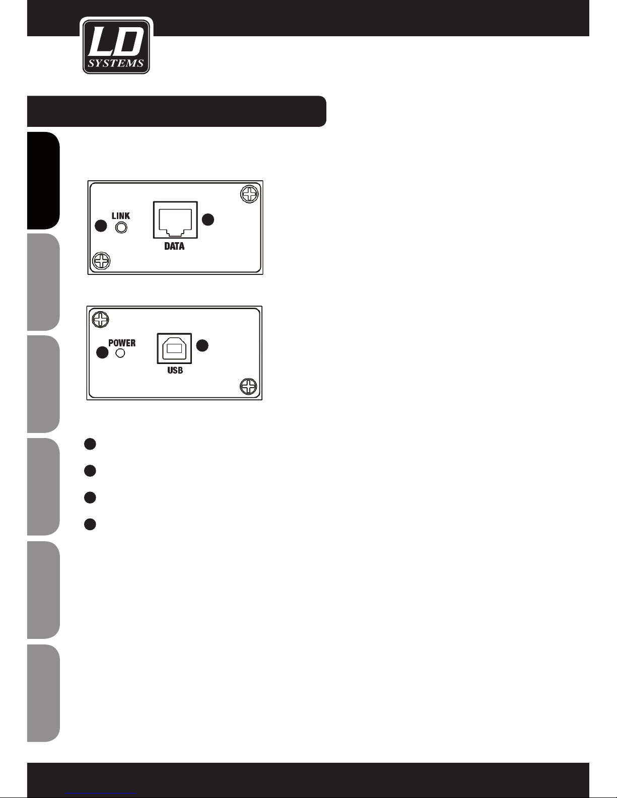
USB TO RS485 CONVERTER:
1
RJ45 PORT, CONNECTION TO THE WIN42HUB
2
USB PORT, CONNECTION TO A WINDOWS PC
3
POWER LED: LIGHTS UP WHEN THE CONVERTER IS CONNECTED CORRECTLY VIA USB.
4
LINK LED: LIGHTS UP WHEN THE CONNECTION BETWEEN CONVERTER AND CONTROLLER
HUB HAS BEEN MADE CORRECTLY.
2
1
4
3
9
ITALIANOPOLSKIESPAÑOL
FRANCAISFRANCAIS FRANCAISFRANCAIS
FRANCAISDEUTSCHENGLISH
SOFTWARE INSTALLATION:
SYSTEM REQUIREMENTS
for the WIN42 CONTROL CENTER software and the driver for the WIN42 CONTROLLER HUB: Windows XP,
Windows Vista, Windows 7 and Windows 8, an unused USB 2.0 port, and a recommended monitor resolution of
at least 1366 x 768.
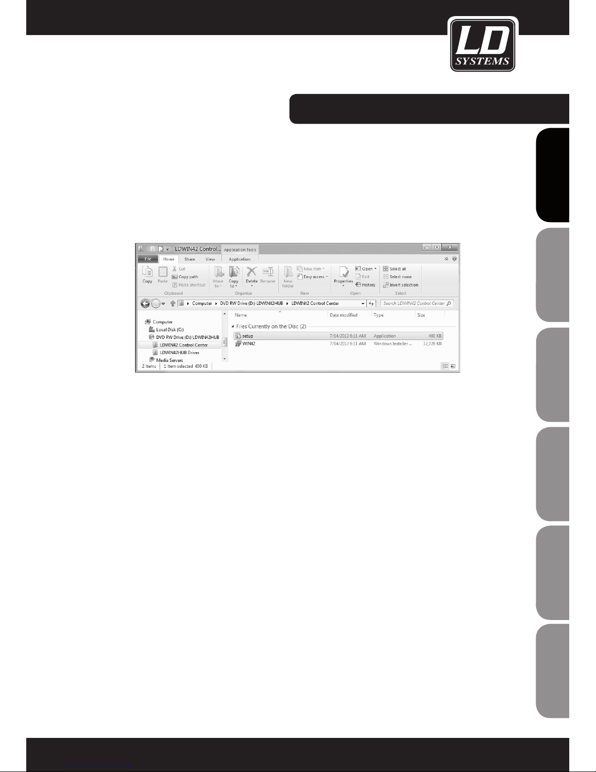
1. Insert the included software CD in the optical drive of your computer, open it, and double-click on the "Setup" file, then follow
the instructions to install the WIN42 CONTROL CENTER software on your computer.

10
ENGLISHDEUTSCHFRANCAIS
FRANCAISFRANCAIS FRANCAISFRANCAIS
ESpAñoLpoLSKIITALIANo
SOFTWARE INSTALLATION:
2. You now be prompted to click "Next" multiple times in order to carry out the installation.
Click on "Close" to complete installation.

11
ITALIANOPOLSKIESPAÑOL
FRANCAISFRANCAIS FRANCAISFRANCAIS
FRANCAISDEUTSCHENGLISH
Connect the included USB to RS485 converter to an unused USB port on your computer.
DRIVER INSTALLATION:

12
ENGLISHDEUTSCHFRANCAIS
FRANCAISFRANCAIS FRANCAISFRANCAIS
ESpAñoLpoLSKIITALIANo
DRIVER INSTALLATION:
If you see the system messages depicted on the preceding page, install the associated driver by pressing the Windows key on
your keyboard and clicking on "Control Panel".

13
ITALIANOPOLSKIESPAÑOL
FRANCAISFRANCAIS FRANCAISFRANCAIS
FRANCAISDEUTSCHENGLISH
The "Control Panel" window will open. Now click on "Hardware and Sound" and then on "Device Manager".
DRIVER INSTALLATION:
14
ENGLISHDEUTSCHFRANCAIS
FRANCAISFRANCAIS FRANCAISFRANCAIS
ESpAñoLpoLSKIITALIANo
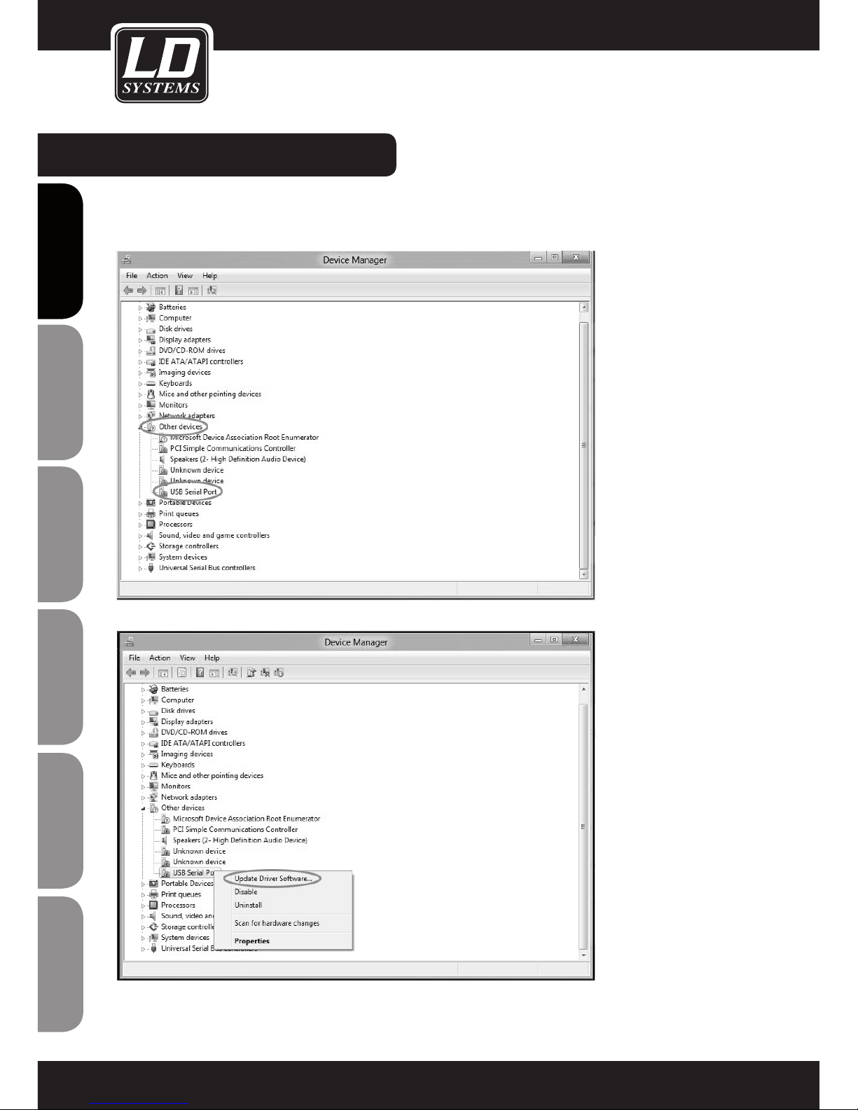
DRIVER INSTALLATION:
Once the Device Manager window has opened, click on the arrow next to "Other devices". Now click the right mouse button on
"USB serial port" and then click on "Update driver software".

15
ITALIANOPOLSKIESPAÑOL
FRANCAISFRANCAIS FRANCAISFRANCAIS
FRANCAISDEUTSCHENGLISH
Now click with the left mouse key on "Browse the computer for driver software".
Select the optical drive of your computer containing the included software and driver CD, click on "Include subfolders", and
continue the process by clicking on "Next".
DRIVER INSTALLATION:

16
ENGLISHDEUTSCHFRANCAIS
FRANCAISFRANCAIS FRANCAISFRANCAIS
ESpAñoLpoLSKIITALIANo
DRIVER INSTALLATION:
If the following message appears, click on "Install this driver software anyway".
The driver is now installed. Click on "Close" to exit the installation procedure.

17
ITALIANOPOLSKIESPAÑOL
FRANCAISFRANCAIS FRANCAISFRANCAIS
FRANCAISDEUTSCHENGLISH
Now the COM port number of the "USB serial port" will be displayed in Device Manager.
Note: The COM port number of the "USB serial port" must be between 1 and 16.
Now, using the included RJ45 cable, connect the WIN42 CONTROLLER HUB to the USB to RS485 converter and start the WIN42
CONTROL CENTER SOFTWARE. Now select the command "Communication" in the "Tools" menu to see whether the port number
of the USB serial port and the port number in the WIN42 CONTROL CENTER match (COM16 in our example).
DRIVER INSTALLATION:

18
ENGLISHDEUTSCHFRANCAIS
FRANCAISFRANCAIS FRANCAISFRANCAIS
ESpAñoLpoLSKIITALIANo
CONNECTING THE WIN42 CONTROLLER HUB:
Note: The cables (16 included in the package contents) for connecting the WIN42 CONTROLLER HUB to the WIN42 receivers have
plugs of two different sizes on each cable. The larger plug is inserted in the COM connector (1 - 16) of the WIN42 CONTROLLER
HUB, while the smaller of the two is plugged into the Data Output connector of the WIN42 receiver.
CHANNEL2
XLR BALANCED
UNBAL
OUTPUT
Data Output
ANTENNA-AANTENNA-B
CHANNEL1
XLR BALANCED
D.C 12-18V
1000mA
UNBAL
OUTPUT
Data Output
CHANNEL2
XLR BALANCED
UNBAL
OUTPUT
Data Output
ANTENNA-AANTENNA-B
CHANNEL1
XLR BALANCED
D.C 12-18V
1000mA
UNBAL
OUTPUT
Data Output
CHANNEL2
XLR BALANCED
UNBAL
OUTPUT
Data Output
ANTENNA-AANTENNA-B
CHANNEL1
XLR BALANCED
D.C 12-18V
1000mA
UNBAL
OUTPUT
Data Output
CHANNEL2
XLR BALANCED
UNBAL
OUTPUT
Data Output
ANTENNA-AANTENNA-B
CHANNEL1
XLR BALANCED
D.C 12-18V
1000mA
UNBAL
OUTPUT
Data Output
1
1
3
5
7
2
4
682345678
USB RS485
DATA CONVERTER
DATA
USB

19
ITALIANOPOLSKIESPAÑOL
FRANCAISFRANCAIS FRANCAISFRANCAIS
FRANCAISDEUTSCHENGLISH
RECEIVER INFO
1
NAME
Click here to assign a name to the receiver
2
GROUP/CHANNEL
Click here to assign the frequency and channel.
3
FREQUENCY
Displays the Group/Channel allocation assigned
under (2)
4
ADDRESS CODE
Click here to assign an address to the receiver
(0-244)
5
SQUELCH
Click here to adjust the squelch setting of the
receiver (Low/Mid/High)
6
RECEIVER VOLUME ADJUSTMENT (03-48)
BATTERY INFO
7
BATTERY STATUS DISPLAY (0-100%)
If the battery status of the transmitter nears a
critical state, the "LOW" indicator lights up.
RF INFO
8
RECEIVER RF FIELD STRENGTH INDICATOR
The active receiver of the diversity system is
indicated by the (A/B) indicators.
AF INFO
9
RECEIVER SIGNAL LEVEL INDICTOR
10
RECEIVER MUTE STATUS INDICATOR
11
EQ
Click here to change the equalizer settings of
the receiver (Flat/Low-cut/Low-cut+High-boost/
High-boost)
USING THE WIN42 CONTROL CENTER SOFTWARE:
1
2
3
4
5
6
7
8
9
10
11

20
ENGLISHDEUTSCHFRANCAIS
FRANCAISFRANCAIS FRANCAISFRANCAIS
ESpAñoLpoLSKIITALIANo
SAVING AND RETRIEVING SETTINGS
All settings that you make in the main window can be saved on your computer and retrieved at a later point in
time.
To do this, select the menu item Open Setting or Save Setting in the File menu in the main window
ENVIRONMENT SCAN
The Environment Scan function lets you scan the entire frequency spectrum of the LD Systems WIN42 system
and find unused frequencies simply and easily.
Please follow these instructions step by step in order to utilize the full scope of functionality of the software.
Select the Environment Scan function in the Tools menu
USING THE WIN42 CONTROL CENTER SOFTWARE:

21
ITALIANOPOLSKIESPAÑOL
FRANCAISFRANCAIS FRANCAISFRANCAIS
FRANCAISDEUTSCHENGLISH
The following functions are available in the Environment Scan window (sample depiction of environment scan)
1
6
7
8
9
3
5
2
4
SCAN MENU
1
PORT
Select the port of one of the connected receivers that is to be used for scanning. Note: This receiver cannot
be used for any other function during scanning.
2
START SCAN
Starts the scanning procedure. The receiver defined in the port selection is used to scan the environment.
The receiver RF field strength is displayed directly in the graph. The entire procedure may take several
minutes.
If the scanning procedure cannot be started, then the message "Scan timeout" appears. In this case, make
certain that the proper port (1) is selected and the receiver is correctly connected and working.
3
STOP
Stops the scanning procedure.
4
SAVE PIC
Click here to save the scan results as a graphics file (*.jpg) on your computer.
5
SCAN TABLE
Click here to view the scan results in tabular form and allocate unused frequencies to the connected
receivers. See also the section "Scan Table".
6
SHOW GRID
Toggles the coordinate grid in the display on and off.
USING THE WIN42 CONTROL CENTER SOFTWARE:

22
ENGLISHDEUTSCHFRANCAIS
FRANCAISFRANCAIS FRANCAISFRANCAIS
ESpAñoLpoLSKIITALIANo
7
ZOOM IN
Click here to zoom in on a section of the scan results. Use the mouse to mark the area to be enlarged.
8
AUTO COORDINATE
Click here to toggle the automatic adjustment of the coordinates on or off.
9
DEFAULT COORDINATE
Click her to leave the zoom view and return to the default view.
SCAN TABLE
(Sample depiction of scan table)
In this view, you can find frequencies and assign them to the connected receivers.
Carry out the environment scan as described above and click on Scan Table to view the scan results in tabular
form. Here you will find all available frequency groups with the associated frequencies. The results of the
environment scan are shown for each frequency as the value of the measured field strength. The available
frequencies in the desired group are also identified by coloured markings.
White: Receiver field strength 0dBuV or less unused frequency
Yellow: receiver field strength 0dBuV to 20dBuV frequency possibly in use
Red: Receiver field strength 20dBuV or greater frequency in use
To be able to access the results at a later point in time, save the scan table by clicking on the Save button at the
lower right edge of the screen.
To open a previously saved scan table , select the menu item Open RF File in the File menu in the main menu.
FREQUENCY ALLOCATION
Double-click on a frequency that you want to assign to one of the connected receivers. Afterwards, you will be
returned to the main screen automatically.
USING THE WIN42 CONTROL CENTER SOFTWARE:

23
ITALIANOPOLSKIESPAÑOL
FRANCAISFRANCAIS FRANCAISFRANCAIS
FRANCAISDEUTSCHENGLISH
The blinking of the receiver number indicates to which receiver the selected frequency can be assigned. Select
a receiver by clicking on the corresponding receiver number. The selected frequency from the scan table will be
assigned to the desired receiver.
Repeat this operation until frequencies have been allocated to all available receivers. To synchronize the
receivers that you have now programmed with their transmitters, use the sync function of the receiver or set the
frequency manually at the transmitter.
USING THE WIN42 CONTROL CENTER SOFTWARE:

24
ENGLISHDEUTSCHFRANCAIS
FRANCAISFRANCAIS FRANCAISFRANCAIS
ESpAñoLpoLSKIITALIANo
Product type Controller for WIN42 wireless systems
Type software-based
Number of supported wireless systems 16
Indicators 16 x LED activation indicator
Operating voltage 9 V - 18 V DC, 300 mA
Width 482 mm
Height 44 mm
Depth 160 mm
Weight 1850 g
Included accessories USB to RS485 converter, 1 x USB cable, 16 x RJ11 cable, 1 x RJ45 cable, 1 x
power adapter, software CD
SPECIFICATIONS:

25
ITALIANOPOLSKIESPAÑOL
FRANCAISFRANCAIS FRANCAISFRANCAIS
FRANCAISDEUTSCHENGLISH
LIMITED WARRANTY
This Limited Warranty applies to the Adam Hall, LD Systems, LD Premium, Defender, Palmer, Cameo and Eminence
branded products.
The statutory warranty rights towards the seller are not affected by this guarantee. In fact, it justifies, additional
independent warranty claims towards Adam Hall.
Adam Hall warrants that the Adam Hall product you have purchased from Adam Hall or from an Adam Hall authorized reseller is free from defects in materials or workmanship under normal use for a period of 2 or 5 years from
the date of purchase.
The Limited Warranty Period starts on the date of purchase. In order to receive warranty services you are required
to provide proof of the purchase date. Your dated sales or delivery receipt, showing the date of purchase, is your
proof of the purchase date. Should products of the brands named above be in need of repair within the limited warranty period, you are entitled to warranty services according to the terms and conditions stated in this document.
This Limited Warranty extends only to the original purchaser of this Adam Hall branded product and is not transferable to anyone who obtains ownership of the Adam Hall branded product from the original purchaser. During
the Limited Warranty Period, Adam Hall will repair or replace the defective component parts or the product. All
component parts or hardware products removed under this Limited Warranty become the property of Adam Hall.
In the unlikely event that your Adam Hall product has a recurring failure, Adam Hall, at its discretion, may elect to
provide you with a replacement unit of Adam Hall´s choice that is at least equivalent to your Adam Hall branded
product in hardware performance.
Adam Hall does not warrant that the operation of this product will be uninterrupted or error-free. Adam Hall is not
responsible for damage that occurs as a result of your failure to follow the instructions included with the Adam
Hall branded product.
This Limited Warranty does not apply,
- to wear parts (e.g. accumulator)
- to any product from which the serial number has been removed or that has been damaged or rendered defective as the result of an accident
- in case of, misuse, abuse, or other external causes
- by operation outside the usage parameters stated in the user´s documentation shipped with the product by use
of spare parts not manufactured or sold by Adam Hall
- by modification or service by anyone other than Adam Hall
These terms and conditions constitute the complete and exclusive warranty agreement between you and Adam
Hall regarding the Adam Hall branded product you have purchased.
MANUFACTURER´S DECLARATIONS:

26
ENGLISHDEUTSCHFRANCAIS
FRANCAISFRANCAIS FRANCAISFRANCAIS
ESpAñoLpoLSKIITALIANo
MANUFACTURER´S DECLARATIONS:
LIMITATION OF LIABILITY
If your Adam Hall branded hardware product fails to work as warranted above, your sole and exclusive remedy
shall be repair or replacement. Adam Halls’ maximum liability under this limited warranty is expressly limited
to the lesser of the price you have paid for the product or the cost of repair or replacement of any hardware
components that malfunction in conditions of normal use.
Adam Hall is not liable for any damages caused by the product or the failure of the product, including any lost
profits or savings or special, incidental, or consequential damages. Adam Hall is not liable for any claim made by
a third party or made by you for a third party.
This limitation of liability applies whether damages are sought, or claims are made, under this Limited Warranty
or as a tort claim (including negligence and strict product liability), a contract claim, or any other claim. This limitation of liability cannot be waived or amended by any person. This limitation of liability will be effective even if
you have advised Adam Hall of an authorized representative of Adam Hall of the possibility of any such damages.
This limitation of liability however, will not apply to claims for personal injury.
This Limited Warranty gives you specific legal rights. You may also have other rights that may vary from state to
state or from country to country. You are advised to consult applicable state or country laws for a full determination of your rights.
REQUESTING WARRANTY-SERVICE
To request warranty service for the product, contact Adam Hall or the Adam Hall authorized reseller from which
you purchased the product.
EC DECLARATION OF CONFORMITY
These devices meet the essential requirements and further relevant specifications of Directives 2004/108/EC
(EMC) and 2006/95/EC (LVD). For more information, see www.adamhall.com.
CORRECT DISPOSAL OF THIS PRODUCT (ELECTRICAL WASTE)
(Applicable in the European Union and other European countries with separate collection systems)
This marking shown on the product or its literature, indicates that it should not be disposed with other household
wastes at the end of its working life. To prevent possible harm to the environment or human health from uncontrolled waste disposal, please separate this from other types of wastes and recycle it responsibly to promote the
sustainable reuse of material resources.
Household users should contact either the retailer where they purchased this product, or their local government
office, for details on where and how they can recycle this item in an enviromentally friendly manner.
Business users should contact their supplier and check the terms and conditions of the purchase contract. This
product should not be mixed with other commercial wastes for disposal.

27
ITALIANOPOLSKIESPAÑOL
FRANCAISFRANCAIS FRANCAISFRANCAIS
FRANCAISDEUTSCHENGLISH
WEEE-DECLARATION
Your LD-Systems product was developed and manufactured with high quality materials and components wich
can be recycled and/or reused. This symbol indicates that electrical and electronic equipment must be disposed
of separately from normal waste at the end of its operational lifetime.
Please dispose of this product by bringing it to your local collection point or recycling centre for such equipment.
This will help to protect the environment in which we all live.
BATTERIES AND ACCUMULATORS
The supplied batteries or rechargeable batteries can be recycled. Please dispose of them as special waste or
return them to your specialist dealer. In order to protect the environment, only dispose exhausted batteries.
ECOLOGY AND ENERGY SAVING
Saving electric energy helps to protect the environment. Please turn off all electrical equipment when it is not in
use. To avoid power consumption in idle mode, disconnect all electrical equipment from mains when not in use.
Adam Hall GmbH, all rights reserved. The technical data and the functional product characteristics can be subject
to modifications. The photocopying, the translation, and all other forms of copying of fragments or of the integrality of this user’s manual is prohibited.
MANUFACTURER´S DECLARATIONS:

ENGLISHDEUTSCHFRANCAIS
FRANCAISFRANCAIS FRANCAISFRANCAIS
ESpAñoLpoLSKIITALIANo
28
Sie haben die richtige Wahl getroffen!
Dieses Gerät wurde unter hohen Qualitätsanforderungen entwickelt und gefertigt, um viele Jahre einen reibungslosen Betrieb zu gewährleisten. Dafür steht LD Systems mit seinem Namen und der langjährigen Erfahrung als
Hersteller hochwertiger Audioprodukte.
Bitte lesen Sie diese Bedienungsanleitung sorgfältig, damit Sie Ihr neues Produkt von LD Systems schnell optimal
einsetzen können.
Mehr Informationen zu LD-SYSTEMS finden Sie auf unserer Internetseite WWW.LD-SYSTEMS.COM
Einführung
Der LD Systems WIN42HUB und die dazugehörige Software WIN42 CONTROL CENTER bietet Ihnen die
Möglichkeit, bis zu 16 WIN42 Funkstrecken zu überwachen und zu steuern. In übersichtlichen Grafiken haben
Sie Funkfrequenz, Batteriestatus, Funksignal, Audiopegel und vieles mehr jeder einzelnen angeschlossenen
WIN42 Funkstrecke unter Kontrolle. Darüber hinaus bietet die Software einen "Environment Scan" mit dessen
Hilfe der jeweilige Standort nach freien Empfangsfrequenzen abgesucht werden kann.

ITALIANOPOLSKIESPAÑOL
FRANCAISFRANCAIS FRANCAISFRANCAIS
FRANCAISDEUTSCHENGLISH
29
POWER
WIN42 CONTROLLER HUB
COM
LD WIN42HUB
WIN42HUB

ENGLISHDEUTSCHFRANCAIS
FRANCAISFRANCAIS FRANCAISFRANCAIS
ESpAñoLpoLSKIITALIANo
30
SICHERHEITSHINWEISE:
1. Lesen Sie diese Anleitung bitte sorgfältig durch.
2. Bewahren Sie alle Informationen und Anleitungen an einem sicheren Ort auf.
3. Befolgen Sie die Anweisungen.
4. Beachten Sie alle Warnhinweise. Entfernen Sie keine Sicherheitshinweise oder andere Informationen vom Gerät.
5. Verwenden Sie das Gerät nur in der vorgesehenen Art und Weise.
6. Verwenden Sie ausschließlich stabile und passende Stative bzw. Befestigungen (bei Festinstallationen). Stellen
Sie sicher, dass Wandhalterungen ordnungsgemäß installiert und gesichert sind. Stellen Sie sicher, dass das
Gerät sicher installiert ist und nicht herunterfallen kann.
7. Beachten Sie bei der Installation die für Ihr Land geltenden Sicherheitsvorschriften.
8. Installieren und betreiben Sie das Gerät nicht in der Nähe von Heizkörpern, Wärmespeichern, Öfen oder
sonstigen Wärmequellen. Sorgen Sie dafür, dass das Gerät immer so installiert ist, dass es ausreichend gekühlt
wird und nicht überhitzen kann.
9. Platzieren Sie keine Zündquellen wie z.B. brennende Kerzen auf dem Gerät.
10. Lüftungsschlitze dürfen nicht blockiert werden.
11. Betreiben Sie das Gerät nicht in unmittelbarer Nähe von Wasser. Bringen Sie das Gerät nicht mit brennbaren
Materialien, Flüssigkeiten oder Gasen in Berührung.
12. Sorgen Sie dafür, dass kein Tropf- oder Spritzwasser in das Gerät eindringen kann. Stellen Sie keine mit
Flüssigkeit gefüllten Behältnisse wie Vasen oder Trinkgefäße auf das Gerät.
13. Sorgen Sie dafür, dass keine Gegenstände in das Gerät fallen können.
14. Betreiben Sie das Gerät nur mit dem vom Hersteller empfohlenen und vorgesehenen Zubehör.
15. ACHTUNG: Wenn das Netzkabel des Geräts mit einem Schutzkontakt ausgestattet ist, muss es an einer
Steckdose mit Schutzleiter angeschlossen werden. Deaktivieren Sie niemals den Schutzleiter eines Netzkabels.
16. Schalten Sie das Gerät nicht sofort ein, wenn es starken Temperaturschwankungen ausgesetzt war (beispielsweise nach dem Transport). Feuchtigkeit und Kondensat könnten das Gerät beschädigen. Schalten Sie das
Gerät erst ein, wenn es Zimmertemperatur erreicht hat.
17. Öffnen Sie das Gerät nicht und verändern Sie es nicht.
18. Bevor Sie das Gerät an die Steckdose anschließen, prüfen Sie zuerst, ob die Spannung und die Frequenz
des Stromnetzes mit den auf dem Gerät angegebenen Werten übereinstimmen. Verfügt das Gerät über einen
Spannungswahlschalter, schließen Sie das Gerät nur an die Steckdose an, wenn die Gerätewerte mit den Werten
des Stromnetzes übereinstimmen.
Wenn das mitgelieferte Netzkabel bzw. der mitgelieferte Netzadapter nicht in Ihre Netzsteckdose passt, wenden
Sie sich an Ihren Elektriker.
19. Treten Sie nicht auf das Netzkabel. Sorgen Sie dafür, dass spannungsführende Kabel speziell an der Netzbuchse bzw. am Netzadapter und der Gerätebuchse nicht geknickt werden.
20. Überprüfen Sie nach dem Anschluss des Geräts alle Kabelwege, um Schäden oder Unfälle, z. B. durch
Stolperfallen zu vermeiden.
21. Achten Sie bei der Verkabelung des Geräts immer darauf, dass das Netzkabel bzw. der Netzadapter stets frei
zugänglich ist. Trennen Sie das Gerät stets von der Stromzuführung, wenn das Gerät nicht benutzt wird, oder Sie
das Gerät reinigen möchten.
Ziehen Sie Netzkabel und Netzadapter immer am Stecker bzw. am Adapter und nicht am Kabel aus der Steckdose. Berühren Sie Netzkabel und Netzadapter niemals mit nassen Händen.
22. Schalten Sie das Gerät möglichst nicht schnell hintereinander ein und aus, da sonst die Lebensdauer des
Geräts beeinträchtigt werden könnte.
 Loading...