

LD SAT242, SAT42, SAT62, SAT82, SUB88 User Manual
...
USER´S MANUAL
BEDIENUNGSANLEITUNG
MANUEL D`UTILISATION
MANUAL DE USUARIO
INSTRUKCJA OBSŁUGI
LD SAT/SUB SERIES
INSTALLATIONS SPEAKER PASSIVE: SAT42 / SAT242 / SAT62 / SAT82 / SUB88
INSTALLATIONS SPEAKER ACTIVE: SAT62A / SUB10A / SUB88A
ENGLISHDEUTSCHFRANCAIS
FRANCAISFRANCAIS FRANCAISFRANCAIS
ESPAÑOLPOLSKIITALIANO
2
Thank you for choosing LD-Systems!
We have designed this product to give you reliable operation over many years. Therefore LD-Systems underwrites
high quality products with its name and many years of experience as a producer.
Please, take a few moments to read these instructions carefully, as we want you to enjoy your new LD-Systems
products quickly and to the fullest.
Further information about LD-Systems check our website WWW.LD-SYSTEMS.COM

ITALIANOPOLSKIESPAÑOL
FRANCAISFRANCAIS FRANCAISFRANCAIS
FRANCAISDEUTSCHENGLISH
3
LD SAT/SUB SERIES
INSTALLATIONS SPEAKER PASSIVE: SAT42 / SAT242 / SAT62 / SAT82 / SUB88
INSTALLATIONS SPEAKER ACTIVE: SAT62A / SUB10A / SUB88A

ENGLISHDEUTSCHFRANCAIS
FRANCAISFRANCAIS FRANCAISFRANCAIS
ESPAÑOLPOLSKIITALIANO
4
PREVENTIVE MEASURES:
1. Please read this information carefully.
2. Keep all information and instructions in a safe place.
3. Please follow the instructions.
4. Please observe all warnings.
5. Use the device only in the intended manner.
6. Use only stable and appropriate stands and/or mounts when the device is permanently installed. Make certain
that wall brackets are firmly secured.
Make certain that the unit is installed securely and cannot fall down.
8. Do not install the device near radiators, heat accumulators, ovens or other sources of heat. Make certain that
the device is always installed so that is cooled sufficiently and cannot overheat.
9.Do not place open sources of ignition, e.g., burning candles, on the device.
10.Do not cover ventilation slots.
11.Do not operate the device in the immediate vicinity of water.
12. Please make certain that dripping or splashing water cannot get inside the device. Do not put objects filled
with fluids, such as vases or drinking vessels, on top of the device.
13. Make certain that objects cannot fall into the device.
14. Use the device only with accessories with which the manufacturer intends the device to be used.
15. CAUTION: If your device is equiped with an IEC socket (PROTECTION CLASS I), it must be connected to a
mains socket with a protective ground connection. Never disable the function of the protective ground connection
of the included power cord.
If the plug on the included cord does not fit your mains outlet, contact your electrician.
16. Make certain that the power cord is not stepped on. Protect the power cord against pinching, especially at
the device plug and the power plug.
17. In order to prevent damage or accidents, for example, due to tripping hazards, check all connections once
you have connected the device.
18. When connecting the device, make certain that the power plug remains readily accessible.
19. In order to disconnect the device completely from the mains voltage, the power plug must be unplugged.
20. If your device is equipped with a Volex power connector, the matching Volex device plug must be unlocked
in order to disconnect it. This also means that a tug on the power cord can pull the device out of place, thus
causing personal injuries and/or property damage. Thus please make certain to route your cables carefully.
21. If there is a risk of lighting strike or during extended periods of disuse, unplug the power plug.
22. During transport, make certain that the equipment being transported cannot fall down and possibly cause
personal injuries and/or property damage.
23. If your device no longer works properly, if it has been exposed to liquids or an object has fallen inside it or
if it has been damaged in some other manner, turn the device off immediately und unplug the power plug. This
device should be repaired only by authorized experts.
24. Use only a dry cloth to clean the device.
25. Comply with all of the disposal laws that are applicable in your country. During disposal, please separate
plastic and paper/cardboard.
26. Plastic bags must be kept out of the reach of children.
ITALIANOPOLSKIESPAÑOL
FRANCAISFRANCAIS FRANCAISFRANCAIS
FRANCAISDEUTSCHENGLISH
5
CAUTION
RISK OF ELECTRIC SHOCK
DO NOT OPEN
CAUTION:
To reduce the risk of electric shock, do not remove cover (or back). No user serviceable parts inside. Refer
servicing to qualified personnel.
The lightning flash with arrowhead symbol within an equilateral triangle is intended to alert the
user to the presence of uninsulated “dangerous voltage” within the product´s enclosure that may be
of sufficient magnitude to constitute a risk to persons.
The exclamation mark within an equilateral triangle is intended to alert the user to the presence of
important operating and maintenance (servicing) instructions in the literature accompanying the
appliance.
CAUTION! HIGH VOLUME!
You will operate this transmission system for professional use. Therefore the commercial use of this equipment
is liable to the rules and regulations of the Accident Prevention & Insurance Association of your industry sector.
Adam Hall as a manufacturer is bound to inform you formally about the existence of eventual sanitary risks.
Hearing damage, prolonged exposure to excessive SPL, the loudspeaker is easily capable of generating sound
pressure levels (SPL) sufficient to cause permanent hearing damage to performers, production crew and audience members. Caution should be taken to avoid prolonged exposure SPL in excess of 90 dB.

ENGLISHDEUTSCHFRANCAIS
FRANCAISFRANCAIS FRANCAISFRANCAIS
ESPAÑOLPOLSKIITALIANO
6
PASSIVE SPEAKER
LD SAT42(W) / SAT242(W)
Up to 4 SAT42(W) (up to 2 SAT242(W) ) loudspeakers per power amp output can be connected in parallel on 4
ohms. At the rear connection terminal, the loudspeaker signal is simply looped through to the next SAT42(W)
(SAT242(W) ) speaker.
LD SAT62(W)
Up to 4 SAT62(W) loudspeakers per power amp output can be connected in parallel 4 ohms. At the rear connection terminal, the loudspeaker signal is simply looped through to the next SAT62(W) speaker.
LD SAT82(W)
2 pieces of SAT82(W) loudspeakers per power amp output can be connected in parallel 4 ohms. At the rear
connection terminal, the loudspeaker signal is simply looped through to the next SAT82.
LD SUB88 in connection with the LD SAT 42/242/62(W)
Connect the loudspeaker cables coming from the power amplifier to the subwoofer connection terminals labelled
Input A and B. Then connect the satellites SAT42/242(W) or SAT62(W) to the connection terminals labelled Output
A and B. Up to 4 SAT42(W) / SAT62(W) or up to 2 SAT242(W) satellites can be connected in this combination on
4 ohms. We recommend loudspeaker cables such as the Adam Hall KLS 215, with a cross-section of at least 2 x
1.5 mm².
OPERATINg INfORMATION:
ACTIVE SPEAKER
LD SAT62A
MOUNTING / INSTALLATION
It is recommended to switch the system to ON as the last one and to OFF as the first one to prevent start-up
noise caused by a connected device like a mixer etc.. Additional connected LD SAT62A should be switched to ON
in order from the first to the last one and should be switched to OFF in reversed order. If the AUTO mode is used
the source should be turned to off only after 10 minutes without any signal to make sure, that the connected LD
SAT62A are in Standby mode.
CONNECTING AND OPERATING
To connect the LD SAT62A the device should be turned to OFF. There is a connection using 6.3 mm jacks (balanced triple pole / unbalanced two pole) possible as well as a balanced connection using triple pole XLR plugs.
After connecting all necessary cables and the MAIN LEVEL adjust is turned counterclockwise to left end stop the
source device can be turned to on. Then the LD SAT62A can be turned to ON too (see above). Please turn the
MAIN LEVEL adjust clockwise until designated level is reached. Please do so for additional LD SAT62A if used.
The Connection and operating elements of LD SAT62A are shown on the back panel active speakers page.
SIGNAL LOOPING
The LD SAT62A system is designed to loop the signal to additional devices via triple pole XLR cable. It is not
necessary to connect each device using an own connection to the source. Please make sure that XLR cables of a
good quality are used and that the cables are installed in safe way.

ITALIANOPOLSKIESPAÑOL
FRANCAISFRANCAIS FRANCAISFRANCAIS
FRANCAISDEUTSCHENGLISH
7
SPECIFICATIONS:
LD SAT42(W) LD SAT242(W) LD SAT62(W) LD SAT82(W) LD SAT62A
Product Installation speaker Installation speaker Installation speaker Installation speaker Installation speaker
Type passive passive passive passive active/bass reflex
Loudspeaker
4“ woofer & 1“ silkdome
tweeter
2 x 4“ woofer & 1“ silkdo-
me tweeter
6.5“ woofer & 1“
silkdome tweeter
8“ woofer & 1“ horn
tweeter
6.5” woofer & 1“
silkdome tweeter
Amplifier - - - - Class A/B
Dispersion 60° x 60° 60° x 60° 60° x 60° 60° x 60° 60° x 60°
Load capacity (RMS
/ max.)
60/100W 100/180W 80/130W 120/200W 50W
Frequency range 75Hz-20.000Hz 75Hz-20.000Hz 55Hz-20.000Hz 50Hz-20.000Hz 55Hz-20.000Hz
SPL 85 dB 88 dB 89 dB 93 dB 89 dB
Max. SPL 103 dB 108 dB 108 dB 114 dB 108 dB
Protection circuit - - - - excess current
Line in - - - -
sym. XLR / 6.3 mm
Jack
Line out - - - - sym. XLR
Power Input - - - - 220-240 V AC
Impedance 16ohms 8ohms 16ohms 8ohms -
Terminals Clamp-type connection Clamp-type connection Clamp-type connection Clamp-type connection -
Cabinet material 12 mm MDF 12 mm MDF 12 mm MDF 15 mm MDF 12 mm MDF
Cabinet surface textured paint textured paint textured paint textured paint textured paint
Dimension (WxHxD) 140 x 230 x 125 mm 140 x 378 x 135 mm 200 x 320 x 200 mm 247 x 410 x 243 mm 200 x 320 x 205 mm
Weight 2.7 kg 4.1 kg 4.1 kg 8.5 kg 6 kg
Accessories
4 M6 rigging/mounting
points, mounting brackets
4 M6 rigging/mounting
points, mounting brackets
4 M6 rigging/moun-
ting points, mounting
brackets
4 M6 rigging/mounting
points, mounting brackets
4 M6 rigging/moun-
ting points, mounting
brackets

ENGLISHDEUTSCHFRANCAIS
FRANCAISFRANCAIS FRANCAISFRANCAIS
ESPAÑOLPOLSKIITALIANO
8
BACK PANEL ACTIVE SPEAKER:
LD SAT62A
1
MAIN LEVEL
Adjusts the speakers volume
2
POWER MODE
Switches to contineous on (ON) or to standby mode (AUTO). In position AUTO the amplifier is turned to ON
by receiving a signal. After several minutes without any signal the amplifier turns again to standby mode.
3
POWER LED
Lights up RED if device is in STANDBY mode. Lights up GREEN if device is turned ON.
4
INPUT XLR / 6.3 mm jack
Balanced Line Input for XLR connectors and 6.3 mm jacks.
5
LINE DIRECT OUTPUT
Direct, balanced Line Ouput for XLR connectors. Should be used to loop the signal to another LD SAT62A.
6
POWER SWITCH
ON / OFF switch.
7
POWER CONNECTION SEAT
Power connection seat 240 V (IEC power connector) and fuse seat. Replacement of fuse only if mains power
is disconnected and only by fuse of same type and rating (T1A 250V AC). If fuse blows repeatedly please
contact authorized personel for servicing.
8
OVERLOAD LED
Lights up when speaker is overloaded. Reduce volume immediately.

ITALIANOPOLSKIESPAÑOL
FRANCAISFRANCAIS FRANCAISFRANCAIS
FRANCAISDEUTSCHENGLISH
9
BACK PANEL ACTIVE SPEAKER:
1
2
3
4
5
6
7
ENGLISHDEUTSCHFRANCAIS
FRANCAISFRANCAIS FRANCAISFRANCAIS
ESPAÑOLPOLSKIITALIANO
10
LD SUB88A
MOUNTING / INSTALLATION
The powered system LD SUB88A can be either installed on ground or on a solid base with adequate load capacity. It is strictly recommended to install the LD SUB88A not in a height above 150 cm (risk of drop down). The LD
SUB88A can be installed either in horizontal positon or upright.
Please check for enough distance (> 20 cm) between integrated amplifer and walls, racks etc. to prevent overheating for sure. Especially if installed in a shelf or inside a bar etc.. It is important to take care for an adequate
ventilation of the integrated amplifier. Please take care for a accurate wiring for the power wiring as for the input
wiring. Please use only undamaged cables of an adequate size as well as only completely unrolled cable reels.
Please check the wiring for any kind of trip hazard etc. to prevent any kind of accident or damage.
Please do not install the items directly beside an edge like the border of the base.
CONNECTING AND OPERATING
To connect the LD SUB88A the device should be turned to OFF. There is a connection using 6.3 mm jacks (balanced triple pole / unbalanced two pole) possible as well as a balanced connection using triple pole XLR plugs.
After connecting all necessary cables and the MAIN LEVEL adjust is turned counterclockwise the source device
can be turned to on. Then the LD SUB88A can be turned to ON too. Please turn the MAIN LEVEL adjust clockwise
until designated level is reached. Using the SUB CROSSOVER adjust the frequency range can be limited to match
the LD SUB88 A with the used satellites. Also the PHASE switch can be used in combination with satellites if necessary. Please use switch position with the best sound. The Connection and operating elements of LD SUB88A
are shown on the back panel active speakers page. It is recommended to switch the system to ON as the last
one and to OFF as the first one to prevent start-up noise caused by a connected device like a mixer etc..
LD SUB10A
MOUNTING / INSTALLATION
The powered system LD SUB10A can be either installed on ground or on a solid base with adequate load capacity. It is strictly recommended to install the LD SUB10A not in a height above 150 cm (risk of drop down).
Please check for enough distance (> 20 cm) between integrated amplifer and walls, racks etc. to prevent overheating for sure. Especially if installed in a shelf or inside a bar etc.. It is important to take care for an adequate
ventilation of the integrated amplifier. Please take care for a accurate wiring for the power wiring as for the input
wiring. Please use only undamaged cables of an adequate size as well as only completely unrolled cable reels.
Please check the wiring for any kind of trip hazard etc. to prevent any kind of accident or damage.
Please do not install the items directly beside an edge like the border of the base.
CONNECTING
To connect the LD SUB10A the device should be turned to OFF.. It can be uses as an additional bass wuth fullrange speakers (Stinger 8“ oder Stinger 10“) or be implemented for installation applications. This subwoofer
features an integrated 3-channel power amplifier ( 3x 120 W RMS) allowing the connection of additional passive
full-range speakers, or of installation speakers such as the LD SAT series speaker.
OPERATINg INfORMATION:

ITALIANOPOLSKIESPAÑOL
FRANCAISFRANCAIS FRANCAISFRANCAIS
FRANCAISDEUTSCHENGLISH
11
SPECIFICATIONS:
LD SUB88 LD SUB88A LD SUB10A
Product Installation speaker Installation speaker Installation speaker
Type passive active, bandpass active, bass reflex
Loudspeaker 2x8“ woofer 2x8“ woofer 10“ woofer
Amplifier - Class A/B Class A/B
Load capacity (RMS
/ max.)
2 x 100/180W 150W 3 x 120W
Frequency range 40Hz to 120Hz 40Hz-120Hz 40Hz-120Hz
SPL 92 dB 92 dB 97 dB
Max. SPL 115dB 115 dB 118 dB
Protection circuit - excess current
Short circuit, Over
current, Clip Limiter
Line in - sym. XLR / 6.3 mm Jack
-sym. XLR / 6.3 mm
Jack
Line out - - binding post-
Power Input - 220-240 V AC 220-240 VAC
Impedance 2 x 8ohms - -
Terminals Clamp-type connection - -
Cabinet material 15 mm MDF 15 mm MDF 15 mm MDF
Cabinet surface textured paint textured paint textured paint
Dimension (WxHxD) 600 x 250 x 350 mm 600 x 250 x 350 mm 505 x 345 x 425 mm
Weight 11 kg 4.1 kg 21 kg
Accessories - -
Ergonomic milled hand-
les, Threaded flange
(M20)

ENGLISHDEUTSCHFRANCAIS
FRANCAISFRANCAIS FRANCAISFRANCAIS
ESPAÑOLPOLSKIITALIANO
12
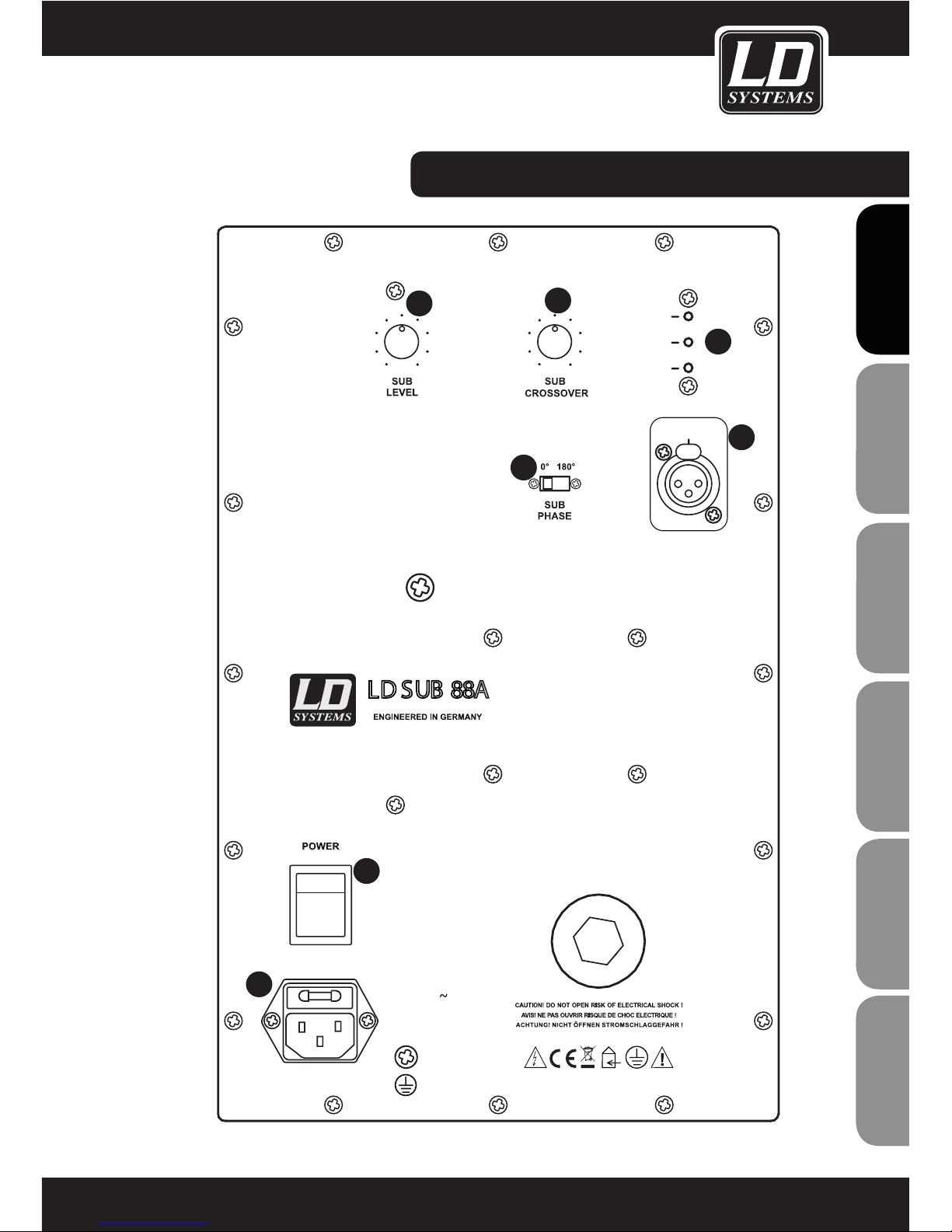
BACK PANEL ACTIVE SPEAKER:
LD SUB88A
1
POWER, SIGNAL, LIMIT LED POWER LED
Lights up green when device is turned to ON.
SIGNAL LED
Lights up green, when the unit receives an audio signal.
LIMIT LED
Lights up when loudspeaker is operated at its limit. Short-term blinking of the LED is not critical. If the limiter LED lights up longer than a brief moment or permanently (=over-driving the system), reduce the volume
of the connected signal source or the volume of the active loudspeaker cabinet. Non-compliance will lead to
unpleasant and distorted sound and may cause malfunction of the speaker system.
2
SUB CROSSOVER
Adjustable lowpass 80 - 200 Hz. Set the frequency to the lower cut off frequency of the connected satellites.
3
SUB LEVEL
Adjusts the volume of the active subwoofer.
4
INPUT XLR / 6.3 mm jack
Balanced Line Input for XLR
connectors and 6.3 mm jacks.
5
SUB PHASE
Inverts the phase of the subwoofer (0°/180°) if necessary.
6
POWER SWITCH
ON / OFF switch. Please switch connected devices to ON before switching the LD SUB88A to ON and to OFF
after switching the LD SUB88A to OFF.
7
POWER CONNECTION SEAT
Power connection seat 240 V (IEC power connector) and fuse seat. Replacement of fuse only if mains power
is disconnected and only by fuse of same type and rating (T1A 250V AC). If fuse blows repeatedly please
contact authorized personel for servicing.
ITALIANOPOLSKIESPAÑOL
FRANCAISFRANCAIS FRANCAISFRANCAIS
FRANCAISDEUTSCHENGLISH
13
INP UT
FU S E
T 2.0 AL 250 VAC
R E PL AC E
AS MA R KE D
220 -240V / 50- 60HZ
MAX 200 VA / AC
LI MIT
S IG NAL
P OW ER
MIN MAX 80 H z 200 H z
4
5
6
7
1
2
3
BACK PANEL ACTIVE SPEAKER:

ENGLISHDEUTSCHFRANCAIS
FRANCAISFRANCAIS FRANCAISFRANCAIS
ESPAÑOLPOLSKIITALIANO
14
BACK PANEL ACTIVE SPEAKER:
LD SUB10A
1
MAIN LEVEL
Preset of the main level of the system - subwoofer will be adjusted too, corresponding the preset of the SUB
LEVEL.
2
SUB PHASE
Phase invertation switch to invert the Phase of the Subwoofer (0° / 180°) if necessary due to an difficult
installation.
3
SUB LEVEL
Preset subwoofer level proportionally to the satellite level. We recommend at the standard setting 12:00
o‘clock.
4
LINE DIRECT OUTPUT (LEFT / RIGHT)
Direct symetrical Line Input for XLR connectors.
5
LINE INPUT
Symetrical Line Input for XLR connectors and 6.3 mm jacks.
6
SPEAKER OUTPUT (LEFT / RIGHT)
7
POWER CONNECTION SEAT
Power connection seat 240 V (IEC power connector) and fuse seat. Replacement of fuse only if power
connection is disconnected. If fuse blows repeatedly please contact authorized personel for servicing.
8
POWER SWITCH
ON / OFF switch. Please switch connected devices to ON first and to OFF after switching the system.

ITALIANOPOLSKIESPAÑOL
FRANCAISFRANCAIS FRANCAISFRANCAIS
FRANCAISDEUTSCHENGLISH
15
4
5
6
7
1
2
3
8
BACK PANEL ACTIVE SPEAKER:

ENGLISHDEUTSCHFRANCAIS
FRANCAISFRANCAIS FRANCAISFRANCAIS
ESPAÑOLPOLSKIITALIANO
16
4
5
6
7
1
2
3
8109
EXPLODED DRAWING BRACKET:
1
Wall mount panel
2
M6 bolt
3
U-Bracket
4
Washer
5
Wing nut M8
6
Rubber washer
7
Allen screw M6 x 16
8
Spring washer
9
Metal washer
10
LD SAT Cabinet

ITALIANOPOLSKIESPAÑOL
FRANCAISFRANCAIS FRANCAISFRANCAIS
FRANCAISDEUTSCHENGLISH
17
INSTALLATION COMBINATIONS:
LDSUB10A + 2 x 4 LDSAT42(W)

ENGLISHDEUTSCHFRANCAIS
FRANCAISFRANCAIS FRANCAISFRANCAIS
ESPAÑOLPOLSKIITALIANO
18
LDSUB10A + 2 x2 LDSAT62(W)
INSTALLATION COMBINATIONS:

ITALIANOPOLSKIESPAÑOL
FRANCAISFRANCAIS FRANCAISFRANCAIS
FRANCAISDEUTSCHENGLISH
19
LDSUB10A + 2 x2 LDSAT242(W)
INSTALLATION COMBINATIONS:
ENGLISHDEUTSCHFRANCAIS
FRANCAISFRANCAIS FRANCAISFRANCAIS
ESPAÑOLPOLSKIITALIANO
20
MANUFACTURER´S DECLARATIONS:
LIMITED WARRANTY
This Limited Warranty applies to the Adam Hall, LD Systems, LD Premium, Defender, Palmer, Cameo and Eminence
branded products.
The statutory warranty rights towards the seller are not affected by this guarantee. In fact, it justifies, additional
independent warranty claims towards Adam Hall.
Adam Hall warrants that the Adam Hall product you have purchased from Adam Hall or from an Adam Hall authorized reseller is free from defects in materials or workmanship under normal use for a period of 2 or 5 years from
the date of purchase.
The Limited Warranty Period starts on the date of purchase. In order to receive warranty services you are required
to provide proof of the purchase date. Your dated sales or delivery receipt, showing the date of purchase, is your
proof of the purchase date. Should products of the brands named above be in need of repair within the limited warranty period, you are entitled to warranty services according to the terms and conditions stated in this document.
This Limited Warranty extends only to the original purchaser of this Adam Hall branded product and is not transferable to anyone who obtains ownership of the Adam Hall branded product from the original purchaser. During
the Limited Warranty Period, Adam Hall will repair or replace the defective component parts or the product. All
component parts or hardware products removed under this Limited Warranty become the property of Adam Hall.
In the unlikely event that your Adam Hall product has a recurring failure, Adam Hall, at its discretion, may elect to
provide you with a replacement unit of Adam Hall´s choice that is at least equivalent to your Adam Hall branded
product in hardware performance.
Adam Hall does not warrant that the operation of this product will be uninterrupted or error-free. Adam Hall is not
responsible for damage that occurs as a result of your failure to follow the instructions included with the Adam
Hall branded product.
This Limited Warranty does not apply,
- to wear parts (e.g. accumulator)
- to any product from which the serial number has been removed or that has been damaged or rendered defective as the result of an accident
- in case of, misuse, abuse, or other external causes
- by operation outside the usage parameters stated in the user´s documentation shipped with the product by use
of spare parts not manufactured or sold by Adam Hall
- by modification or service by anyone other than Adam Hall
These terms and conditions constitute the complete and exclusive warranty agreement between you and Adam
Hall regarding the Adam Hall branded product you have purchased.

ITALIANOPOLSKIESPAÑOL
FRANCAISFRANCAIS FRANCAISFRANCAIS
FRANCAISDEUTSCHENGLISH
21
LIMITATION OF LIABILITY
If your Adam Hall branded hardware product fails to work as warranted above, your sole and exclusive remedy
shall be repair or replacement. Adam Halls’ maximum liability under this limited warranty is expressly limited
to the lesser of the price you have paid for the product or the cost of repair or replacement of any hardware
components that malfunction in conditions of normal use.
Adam Hall is not liable for any damages caused by the product or the failure of the product, including any lost
profits or savings or special, incidental, or consequential damages. Adam Hall is not liable for any claim made by
a third party or made by you for a third party.
This limitation of liability applies whether damages are sought, or claims are made, under this Limited Warranty
or as a tort claim (including negligence and strict product liability), a contract claim, or any other claim. This limitation of liability cannot be waived or amended by any person. This limitation of liability will be effective even if
you have advised Adam Hall of an authorized representative of Adam Hall of the possibility of any such damages.
This limitation of liability however, will not apply to claims for personal injury.
This Limited Warranty gives you specific legal rights. You may also have other rights that may vary from state to
state or from country to country. You are advised to consult applicable state or country laws for a full determination of your rights.
REQUESTING WARRANTY-SERVICE
To request warranty service for the product, contact Adam Hall or the Adam Hall authorized reseller from which
you purchased the product.
EC DECLARATION OF CONFORMITY
These devices meet the essential requirements and further relevant specifications of Directives 2004/108/EC
(EMC) and 2006/95/EC (LVD). For more information, see www.adamhall.com.
CORRECT DISPOSAL OF THIS PRODUCT (ELECTRICAL WASTE)
(Applicable in the European Union and other European countries with separate collection systems)
This marking shown on the product or its literature, indicates that it should not be disposed with other household
wastes at the end of its working life. To prevent possible harm to the environment or human health from uncontrolled waste disposal, please separate this from other types of wastes and recycle it responsibly to promote the
sustainable reuse of material resources.
Household users should contact either the retailer where they purchased this product, or their local government
office, for details on where and how they can recycle this item in an enviromentally friendly manner.
Business users should contact their supplier and check the terms and conditions of the purchase contract. This
product should not be mixed with other commercial wastes for disposal.

ENGLISHDEUTSCHFRANCAIS
FRANCAISFRANCAIS FRANCAISFRANCAIS
ESPAÑOLPOLSKIITALIANO
22
WEEE-DECLARATION
Your LD-Systems product was developed and manufactured with high quality materials and components wich
can be recycled and/or reused. This symbol indicates that electrical and electronic equipment must be disposed
of separately from normal waste at the end of its operational lifetime.
Please dispose of this product by bringing it to your local collection point or recycling centre for such equipment.
This will help to protect the environment in which we all live.
BATTERIES AND ACCUMULATORS
The supplied batteries or rechargeable batteries can be recycled. Please dispose of them as special waste or
return them to your specialist dealer. In order to protect the environment, only dispose exhausted batteries.
Adam Hall GmbH, all rights reserved. The technical data and the functional product characteristics can be subject
to modifications. The photocopying, the translation, and all other forms of copying of fragments or of the integrality of this user’s manual is prohibited.
MANUFACTURER´S DECLARATIONS:

ITALIANOPOLSKIESPAÑOL
FRANCAISFRANCAIS FRANCAISFRANCAIS
FRANCAISDEUTSCHENGLISH
23

ENGLISHDEUTSCHFRANCAIS
FRANCAISFRANCAIS FRANCAISFRANCAIS
ESPAÑOLPOLSKIITALIANO
24
Mit einem Produkt von LD Systems haben Sie die richtige Wahl getroffen!
Dieses Gerät wurde unter hohen Qualitätsanforderungen entwickelt und gefertigt, um viele Jahre einen
reibungslosen Betrieb zu gewährleisten. Dafür steht LD Systems mit seinem Namen und der langjährigen
Erfahrung als Hersteller hochwertiger Audioprodukte.
Bitte lesen Sie diese Bedienungsanleitung sorgfältig, damit Sie Ihr neues Produkt von LD Systems schnell
optimal einsetzen können.
Weitere Informationen zu Produkten von LD Systems erhalten Sie auf unserer Internet-Seite WWW.LD-SYSTEMS.COM.

ITALIANOPOLSKIESPAÑOL
FRANCAISFRANCAIS FRANCAISFRANCAIS
FRANCAISDEUTSCHENGLISH
25
LD SAT/SUB SERIES
INSTALLATIONS SPEAKER PASSIVE: SAT42 / SAT242 / SAT62 / SAT82 / SUB88
INSTALLATIONS SPEAKER ACTIVE: SAT62A / SUB10A / SUB88A

ENGLISHDEUTSCHFRANCAIS
FRANCAISFRANCAIS FRANCAISFRANCAIS
ESPAÑOLPOLSKIITALIANO
26
SICHERHEITSHINWEISE:
1. Lesen Sie diese Anleitung bitte sorgfältig durch.
2. Bewahren Sie alle Informationen und Anleitungen an einem sicheren Ort auf.
3. Befolgen Sie die Anweisungen.
4. Beachten Sie alle Warnhinweise.
5. Verwenden Sie das Gerät nur in der vorgesehenen Art und Weise.
6. Verwenden Sie ausschließlich stabile und passende Stative bzw. Befestigungen, wenn das Gerät fest installiert
wird. Stellen Sie sicher, dass Wandhalterungen ordnungsgemäß installiert und gesichert sind.
Stellen Sie sicher, dass das Gerät sicher installiert ist und nicht herunterfallen kann.
8. Betreiben Sie und installieren Sie das Gerät nicht in der Nähe von Heizkörpern, Wärmespeichern, Öfen oder
sonstigen Hitzequellen. Sorgen Sie dafür, dass das Gerät immer so installiert ist, dass es ausreichend gekühlt
wird und nicht überhitzt.
9. Platzieren Sie keine Zündquellen wie z. B brennende Kerzen auf dem Gerät.
10. Die Lüftungsschlitze dürfen nicht blockiert werden 11. Betreiben Sie das Gerät nicht in unmittelbarer Nähe
von Wasser.
12. Sorgen Sie dafür, dass kein Tropf- oder Spritzwasser in das Gerät eindringt. Platzieren Sie keine mit
Flüssigkeit gefüllten Behältnisse wie Vasen oder Trinkgefäße auf dem Gerät.
13. Sorgen Sie dafür, dass keine Gegenstände in das Gerät fallen können.
14. Betreiben Sie das Gerät nur mit dem vom Hersteller empfohlenen und vorgesehenen Zubehör.
15. ACHTUNG: Dieses Gerät der SCHUTZKLASSE I muss an einer Netzsteckdose mit Schutzleiter angeschlossen
werden. Deaktivieren Sie niemals den Schutzleiter des mitgelieferten Netzkabels.
Wenn das mitgelieferte Netzkabel nicht in Ihre Netzsteckdose passt, wenden Sie sich an einen Elektriker.
16. Treten Sie nicht auf das Netzkabel. Sorgen Sie dafür, dass das Netzkabel speziell an der Netz- und der
Gerätebuchse nicht geknickt wird.
17. Überprüfen Sie nach dem Anschluss des Geräts alle Kabelwege, um Schäden oder Unfälle, z.B. durch
Stolperfallen zu vermeiden.
18. Achten Sie bei der Verkabelung des Geräts immer darauf, dass das Netzkabel stets frei zugänglich ist.
19. Um das Gerät vollständig vom Stromnetz zu trennen, entfernen Sie das Netzkabel.
20. Wenn Ihr Gerät mit einem Volex-Netzanschluss bestückt ist, muss der passende Volex-Gerätestecker
entsperrt werden, bevor er entfernt werden kann. Das bedeutet aber auch, dass das Gerät durch eine Ziehen am
Netzkabel verrutschen kann, wodurch Personen verletzt werden und/oder andere Schäden auftreten können.
Verlegen Sie Ihre Kabel daher immer sorgfältig.
21. Entfernen Sie das Netzkabel bei Gefahr eines Blitzschlags oder wenn Sie das Gerät länger nicht verwenden.
22. Achten Sie während eines Transports darauf, dass das Equipment nicht herunterfallen kann, wodurch
Personen verletzt werden und/oder andere Schäden auftreten können.
23. Wenn Ihr Gerät nicht mehr ordnungsgemäß funktioniert, Flüssigkeiten oder Gegenstände in das Geräteinnere
gelangt sind oder das Gerät anderweitig beschädigt wurde, schalten Sie es sofort aus und entfernen Sie das
Netzkabel. Dieses Gerät darf nur von autorisiertem Fachpersonal repariert werden.
24. Verwenden Sie zur Reinigung des Geräts ein trockenes Tuch.
25. Beachten Sie alle in Ihrem Land geltenden Entsorgungsgesetze. Trennen Sie bei der Entsorgung bitte Plastik
und Papier bzw. Kartonagen voneinander.
26. Kunststoffbeutel müssen außer Reichweite von Kindern aufbewahrt werden.
ITALIANOPOLSKIESPAÑOL
FRANCAISFRANCAIS FRANCAISFRANCAIS
FRANCAISDEUTSCHENGLISH
27
CAUTION
RISK OF ELECTRIC SHOCK
DO NOT OPEN
ACHTUNg:
Entfernen Sie niemals die Abdeckung, da sonst das Risiko eines elektrischen Schlages besteht. Im Inneren
des Geräts befinden sich keine Teile, die vom Bediener repariert oder gewartet werden können. Lassen Sie
Reparaturen ausschließlich von qualifiziertem Service-Personal durchführen.
Das gleichschenkelige Dreieck mit dem Blitzsymbol kennzeichnet
nicht-isolierte, „gefährliche“ Spannungen im Gerät,
die einen für die Gesundheit gefährlichen Stromschlag verursachen können.
Das gleichschenkelige Dreieck mit dem Ausrufezeichen kennzeichnet wichtige Bedienungs- und
Wartungshinweise.
ACHTUNG! HOHE LAUTSTÄRKEN!
Dieses Gerät ist für den professionellen Einsatz vorgesehen. Der kommerzielle Betrieb dieses Geräts unterliegt
den jeweils gültigen nationalen Vorschriften und Richtlinien zur Unfallverhütung. Als Hersteller ist Adam Hall
gesetzlich verpflichtet, Sie ausdrücklich auf mögliche Gesundheitsrisiken hinzuweisen.
Gehörschäden und Dauerbelastung durch hohe Lautstärken: Dieser Lautsprecher kann hohe Schalldruckpegel
(SPL) erzeugen, die bei Künstlern, Mitarbeitern und Zuschauern zu irreparablen Gehörschäden führen können.
Vermeiden Sie länger anhaltende Belastung durch hohe Lautstärken über 90 dB.

ENGLISHDEUTSCHFRANCAIS
FRANCAISFRANCAIS FRANCAISFRANCAIS
ESPAÑOLPOLSKIITALIANO
28
PASSIVE LAUTSPRECHER
LD SAT42(W) / SAT242(W)
Pro Endstufenausgang können bis zu vier SAT42(W)- (bis zu zwei SAT242(W)-) Lautsprecher im Parallelbetrieb an 4
Ohm betrieben werden. Das Lautsprechersignal wird über das rückseitige Anschlussfeld einfach auf den nächsten
SAT42(W)- (SAT242(W)-) Lautsprecher durchgeschliffen.
LD SAT62(W)
Pro Endstufenausgang können bis zu vier SAT62(W)-Lautsprecher im Parallelbetrieb an 4 Ohm betrieben werden.
Das Lautsprechersignal wird über das rückseitige Anschlussfeld einfach auf den nächsten SAT62(W)-Lautsprecher
durchgeschliffen.
LD SAT82(W)
Pro Endstufenausgang können bis zu zwei SAT82(W)/ W-Lautsprecher im Parallelbetrieb an 4 Ohm betrieben werden.
Das Lautsprechersignal wird über das rückseitige Anschlussfeld einfach auf den nächsten SAT82(W) durchgeschliffen.
LD SUB88 in Verbindung mit dem LD SAT 42/242/62(W)
Verbinden Sie die Lautsprecherkabel von der Endstufe mit den Anschlüssen Input A und B des Subwoofers.
Anschließend verbinden Sie die Satelliten SAT42/242 oder SAT62 mit den Anschlüssen Output A und B. Bis zu vier
SAT42 / SAT62- oder bis zu zwei SAT242-Satelliten können in dieser Konfiguration an 4 Ohm betrieben werden. Wir
empfehlen Lautsprecherkabel wie das Adam Hall KLS 215 mit einem Leitungsquerschnitt von mindestens 2 x 1.5 mm².
HINwEISE zUM BETRIEB:
AKTIVLAUTSPRECHER
LD SAT62A
MONTAGE / INSTALLATION
Es wird empfohlen, das System immer als letztes ein- (ON) und als erstes auszuschalten (OFF), um die durch
angeschlossene Mischpulte etc. verursachten Einschaltgeräusche zu vermeiden. Wenn mehrere LD SAT62A
hintereinander geschaltet sind, sollten sie immer in der Anschlussreihenfolge ein- (ON) und in umgekehrter Reihenfolge
ausgeschaltet (OFF) werden. Im Betriebsmodus AUTO sollte die Audioquelle erst nach 10 Minuten ohne Signal
ausgeschaltet werden, um sicherzustellen, dass sich die angeschlossenen LD SAT62A im Standby-Modus befinden.
ANSCHLUSS UND BETRIEB
Schalten Sie den LD SAT62A aus (OFF), bevor Sie ihn anschließen. Der Anschluss kann sowohl über 6,3 mm
Klinkenstecker (symmetrisch dreipolig / unsymmetrisch zweipolig) als auch über symmetrische dreipolige XLR-Stecker
erfolgen. Nachdem Sie alle notwendigen Kabel angeschlossen und den Regler MAIN LEVEL ganz nach links gedreht
haben, können Sie die Audioquelle einschalten. Anschließend können Sie auch den LD SAT62A einschalten (ON) (siehe
oben). Drehen Sie jetzt den Regler MAIN LEVEL im Uhrzeigersinn, bis die gewünschte Lautstärke erreicht ist. Führen
Sie diese Schritte mit allen angeschlossenen LD SAT62A durch. Auf der Seite Rückseite Aktivlautsprecher finden
Sie eine Übersicht über die Bedien- und Anschlusselemente des LD SAT62A .
DURCHSCHLEIFEN DES SIGNALS
Bei den Systemen LD SAT62A lässt sich das Audiosignal mithilfe eines dreipoligen XLR-Kabels auf weitere Systeme
durchschleifen. Entsprechend ist es nicht notwendig, jedes Gerät einzeln mit der Audioquelle zu verbinden. Bitte
verwenden Sie dazu hochwertige XLR-Kabel und achten Sie auf eine sorgfältige Verkabelung.

ITALIANOPOLSKIESPAÑOL
FRANCAISFRANCAIS FRANCAISFRANCAIS
FRANCAISDEUTSCHENGLISH
29
SPEZIFIKATIONEN:
LD SAT42(W) LD SAT242(W) LD SAT62(W) LD SAT82(W) LD SAT62A
Product Installation speaker Installation speaker Installation speaker Installation speaker Installation speaker
Type passive passive passive passive active/bass reflex
Loudspeaker
4“ woofer & 1“ silkdome
tweeter
2 x 4“ woofer & 1“ silkdo-
me tweeter
6.5“ woofer & 1“
silkdome tweeter
8“ woofer & 1“ horn
tweeter
6.5” woofer & 1“
silkdome tweeter
Amplifier - - - - Class A/B
Dispersion 60° x 60° 60° x 60° 60° x 60° 60° x 60° 60° x 60°
Load capacity (RMS
/ max.)
60/100W 100/180W 80/130W 120/200W 50W
Frequency range 75Hz-20.000Hz 75Hz-20.000Hz 55Hz-20.000Hz 50Hz-20.000Hz 55Hz-20.000Hz
SPL 85 dB 88 dB 89 dB 93 dB 89 dB
Max. SPL 103 dB 108 dB 108 dB 114 dB 108 dB
Protection circuit - - - - excess current
Line in - - - -
sym. XLR / 6.3 mm
Jack
Line out - - - - sym. XLR
Power Input - - - - 220-240 V AC
Impedance 16ohms 8ohms 16ohms 8ohms -
Terminals Clamp-type connection Clamp-type connection Clamp-type connection Clamp-type connection -
Cabinet material 12 mm MDF 12 mm MDF 12 mm MDF 15 mm MDF 12 mm MDF
Cabinet surface textured paint textured paint textured paint textured paint textured paint
Dimension (WxHxD) 140 x 230 x 125 mm 140 x 378 x 135 mm 200 x 320 x 200 mm 247 x 410 x 243 mm 200 x 320 x 205 mm
Weight 2.7 kg 4.1 kg 4.1 kg 8.5 kg 6 kg
Accessories
4 M6 rigging/mounting
points, mounting brackets
4 M6 rigging/mounting
points, mounting brackets
4 M6 rigging/moun-
ting points, mounting
brackets
4 M6 rigging/mounting
points, mounting brackets
4 M6 rigging/moun-
ting points, mounting
brackets

ENGLISHDEUTSCHFRANCAIS
FRANCAISFRANCAIS FRANCAISFRANCAIS
ESPAÑOLPOLSKIITALIANO
30
RÜCKSEITE AKTIVLAUTSPRECHER:
1
MAIN LEVEL
Einstellen der Gesamtlautstärke
2
POWER MODE
Umschalten zwischen Dauerbetrieb (ON) und Standby-Modus (AUTO). In der Position AUTO schaltet sich
der Verstärker ein (ON), sobald ein Signal anliegt. Liegt mehrere Minuten lang kein Signal an, wechselt der
Verstärker wieder in den Standby-Modus.
3
POWER-LED
Die LED leuchtet ROT, wenn sich das Gerät im STANDBY-Modus befindet. Die LED leuchtet GRÜN, wenn
das Gerät eingeschaltet ist (ON).
4
INPUT XLR / 6,3 mm Klinke
Symmetrischer Line-Eingang für XLR-Stecker und 6,3 mm Klinkenstecker
5
LINE DIRECT AUSGANG
Symmetrischer Direct Out für XLR-Stecker. Zum Durchschleifen des Signals auf weitere LD SAT62A / LD
SAT82A.
6
NETZSCHALTER
AN/AUS-Schalter:
7
NETZBUCHSE
IEC-Netzbuchse, 240 V, mit integrierter Sicherung. Ziehen Sie vor dem Austausch der Sicherung das
Netzkabel und verwenden Sie nur Sicherungen vom gleichen Typ und mit identischen Werten (T1A
250V AC). Sollte die Sicherung wiederholt auslösen, wenden Sie sich bitte an einen qualifizierten
Servicetechniker.
8
OVERLOAD-LED
Leuchtet bei Überlastung des Lautsprechers. Reduzieren Sie sofort die Lautstärke.
LD SAT62A
 Loading...