

LD MEI1000-T, LD MEI1000 User Manual

POWER
PHONES
8
1 15
12
4
-20
-40dB 0dB
-10
-30
SET
INP UT LEVEL
R F
BATT
MEI1000-R
UHF Wireless Stereo BodyPack Receiver
LD MEI1000
WIRELESS IN EAR MONITORING SYSTEM
USER´S MANUAL
BEDIENUNGSANLEITUNG
MANUEL D`UTILISATION
MANUAL DE USUARIO
INSTRUKCJA OBSŁUGI

2
Thank you for choosing LD-Systems!
We have designed this product to give you reliable operation over many years. Therefore LD-Systems underwrites
high quality products with its name and many years of experience as a producer.
Please, take a few moments to read these instructions carefully, as we want you to enjoy your new LD-Systems
products quickly and to the fullest.
Further information about LD-Systems check our website WWW.LD-SYSTEMS.COM
ENGLISHDEUTSCHFRANCAIS
FRANCAISFRANCAIS FRANCAISFRANCAIS
ESPAÑOLPOLSKI

3
POWER
PHONES
8
1 15
12
4
-20
-40dB 0dB
-10
-30
SET
INPU T LEVEL
R F
BATT
MEI1000-R
UHF Wireless Stereo BodyPack Receiver
LD MEI1000
WIRELESS IN EAR MONITORING SYSTEM
ENGLISHDEUTSCHFRANCAIS
FRANCAISFRANCAIS FRANCAISFRANCAIS
ESPAÑOLPOLSKI

4
04
PREVENTIVE MEASURES:
1. Please read the attached safety instructions as well as the following instructions carefully.
2. Please keep all the instructions.
3. Please use the device only as intended.
4. Please respect the valid waste management rules. Please deliver the packaging divided into plastic and
paper/ cardboard to the recycling management.
5. Please refer all servicing to qualified personel only if the device is damaged, exposed to liquid/rain or if it does
not operate normally.
6. Please, do not expose to any kind of heat such as ovens, radiators, or any other devices (incl. amplifiers).
Please check for enough distance between amplifiers and walls, racks, etc. to prevent overheating.
7. After connection please check the wiring to prevent any kind of accident or damage.
Please never use any kind of damaged cable and wiring.
8. Only use authorized and stable stands, brackets, shelfs, tables etc.. for installations. Please check for
adequate stability against collapse.
9. Appearance of interferences when using wireless systems.
The simultaneous use of wireless microphones and of mobile phones (if both devices are not very distant from
each other) can lead to the appearance of interferences in the microphone signal which can be heard in the
PA system.
CAUTION:
To reduce the risk of electric shock, do not remove cover (or back). No user serviceable parts inside. Refer
servicing to qualified personnel.
The lightning flash with arrowhead symbol within an equilateral triangle is intended to alert the
user to the presence of uninsulated “dangerous voltage” within the product´s enclosure that may be
of sufficient magnitude to constitute a risk to persons.
The exclamation mark within an equilateral triangle is intended to alert the user to the presence of
important operating and maintenance (servicing) instructions in the literature accompanying the
appliance.
CAUTION! HIGH VOLUME!
You will operate this transmission system for professional use. Therefore the commercial use of this equipment
is liable to the rules and regulations of the Accident Prevention & Insurance Association of your industry sector.
Adam Hall as a manufacturer is bound to inform you formally about the existence of eventual sanitary risks.
This system is able to induce an acoustic pressure of 80 db. 85 db is by law the maximum audio pressure
level which your ear can be exposed to during a work day. It was set according to the technical expertise of the
occupational medicine as a basis for the noise rating level. Higher sound levels or longer exposition times could
damage your ear. The time of exposition by higher sound pressure levels should be shortened in order to prevent
from ear damages. Here are a few reliable warning signals which show that you have exposed yourself for a too
long period to excessive sound pressure levels:
- You hear bell- or whistling sounds!
- You have the impression that you can’t hear high tones anymore!
CA UTI ON
RIS K OF EL ECTRI C SHOC K
DO N OT OPE N
ENGLISHDEUTSCHFRANCAIS
FRANCAISFRANCAIS FRANCAISFRANCAIS
ESPAÑOLPOLSKI

5
SYSTEM PARTS:
POWER
PHONES
8
1 15
12
4
-20
-40dB 0dB
-10
-30
SET
INP UT LEVEL
MEI1000-T UH F PL L STE RE O TR ANS MI TT ER
Transmitter
Earphones
2“AA“ Batteries
R F
BATT
MEI1000-R
UHF Wireless Stereo BodyPack Receiver
Bodypack Receiver
Power Supply
Antenna
ENGLISHDEUTSCHFRANCAIS
FRANCAISFRANCAIS FRANCAISFRANCAIS
ESPAÑOLPOLSKI

6
LD MEI1000T TRANSMITTER FEATURES:
FRONT PANEL:
REAR PANEL:
POWER
PHONES
8
1 15
12
4
-20
-40dB 0dB
-10
-30
SET
INP UT LEVEL
ON/OFF Switch
Press and hold for two seconds to turn ON.
Press and hold to turn OFF.
Transmitter menu down button
Please see “SYSTEM SETUP” on page 8.
Transmitter menu up button
Please see “SYSTEM SETUP” on page 8.
Transmitter setup button
Please see “SYSTEM SETUP” on page 8.
DC adapter plug
Left track XLR input plug
Right track XLR input plug
LCD screen
Please see “SYSTEM SETUP” on page 8.
Input Level
Controls the input level.
Phones Output Control
Controls the earphone volume.
Earphones jack plug
PAD switch
Use to attennuate the input gain by 12dB.
To leave gain unaffected set the switch to 0dB.
Antenna plug
50
1
1
2
2
3
3
4
5
4
6
5
7
8
D.C. 12-18V IN
300mA
BALANCED
INPUTS
XLR
1 = SHIELD
2 = +
3 = -
TRS
T = +
R = S = SHIELD
PAD
-12 dB
0 dB
ANTENNA
0678
LEFT
RIGHT
ENGLISHDEUTSCHFRANCAIS
FRANCAISFRANCAIS FRANCAISFRANCAIS
ESPAÑOLPOLSKI
7
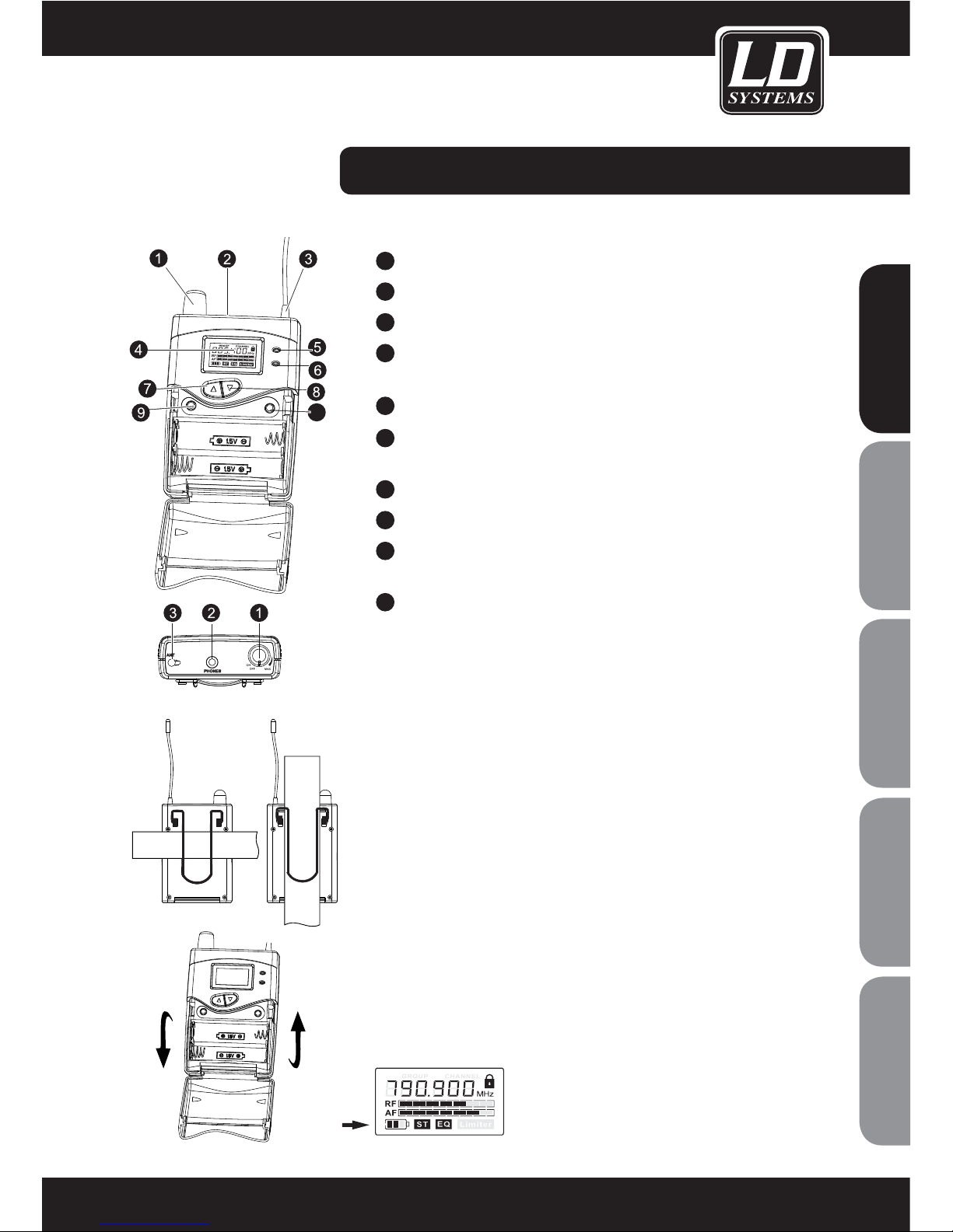
LD MEI1000BP BODYPACK FEATURES:
Earphone volume control and On/Off switch
Earphone plug
Antenna
LCD screen
Please see “SYSTEM SETUP” on page 10.
Low battery indicator
Power LED
Glows when device is turned on.
Receiver menu up button
Receiver menu down button
ESC button
Exits setup menu.
SET button
Use this to select setup parameters.
Wearing the Bodypack Receiver
Clip the receiver to a belt. For ultimate results, clip the receiver onto
a belt by pushing the receiver down onto the belt as far as it goes.
For guitarists, attach the guitar strap”through” the receiver clip.
SLIDE UNDER CLIP
WHEN MOUNTING
TO A BELT
Replacing the Batteries
The expected runtime for two alkaline batteries is approximately 10 hours
(depending on operating volume and battery model).
When the LCD panel battery sign flashes (see below) the batteries should
be replaced immediately.
1
2
3
4
10
5
6
7
8
9
10
ENGLISHDEUTSCHFRANCAIS
FRANCAISFRANCAIS FRANCAISFRANCAIS
ESPAÑOLPOLSKI

8
SYSTEM SETUP:
TRANSMITTER SETUP:
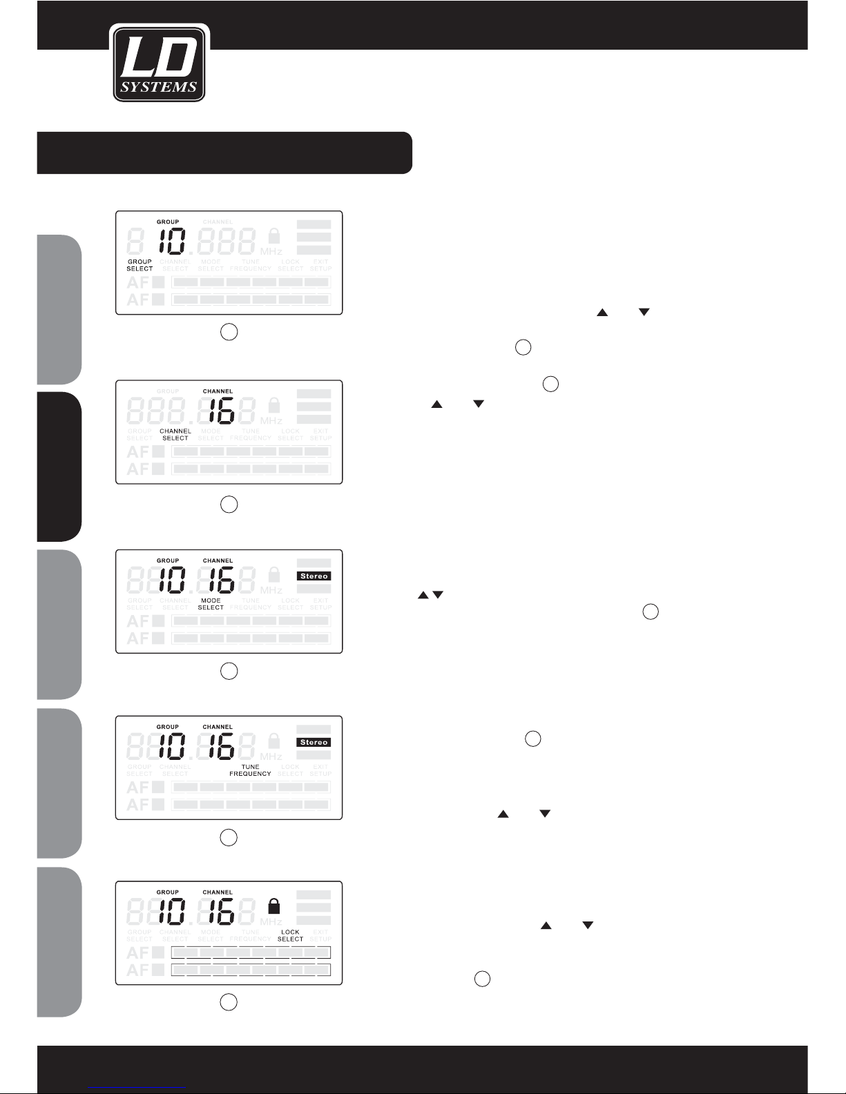
Select Group and Channel:
Repeatedly press the “SET” button until “GROUP SELECT” appears.
Press
or to select a suitable frequency group number, as
shown in diagram
1
on the left. Then press “SET” again until
“CHANNEL SELECT” appears, as shown in diagram 2 on the left.
Press
or to select a suitable channel.
Note:
When using multiple systems, for optimum result set all
of the systems to the same group number and select a different
channel number for each system in that group.
Working Mode Selection:
Repeatedly press the “SET” button until “MODE SELECT” appears,
press
or to select Stereo or Mono, as shown in diagram 3.
Tune frequency
Not applicable for MEI1000
4
.
To exit Setup:
Repeatedly press the “SET” button until “EXIT SETUP” appears.
Press
or to exit setup.
Locking Selection:
Repeatedly press the “SET” button until “LOCK SELECT” appears,
press
or to select lock or unlock, as shown in diagram 5.
When “LOCK SELECT” is activated settings in the transmitter can
be viewed but not changed.
1
2
4
3
5
ENGLISHDEUTSCHFRANCAIS
FRANCAISFRANCAIS FRANCAISFRANCAIS
ESPAÑOLPOLSKI
9
SYSTEM SETUP:
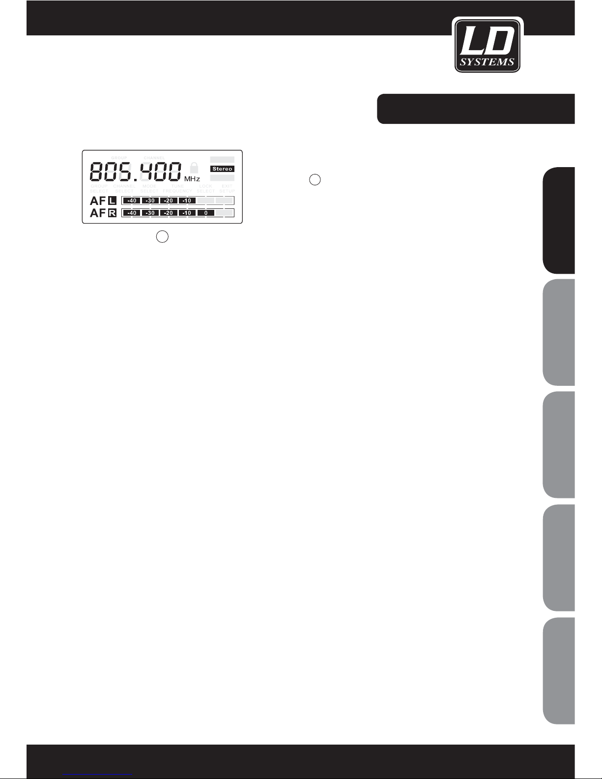
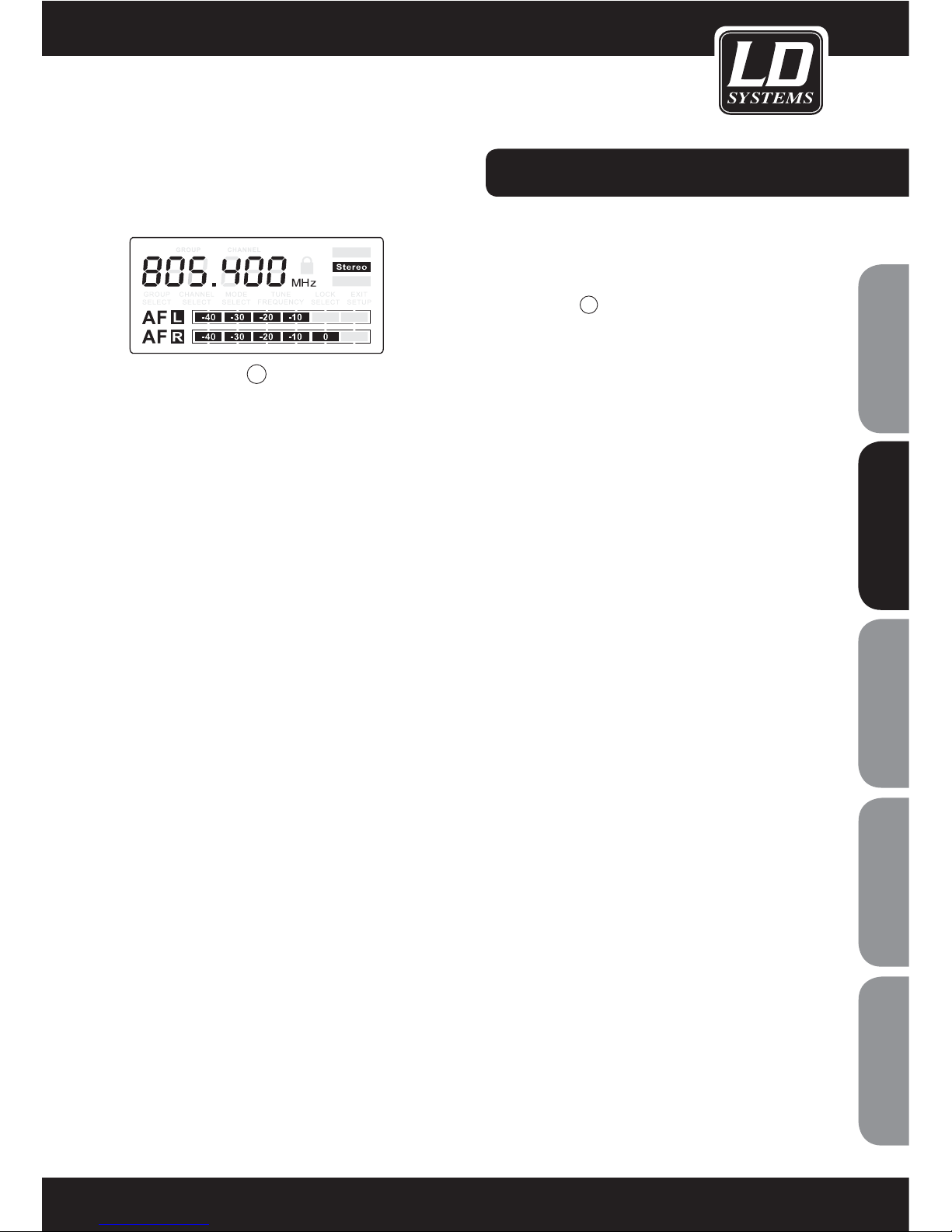
Audio Input Level Indication:
AF L and AF R display the left and right audio input level, as shown
in diagram
6
.
Note:
Adjust the audio input level using the „INPUT LEVEL “ control left
of the display.
6
ENGLISHDEUTSCHFRANCAIS
FRANCAISFRANCAIS FRANCAISFRANCAIS
ESPAÑOLPOLSKI
10
SYSTEM SETUP:
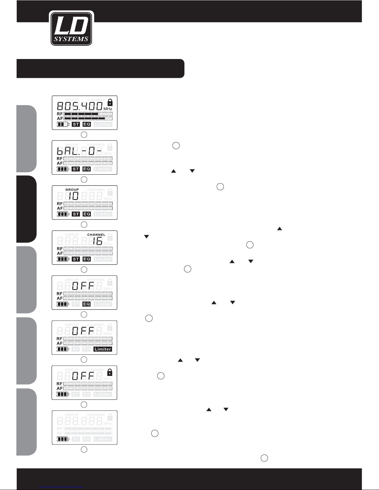
BODYPACK SETUP:
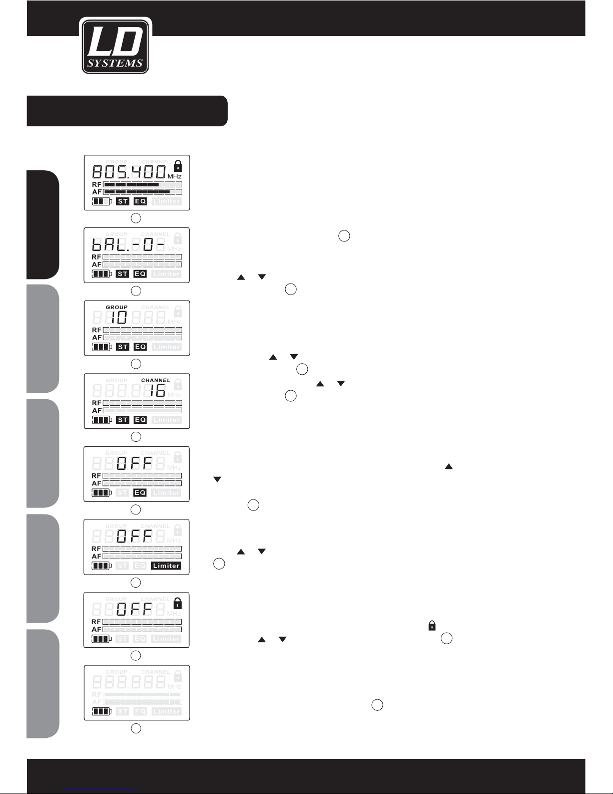
Full Display:
Displays battery status, RF/audio level, stereo/mono working
mode, EQ mode,locking status, limiter function and working
frequency, as shown in diagram
1
.
Left and Right Audio track Adjusting:
Press or to adjust left and right audio track balancing, as
shown in diagram
2
. Please see the chapter “THE FOCUS MODE“
for further information.
Select a Group and Channel:
Repeatedly press “SET” button, until “GROUP” appears and
flashes. Press
or to select suitable frequency group number,
as shown in diagram
3
on the left. Press “ SET” again until
“CHANNEL” flashes. Press or to select a suitable channel, as
shown in diagram
4
on the left.
Equalization setup:
Repeatedly press the “SET” button until “EQ” flashes. Press
or
to select the EQ working mode, Hight Boost (Offers more highend response: 6 dB boost at 10 kHz), Normal (Flat), as shown in
diagram
5
.
Limiter selection:
Repeatedly press the “SET” button until “LIMITER” flashes and
press
or to select the Limiter function, as shown in diagram
6
.
Locking selection:
Repeatedly press the “SET” button until “LOCK SELECT
”
flas-
hes
. Press or to lock or unlock, as shown in diagram 7.
When “LOCK SELECT” is activated settings in the transmitter can
be viewed but not changed.
Battery Indication:
The battery level is indicated in 4 stages
8
.
8
5
6
7
1
2
3
4
ENGLISHDEUTSCHFRANCAIS
FRANCAISFRANCAIS FRANCAISFRANCAIS
ESPAÑOLPOLSKI

11
SYSTEM SETUP:
FOCUS MODE
(ALSO KNOWN AS DOUBLE MONO MODE)
In the stereo mode (Focus mode off) 1, the two input signals can
be heard left and right over the receiver. On the receiver you can
adjust the balance between the input signals
2
.
In the Focus Mode (Focus mode on)
3
, both input signals are
mixed and can be heard in the centre over the receiver. You can
however adjust the mixing level between the two signals
4
.
One common application of this feature is that a musician can
adjust the mixing level between his instrument and the rest. Keep
in mind though that in this case, an additional aux send is required
on the mixer.
Note: This mode only works, when the transmitter is set to
stereo and if there is a signal present on both inputs.
Proceed as follows to activate or deactivate the Focus mode:
Turn on the receiver and repeatedly press the “SET” button until
the display shows “FO ON”
1
or “FO OFF” 3. You can now
change the mode by using the or button . Press “ESC” to
confirm and exit the menu.
You can now use the
or buttons to adjust the mixing level.
There are 15 Steps in each direction, the step range is as follows:
(-F, -E, -d, -C, -b, -A, -9, -8, -7, -6, -5, -4, -3, -2, -1, 0, 1, 2, 3, 4, 5,
6, 7, 8, 9, A, b, C, d, E, F). When set to 0, both signals can be heard
at equal levels.
3
4
1
2
ENGLISHDEUTSCHFRANCAIS
FRANCAISFRANCAIS FRANCAISFRANCAIS
ESPAÑOLPOLSKI
12
SPECIFICATIONS:
MEI 1000 T TRANSMITTER
Article No.: LDMEI1000T
Frequency range: 790.850 MHz - 813.800 MHz or
(838,850 – 861.800 MHz 144 Channels (9 Groups) + IEM-Band (863 – 865 MHz)
16 Channels (1 Group) X-Version)
Max channel number: 160
Switching bandwidth: 0.025 MHz
Modulation: FM
RF output power: 10 mW
Peak deviation: +/- 40 KHz
Frequency response: 60 - 16000 Hz
Signal-to-noise ratio: >102dB
THD: < 1 %
Input voltage range: 20 dBV max
Power supply: 12 - 18 V DC / 400 mA
Dimensions: 200 mm x 96 mm x 44 mm
Weight: 900 g
SYSTEM
Frequency range: 790.850 MHz - 813.800 MHz or
(838,850 – 861.800 MHz 144 Channels (9 Groups) + IEM-Band (863 – 865 MHz)
16 Channels (1 Group) X-Version)
Transmitter Output Level: 10 mW
Operating Range:
50 m (Note:actual range depends on RF signal absorption, reflection, and interference)
Audio Frequency Response (+/-3dB):
60 Hz - 16 kHz
THD: < 1 %
Dynamic Range: > 90 dB A-weighted
Operating Temperature Range: -10 C to +50 C (Note: battery characteristics may limit this range)
MEI 1000 BPR RECEIVER
Article No.: LDMEI1000BPR
Frequency range: 790.850 MHz - 813.800 MHz or
(838,850 – 861.800 MHz 144 Channels (9 Groups) + IEM-Band (863 – 865 MHz)
16 Channels (1 Group) X-Version)
Max channel number: 160
Switching bandwidth: 0.025 MHz
Modulation: wideband FM stereo
Stereo channel separetion: > 42 dB
Sensitivity: < - 94 dBm for 30 dB S/N Ratio
Peak deviation: +/- 40 KHz
Frequency response: 60 - 16000 Hz
Signal-to-noise ratio(stereo mode):
> 80 dB(A)
THD: < 1 %
Dynamic Range: > 95 dB
Headphone connector: 3.5 mm jack socket
Audio output level: 100 mW max
Power supply: 2 x 1.5 V (AA)
Battery life: > 13 h
Dimensions: 90 mm x 65 mm x 24 mm
Weight: 90 g
ENGLISHDEUTSCHFRANCAIS
FRANCAISFRANCAIS FRANCAISFRANCAIS
ESPAÑOLPOLSKI

13
ENGLISHDEUTSCHFRANCAIS
FRANCAISFRANCAIS FRANCAISFRANCAIS
ESPAÑOLPOLSKI

14
LIMITED WARRANTY
This Limited Warranty applies to the Adam Hall, LD Systems, Defender, Palmer and Eminence branded products.
The statutory warranty rights towards the seller are not affected by this guarantee. In fact, it justifies, additional
independent warranty claims towards Adam Hall.
Adam Hall warrants that the Adam Hall product you have purchased from Adam Hall or from an Adam Hall authorized reseller is free from defects in materials or workmanship under normal use for a period of 2 or 5 years from
the date of purchase.
The Limited Warranty Period starts on the date of purchase. In order to receive warranty services you are required
to provide proof of the purchase date. Your dated sales or delivery receipt, showing the date of purchase, is your
proof of the purchase date. Should products of the brands named above be in need of repair within the limited warranty period, you are entitled to warranty services according to the terms and conditions stated in this document.
This Limited Warranty extends only to the original purchaser of this Adam Hall branded product and is not transferable to anyone who obtains ownership of the Adam Hall branded product from the original purchaser. During the
Limited Warranty Period, Adam Hall will repair or replace the defective component parts or the product. All component parts or hardware products removed under this Limited Warranty become the property of Adam Hall.
In the unlikely event that your Adam Hall product has a recurring failure, Adam Hall, at its discretion, may elect to
provide you with a replacement unit of Adam Hall´s choice that is at least equivalent to your Adam Hall branded
product in hardware performance.
Adam Hall does not warrant that the operation of this product will be uninterrupted or error-free. Adam Hall is not
responsible for damage that occurs as a result of your failure to follow the instructions included with the Adam
Hall branded product.
This Limited Warranty does not apply,
- to wear parts (e.g. accumulator)
- to any product from which the serial number has been removed or that has been damaged or rendered defec
tive as the result of an accident
- in case of, misuse, abuse, or other external causes
- by operation outside the usage parameters stated in the user´s documentation shipped with the
product
- by use of spare parts not manufactured or sold by Adam Hall
- by modification or service by anyone other than Adam Hall
These terms and conditions constitute the complete and exclusive warranty agreement between you and Adam
Hall regarding the Adam Hall branded product you have purchased.
MANUFACTURER´S DECLARATIONS:
ENGLISHDEUTSCHFRANCAIS
FRANCAISFRANCAIS FRANCAISFRANCAIS
ESPAÑOLPOLSKI

15
LIMITATION OF LIABILITY
If your Adam Hall branded hardware product fails to work as warranted above, your sole and exclusive remedy
shall be repair or replacement. Adam Halls’ maximum liability under this limited warranty is expressly limited
to the lesser of the price you have paid for the product or the cost of repair or replacement of any hardware
components that malfunction in conditions of normal use.
Adam Hall is not liable for any damages caused by the product or the failure of the product, including any lost
profits or savings or special, incidental, or consequential damages. Adam Hall is not liable for any claim made by
a third party or made by you for a third party.
This limitation of liability applies whether damages are sought, or claims are made, under this Limited Warranty
or as a tort claim (including negligence and strict product liability), a contract claim, or any other claim. This limitation of liability cannot be waived or amended by any person. This limitation of liability will be effective even if
you have advised Adam Hall of an authorized representative of Adam Hall of the possibility of any such damages.
This limitation of liability however, will not apply to claims for personal injury.
This Limited Warranty gives you specific legal rights. You may also have other rights that may vary from state to
state or from country to country. You are advised to consult applicable state or country laws for a full determination of your rights.
REQUESTING WARRANTY-SERVICE
To request warranty service for the product, contact Adam Hall or the Adam Hall authorized reseller from which
you purchased the product.
EC DECLARATION OF CONFORMITY
These devices meet the essential requirements and further relevant specifications of Directives 1999/5/EC (R &
TTE), 2004/108/EC (EMC) and 2006/95/EC (LVD). For more information, see www.adamhall.com.
CORRECT DISPOSAL OF THIS PRODUCT (ELECTRICAL WASTE)
(Applicable in the European Union and other European countries with separate collection systems)
This marking shown on the product or its literature, indicates that it should not be disposed with other household
wastes at the end of its working life. To prevent possible harm to the environment or human health from uncontrolled waste disposal, please separate this from other types of wastes and recycle it responsibly to promote the
sustainable reuse of material resources.
Household users should contact either the retailer where they purchased this product, or their local government
office, for details on where and how they can recycle this item in an enviromentally friendly manner.
Business users should contact their supplier and check the terms and conditions of the purchase contract. This
product should not be mixed with other commercial wastes for disposal
ENGLISHDEUTSCHFRANCAIS
FRANCAISFRANCAIS FRANCAISFRANCAIS
ESPAÑOLPOLSKI

16
WEEE-DECLARATION
Your LD-Systems product was developed and manufactured with high quality materials and components wich
can be recycled and/or reused. This symbol indicates that electrical and electronic equipment must be disposed
of separately from normal waste at the end of its operational lifetime.
Please dispose of this product by bringing it to your local collection point or recycling centre for such equipment.
This will help to protect the environment in which we all live.
BATTERIES AND ACCUMULATORS
The supplied batteries or rechargeable batteries can be recycled. Please dispose of them as special waste or return
them to your specialist dealer. In order to protect the environment, only dispose exhausted batteries.
Adam Hall GmbH, all rights reserved. The technical data and the functional product characteristics can be subject
to modifications. The photocopying, the translation, and all other forms of copying of fragments or of the integrality of this user’s manual is prohibited.
ENGLISHDEUTSCHFRANCAIS
FRANCAISFRANCAIS FRANCAISFRANCAIS
ESPAÑOLPOLSKI

17
NOTES:
ENGLISHDEUTSCHFRANCAIS
FRANCAISFRANCAIS FRANCAISFRANCAIS
ESPAÑOLPOLSKI

18
Sie haben die richtige Wahl getroffen!
Diese LD-Systems Produkte werden Sie lange Jahre durch Zuverlässigkeit, Wirtschaftlichkeit und einfaches
Handling überzeugen. Dafür garantiert LD-Systems mit seinem Namen und seiner in vielen Jahren erworbenen
Kompetenz als Hersteller hochwertiger Geräte.
Nehmen Sie sich nun ein paar Minuten Zeit, diese Anleitung zu lesen. Wir möchten, dass Sie einfach
und schnell in den Genuss dieser Technik kommen.
Mehr Informationen zu LD-SYSTEMS finden Sie auf unserer Internetseite WWW.LD-SYSTEMS.COM
ENGLISHDEUTSCHFRANCAIS
FRANCAISFRANCAIS FRANCAISFRANCAIS
ESPAÑOLPOLSKI

19
POWER
PHONES
8
1 15
12
4
-20
-40dB 0dB
-10
-30
SET
INPU T LEVEL
R F
BATT
MEI1000-R
UHF Wireless Stereo BodyPack Receiver
LD MEI1000
WIRELESS IN EAR MONITORING SYSTEM
ENGLISHDEUTSCHFRANCAIS
FRANCAISFRANCAIS FRANCAISFRANCAIS
ESPAÑOLPOLSKI
20
20
1. Bitte beachten Sie die Sicherheitshinweise und studieren Sie diese Anleitung sorgfältig.
2. Bewahren Sie alle Hinweise und Anleitungen sicher auf.
3. Verwenden Sie das Gerät nur in der vorgesehenen Art und Weise.
4. Beachten die in Ihrem Land geltenden Entsorgungsgesetze. Trennen Sie bei der Entsorgung bitte Plastik und
Papier bzw. Kartonagen von einander.
5. Sollte Ihr Gerät nicht mehr ordnungsgemäß funktionieren, Flüssigkeiten ausgesetzt werden oder auf sonstige Art
und Weise beschädigt sein, überlassen Sie bitte jegliche Reparaturen ausschließlich autorisiertem Fachpersonal.
6. Halten Sie das Gerät von Hitzequellen wie z.B. Ofen, Heizkörper, oder sonstige Quellen (auch Verstärker) fern.
Sorgen Sie dafür dass das Gerät immer so installiert ist, dass es ausreichend gekühlt wird und nicht überhitzt.
7. Überprüfen Sie alle Verbindungen nach dem Sie das Gerät angeschossen haben um Schäden oder Unfälle zu
vermeiden.
8. Verwenden Sie ausschließlich stabile und passende Stative bzw. Befestigungen wenn das Gerät fest installiert
wird. Stellen Sie sicher, dass das Gerät sicher installiert ist und nicht herunterfallen kann.
9. Auftretende Störungen beim Betrieb von Wireless Systemen.
Beim gleichzeitigen Betrieb von Funkmikrofonen und Funktelefonen (bei geringer Entfernung der Geräte zu
einander) können im Bereich der Funkmikrofone Störungen auftreten, welche im angeschlossenen
Audiosystem hörbar sind.
ACHTUNG:
Entfernen Sie niemals die Abdeckung, da sonst die Gefahr eines elektrischen Schocks besteht.
Im Inneren des Gerätes befinden sich keine Teile, die vom Bediener gewartet oder repariert werden können.
Lassen Sie Reparaturen ausschließlich von qualifiziertem Servicepersonal durchführen.
Dieses Symbol warnt vor nichtisolierten, gefährlichen Spannungen im Geräteinneren,
die einen gefährlichen Schlag verursachen können.
Dieses Symbol kennzeichnet wichtige Bedienungs- und Wartungshinweise.
Vorsicht! Hohe Lautstärke!
Diese Übertragungsanlage wird von Ihnen professionell eingesetzt. Daher unterliegt der Gebrauch bei gewerblicher Nutzung den Regeln und Vorschriften der zuständigen Berufsgenossenschaft. Adam Hall als Hersteller ist
daher verpflichtet, Sie auf möglicherweise bestehende gesundheitliche Risiken ausdrücklich hinzuweisen.
Mit diesem System können Schalldrücke über 80 db erzeugt werden. 85db ist der Schalldruck, der laut Gesetz
als maximal zulässiger Wert über die Dauer eines Arbeitstages auf Ihr Gehör einwirken darf. Er wird nach den
Erkenntnissen der Arbeitsmedizin als Berurteilungspegel zu Grunde gelegt. Höhere Lautstärken oder längere
Einwirkzeit können Ihr Gehör schädigen. Bei höheren Lautstärken muss die Hörzeit verkürzt werden, um eine
Schädigung auszuschließen. Sichere Warnsignale dafür, dass Sie sich zu lange zu lautem Geräusch ausgesetzt
haben, sind:
- Sie hören Klingel- oder Pfeifgeräusche in den Ohren!
- Sie haben den Eindruck, hohe Töne nicht mehr wahrzunehmen!
VORSICHTSMASSNAHMEN:
CA UT IO N
RIS K OF ELE CTRI C SHOC K
DO NO T OPEN
ENGLISHDEUTSCHFRANCAIS
FRANCAISFRANCAIS FRANCAISFRANCAIS
ESPAÑOLPOLSKI

21
SYSTEMKOMPONENTEN:
POWER
PHONES
8
1 15
12
4
-20
-40dB 0dB
-10
-30
SET
INP UT LEVEL
MEI1000-T UH F PL L STE RE O TR ANS MI TT ER
Sender
Ohrhöhrer
2“AA“ Batterien
R F
BATT
MEI1000-R
UHF Wireless Stereo BodyPack Receiver
Bodypack Empfänger
Netzteil
Antenne
ENGLISHDEUTSCHFRANCAIS
FRANCAISFRANCAIS FRANCAISFRANCAIS
ESPAÑOLPOLSKI

22
LD MEI1000T SENDERFUNKTIONEN:
VORDERSEITE:
RÜCKSEITE:
POWER
PHONES
8
1 15
12
4
-20
-40dB 0dB
-10
-30
SET
INP UT LEVEL
AN/AUS Taste
Drücken und halten Sie diese Taste für 2
Sekunden, um das Gerät anzuschalten.
Drücken und halten Sie ebenfalls die Taste 2
Sekunden um das Gerät auszuschalten.
Sender Menü „nach unten“ Taste
Sehen Sie bitte „Systemeinstellungen“ auf S.24.
Sender Menü „nach oben“ Taste
Sehen Sie bitte „Systemeinstellungen“ auf S.24.
Sender Setup Taste
Sehen Sie bitte „Systemeinstellungen“ auf S.24.
DC Netzteilanschluss
XLR Eingang des linken Kanals
XLR Eingang des rechten Kanals
LCD Anzeige
Sehen Sie bitte „Systemeinstellungen“ auf S.24.
Eingangspegelregler
Lautstärkeregelung Kopfhöhrerausgang
Kopfhöhrerausgang
PAD Schalter
Schalter um die Eingänge um bis zu 12dB zu dämpfen.
In der 0dB Stellung, findet keine Dämpfung der Eingänge statt.
Antennenanschluss
50
1
1
2
2
3
3
4
5
4
6
5
7
8
D.C. 12-18V IN
300mA
BALANCED
INPUTS
XLR
1 = SHIELD
2 = +
3 = -
TRS
T = +
R = S = SHIELD
PAD
-12 dB
0 dB
ANTENNA
0678
LEFT
RIGHT
ENGLISHDEUTSCHFRANCAIS
FRANCAISFRANCAIS FRANCAISFRANCAIS
ESPAÑOLPOLSKI

23
LD MEI1000BP EMPFÄNGERFUNKTIONEN:
Lautstärkeregler für den Ohrhöhrer, sowie AN/AUS Schalter
Kopfhöhreranschluss
Antenne
LCD Anzeige
Sehen Sie bitte „Systemeinstellungen“ auf Seite 26.
Batteriestandsanzeige
Leuchtet auf, wenn der Batteriestand niedrig ist.
Power LED
Leuchtet auf, wenn das Gerät eingeschaltet ist.
Menütaste „nach oben“
Menütaste „nach unten“
ESC Taste
Zum verlassen des Einstellungsmenüs.
SET Taste
Mit dieser Taste können Sie zwischen den verschiedenen Einstellungsmöglichkeiten schalten.
Tragen des Bodypack Empfängers
Befestigen Sie den Empfänger mit dem Bügel an einen Gürtel bzw.
Gitarrengurt. Für den optimalen Sitz des Empfängers am Gürtel sollte der
Empfänger stets vollständig auf den Gürtel aufgeschoben werden.
Clip hinter den
Gürtel schieben
Ersetzen der Batterien
Die durchschnittliche Betriebsdauer zweier Alkaline-Batterien beträgt
je nach Lautstärke und Batteriemodel ca. 10 Stunden im Dauerbetrieb,
abhängig vom Fabrikat. Wenn die LED für den niedrigen Batteriestand
aufleuchtet, sollten die Batterien umgehend gewechselt werden.
1
2
3
4
10
5
6
7
8
9
10
ENGLISHDEUTSCHFRANCAIS
FRANCAISFRANCAIS FRANCAISFRANCAIS
ESPAÑOLPOLSKI
24
SYSTEMEINSTELLUNGEN:
SENDEREINSTELLUNGEN:
Auswählen einer Gruppe und eines Kanals:
Drücken sie die „SET“ Taste so oft, bis „GROUP SELECT“ im
Display erscheint. Drücken Sie die Tasten
oder um eine
passende Frequenzgruppe auszuwählen, sehen Sie dazu die
nebenstehende Abbildung
1
. Drücken Sie nun wiederholt die
„SET“ Taste bis „CHANNEL SELECT“ im Display erscheint wie in
der nebenstehenden Abbildung
2
zu sehen ist. Drücken Sie nun
die Tasten oder um einen passenden Kanal auszuwählen.
Hinweis:
Wenn Sie mehrere Systeme gleichzeitig verwenden, sollten Sie
für beste Ergebnisse an allen Systemen dieselbe Gruppe aber
unterschiedliche Kanäle einstellen.
Auswahl des Arbeitsmodus:
Drücken Sie die „SET“ Taste so oft, bis „MODE SELECT“ erscheint.
Mit den
Tasten können Sie zwischen Stereo und Mono wäh-
len. Sehen Sie dazu die nebenstehende Abbildung 3.
Tune frequency
Ohne Funktion bei MEI1000
4
.
Verlassen des Setup-Menüs
Drücken Sie die „SET“ Taste so oft, bis „EXIT SETUP“ im Display
erscheint. Drücken Sie
oder um das Menü zu verlassen.
Verriegelung des Systems:
Drücken Sie die „SET“ Taste so oft, bis „LOCK SELECT“ im Display
erscheint. Drücken Sie nun die
oder Tasten um das System
zu verriegeln bzw. freizugeben. Wenn „LOCK SELECT“ aktiviert
ist, können die Einstellungen im System betrachtet aber nicht
verändert werden.
5
1
2
4
3
5
ENGLISHDEUTSCHFRANCAIS
FRANCAISFRANCAIS FRANCAISFRANCAIS
ESPAÑOLPOLSKI
25
SYSTEMEINSTELLUNGEN:
Eingangspegelanzeige:
Die beiden Balken AF L und AF R im Display zeigen die Eingangspegel der beiden Eingangssignale an. Sehen Sie dazu die
nebenstehende Abbildung
6
.
Hinweis:
Regeln Sie den Eingangspegel über den Pegelsteller links des
Displays.
6
ENGLISHDEUTSCHFRANCAIS
FRANCAISFRANCAIS FRANCAISFRANCAIS
ESPAÑOLPOLSKI
26
SYSTEMEINSTELLUNGEN:
BODYPACKEINSTELLUNGEN:
Das Display:
Das Display zeigt folgendes an: Batteriestand, RF/AF Pegel, Stereo/
Mono Modus, EQ, Verriegelungsstatus, Limiter sowie die eingestellte Frequenz.
1
Einstellen des Links/Rechts Verhältnisses (Balance)
Drücken Sie die oder Tasten um die Balance zwischen
dem linken und dem rechten Audiokanal einzustellen, sehen Sie
dazu die nebenstehende Abbildung
2
. Im Kapitel „DER FOCUS
MODUS“ erfahren Sie mehr zu diesem Thema.
Auswählen einer Gruppe und eines Kanals:
Drücken Sie die „SET“ Taste am Empfänger so oft bis die Anzeige
„GROUP“ erscheint und zu blinken beginnt. Drücken Sie nun
oder um eine entsprechende Frequenzgruppe auszuwählen
(sehen Sie hierzu die nebenstehende Abbildung
3
). Drücken Sie
nun die „SET“ Taste bis „CHANNEL“ im Display erscheint und
blinkt und wählen Sie auch hier über die
oder Tasten einen
passenden Kanal aus
4
.
EQ Einstellung:
Drücken Sie die „SET“ Taste so oft, bis „EQ“ im Display erscheint
und blinkt. Drücken Sie die Taste
oder um den Arbeitsmodus
des EQs einzustellen. Sehen Sie hierzu die nebenstehende Abbildung
5
. Bei eingeschaltetem EQ werden die Höhen ab 10kHz um
6dB angehoben.
Limiter Einstellung:
Drücken Sie die „SET“ Taste bis „LIMITER“ im Display erscheint
und blinkt. Mit den
und Tasten können Sie den Limiter
aktivieren bzw. deaktivieren. Sehen Sie hierzu die nebenstehende
Abbildung
6
.
Verriegelung des Systems
Drücken Sie die „SET“ Taste so oft, bis das Schloss im Display
erscheint. Drücken Sie nun die
und Tasten um das System zu
verriegeln bzw. freizugeben. Wenn das System verriegelt ist, können die Einstellungen im System betrachtet aber nicht verändert
werden
7
.
Batteriestandsanzeige:
Der Stand der Batterie wird in 4 vier Stufen angezeigt 8.
8
5
6
7
1
2
3
4
ENGLISHDEUTSCHFRANCAIS
FRANCAISFRANCAIS FRANCAISFRANCAIS
ESPAÑOLPOLSKI
 Loading...