

Page 1

www.hrcctv.com
DIGITAL VIDEO RECORDER
USER MANUAL
LCTVR6104
LCTVR8208
LCTVR8216
Page 2
USER MANUAL
LCTVR6104-8208-8216
pag.
2
www.hrcctv.com
NORME GENERALI DI SICUREZZA -
General safety recommendations
Sicurezza delle persone - Safety warnings
Leggere e seguire le istruzioni - Tutte le
istruzioni per la sicurezza e per l'operatività
devono essere lette e seguite prima che il
prodotto sia messo in funzione.
Precauzioni particolari - Rispettare
tassativamente l'ordine delle istruzioni di
installazione e collegamento descritte nel
manuale. Verificare le indicazioni riportate sulla targa di
identificazione: esse devono corrispondere alla vostra rete
elettrica di alimentazione ed al consumo elettrico. Conservate le
istruzioni per una consulta futura.
Read and follow the instructions - Read the installation
instructions before connecting the system to its power source.
Follow these guidelines to ensure general safety.
In order to prevent injury, burns or electrical shock to yourself
and others, follow the connection instruction plan carefully.
Sicurezza del prodotto - Product Safety
Non posizionare in prossimità di liquidi oppure in un ambiente ad
umidità eccessiva.
Non lasciare penetrare del liquido o corpi estranei all'interno
dell'apparecchiatura.
Non ostruire le griglie di aerazione.
Non sottoporre all'esposizione dei raggi solari oppure in prossimità
di fonti di calore.
Do not use the product in a wet location.
Never push a foreign object through an opening inside the
product.
Slots and openings are provided for ventilation and should never
be covered.
Do not place under direct sunlight or heat sources.
INFORMAZIONI SULL’AMBIENTE ENVIRONMENT INFORMATION
Note per lo smaltimento del prodotto
valide per la Comunità Europea
Questo prodotto è stato progettato e
assemblato con materiali e componenti
di alta qualità che possono essere
riciclati e riutilizzati. Non smaltire il
prodotto come rifiuto solido urbano ma
smaltirlo negli appositi centri di
raccolta. E’ possibile smaltire il
prodotto direttamente dal distributore
dietro l’acquisto di uno nuovo,
equivalente a quello da smaltire. Abbandonando il prodotto
nell’ambiente si potrebbero creare gravi danni all’ambiente
stesso. Nel caso il prodotto contenga delle batterie è
necessario rimuoverle prima di procedere allo smaltimento.
Queste ultime debbono essere smaltite separatamente in
altri contenitori in quanto contenenti sostanze altamente
tossiche.
Il simbolo rappresentato in figura rappresenta il bidone dei
rifiuti urbani ed è tassativamente vietato riporre
l’apparecchio in questi contenitori.
L’immissione sul mercato dopo il 1° luglio 2006 di prodotti
non conformi al DLgs 151 del 25-07-05 (Direttiva RoHS
RAEE) è amministrativamente sanzionato.
Disposal of waste products for European Union
This products was designed to minimize their impact on the
environment by reducing or eliminating hazardous
materials and designing for recyclables.
This product should be handed over to a designated
collection point, e.g., on an authorized one -for-one basis
when you buy a new similar product or to an authorized
collection site for recycling waste electrical and electronic
equipment. Improper handling of this kind of waste could
have a possible negative impact on the environment and
human health due to potentially hazardous substances.
This symbol indicates that this product has not to be
disposed of with your household waste, according to the
WEEE Directive.
For more information about where you can drop off your
waste equipment for recycling, please contact your local
city waste authority, or your household waste disposal
service.
GARANZIA - Warranty
Questa garanzia ha validità di 2 anni a partire dalla data
di acquisto assicurata solo dietro presentazione della
fattura o scontrino rilasciati al cliente dal rivenditore.
L’assistenza gratuita non è prevista per i guasti causati da:
-Uso improprio del prodotto, immagazzinamento
inadeguato, cadute o urti, usura, sporcizia, acqua, sabbia,
manomissione da personale non autorizzato del prodotto
rispetto a quanto previsto nei manuali d’uso inclusi.
-Riparazioni, modifiche o pulizia effettuate da centri
assistenza non autorizzati da HR EUROPE.
-Danni o incidenti le cui cause non possono essere attribuite
alla HR EUROPE, comprendenti e non limitati a fulmini,
eventi naturali, alimentazione e ventilazione inadeguata.
This warranty is valid for 2 years from the date of
purchase obtained only against presentation of the
original invoice/ cash ticket issued to the customer by
the retailer.
Warranty repair service is excluded if damage or defects
have been caused by:
-Improper use, incorrect storage, dropping or shocks,
corrosion, dirt, water, handing or operation of the product
as referred to in the users’ manuals.
Page 3

USER MANUAL
LCTVR6104-8208-8216
www.hrcctv.com pag.3
SUMMARY
1.
INTRODUCTION................................................................................................................. 4
warnings and cautions.............................................................................................. 4
package contents .................................................................................................... 4
CD-ROM software .................................................................................................... 4
Technical feature................................................................................................... 5
2.
INSTALLATION .................................................................................................................. 6
Rear panel other view and connection ........................................................................ 6
2.2 head-on panel ................................................................................................... 10
2.3 remote control .................................................................................................. 13
2.4 HD Installation ............................................................................................. 15
2.4.1 Hard Disk select......................................................................................................................15
2.4.2 Hard Disk estimate size..............................................................................................................15
2.4.3 Hard Disk assembling ................................................................................................................15
3.
SETUP MENU.................................................................................................................. 16
3.1 Main menu..................................................................................................... 16
3.2 system Setup .................................................................................................... 16
3.3 CAMERA setup ................................................................................................ 17
3.4 RECORD SET.................................................................................................... 17
3.5 SCHEDULE SET.................................................................................................. 17
3.6 MOtION SET ..................................................................................................... 18
3.7 PTZ SET .......................................................................................................... 18
3.8 netWORK SET .................................................................................................. 18
3.9 SPOT (only 8 and 16 channel) ............................................................................... 18
3.10 DVD-CD/RW Backup( 8 AND 16 cHANNEL) ............................................................... 19
3.11 DISK manage................................................................................................. 19
3.12 LOG search .................................................................................................. 19
4 BASE PLANNING .................................................................................................................... 20
4.1 MANUAL recording ............................................................................................ 20
4.2 planned recording ............................................................................................. 20
4.3 SEARCH ........................................................................................................... 20
4.3.1 search time and BACKUP USB ....................................................................................................21
4.3.2 Record search and BACKUP USB ...............................................................................................21
4.3.3 event record search and BACKUP USB ..........................................................................................21
5 NETWORK CONNECTION ....................................................................................................... 22
5.1 IP address configuration ...................................................................................... 22
5.2 connection by Internet Explorer............................................................................ 22
5.3 Software anvplayer through connection............................................................... 26
5.4 SMART PHONE by means of connection ................................................................... 29
the least system required:......................................................................................................29
Installation:.......................................................................................................................29
Page 4

USER MANUAL
LCTVR6104-8208-8216
pag.
4
www.hrcctv.com
1. INTRODUCTION
Warnings and cautions
Do not expose this product to rain or moisture
Take away from clammy
Put in horizontal position
Skip out to the violent vibration
Do not rest up on another electric device
Exposition at light air,,do not cooling off the rear of DVR.
Package contents
Control the next accessory:
1. one power cable of 230 Vac.
2 .one power adequate 12Vdc.
3. one user manual
4. one CD software put in
5. one remote control of piloting to distant (with two battery powered 1.5V).
6. one set of screw
CD-ROM software
The content of the CD dowry:
Software cliente by faraway connexion by net LAN/WAN
Software Cliente for smarphone
User manual LCTVRxxxx_V_1_0.pdf
Page 5

USER MANUAL
LCTVR6104-8208-8216
www.hrcctv.com pag.5
Technical features
model
LCTVR6104 LCTVR8208 LCTVR8216
System
Operating system
Embedded Operating System
Control device
Frontal panel , remote control
Video
Video input (PAL) BNC_1.0VP- P_ 75Ω
4
8 16
Video output 1 channel PAL, BNC1.0VP- P 75Ω ) 1 channel VGA (800x600 60Hz)
SPOT out
NO 1 1
Picture resolution Real time display: PAL 704×576 Recording : D1: 704 * 576
CIF 352×288
Recording fram rate
Real Time
CIF:25 fps for channel
CIF:12 fps for channel
Video compressing
MPEG4 H.264
Video display
1 o 4 window
1, 4, 8 window 1,4,8, 16 window
Video standard
PAL
Picture quality
3 level
Camera adjustment
brightness, hue , contrast , saturation
Video information
channel, Date and hour, Video Loss, Recording ON
Motion and alarm
Motion detection
Zones: 192 (16*12) detection zones
sensitivity : high – Normal – low
Velocity: , high – Normal –low
Alarm input
4 input NA 8 input NA 16 input NA
Alarm output
1 relay output NA/NC/COM
Hard Disk
Hard disk lodging
2 HD IDE (no including) 2 HD Sata (no including)
Hard disk space occupation
(Resolution CIF - 25 fps – normal quality):
~
800MB/H
~
1,3GB/H
Recording – play back - Backup
Recording mode
Manual, planning, Motion,Alarm
Overwrite
back
Search mode
time – Events – File (OK)
Play back
Play, break, Stop, Fast Play, Slow Play,
Backup mode
USB-HDD, HRX001GB, HRX004GB, Network download
Net work
Interface
RJ-45 10/100Mb
Remote operations
display, Control PTZ, play back file, Download file,
Web Server
Integrate, agreement Internet Explorer 6.0 o high.
PDA - Smartphone
back with MS Windows Mobile 5.0 o high. Request least link GPRS.
Auxiliary interface
USB
USB 2.0
RS485
Control PTZ (pan, tilt, zoom, focus, iris)
Cd-DVD burner
No Support for SATA CD/DVD burner
Environmental
Warking temperature -10°C - + 55°C
Warking temperature 10% - 90%
weight 2,5 Kg
size
440×300×70mm
Power Consuption 12Vdc 4A
Mounting Desktop
Page 6
USER MANUAL
LCTVR6104-8208-8216
pag.
6
www.hrcctv.com
2. INSTALLATION
2.1 Rear panel overview and connection
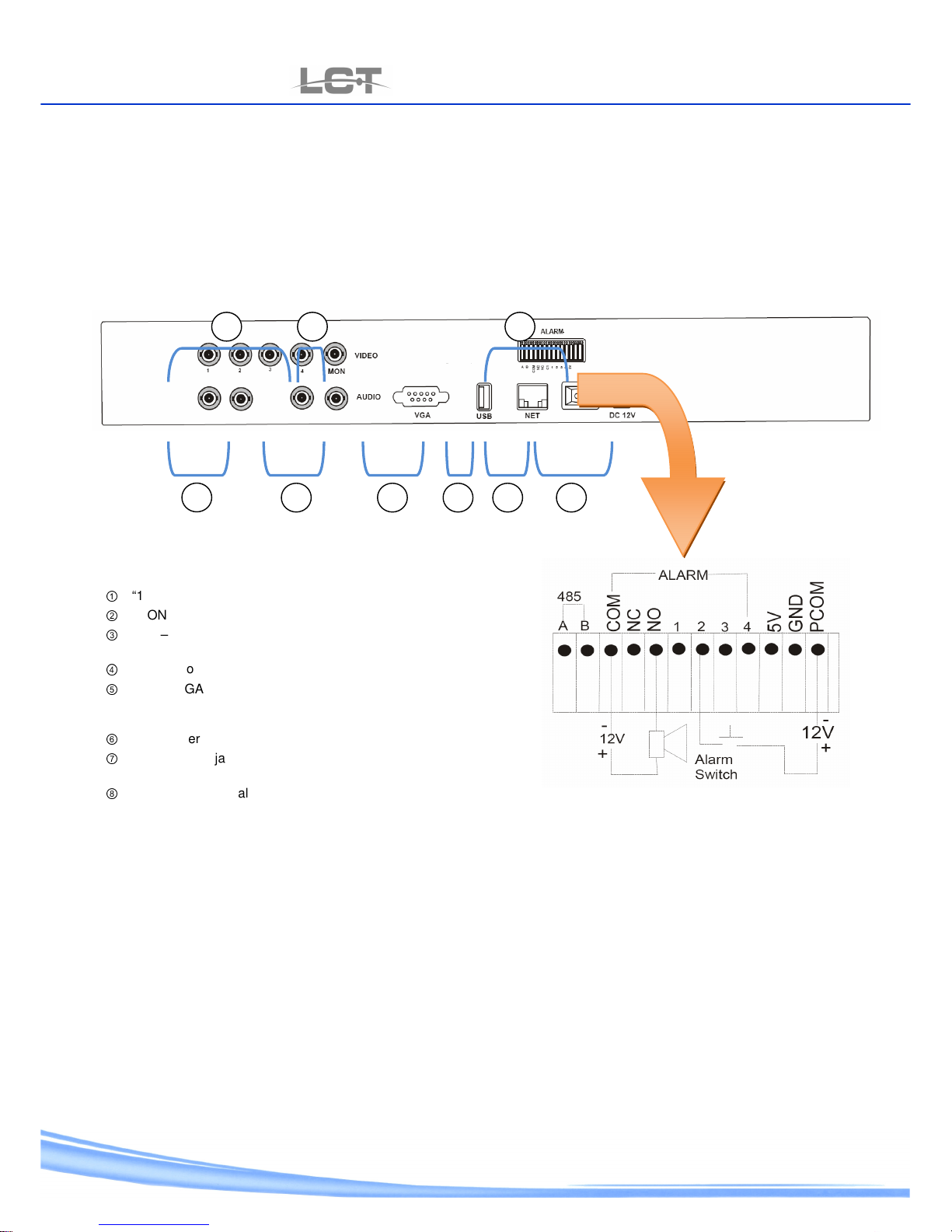
LCTVR6104
LCTVR6104LCTVR6104
LCTVR6104
①
“1-4”:BNC video input
②
“MON”:BNC Video output .
③
“LIN – RIN”:Left Audio input ,Right Audio input .
“LOUT – ROUT”:Left Audio output ,Right Audio
④
”: USB output .
⑤
“VGA”: VGA Video output (800x600 60Hz)
“USB Interface
for Backup
⑥
“NET”: interface RJ-45 port.
⑦
“DC12V” Minijack power connector and ON/OFF
power button
⑧
“ALARM” Terminal block for Alarm and RS-485
device.
For the top shape of the device outer side link the power cable as show carry back on top picture.
Page 7

USER MANUAL
LCTVR6104-8208-8216
www.hrcctv.com pag.7
485 A/B: link the 2 line wires some RS-485 wire line to along with make connection about the speed dome.
COM – NC – NO: power relay by alarm output. (common, normally close, normally open)
1 – 2 – 3 – 4: alarm input. No alarm channel is coupled and put in to action typical channel only..
For the top shape use the power source of12Vdc.
Page 8
USER MANUAL
LCTVR6104-8208-8216
pag.
8
www.hrcctv.com
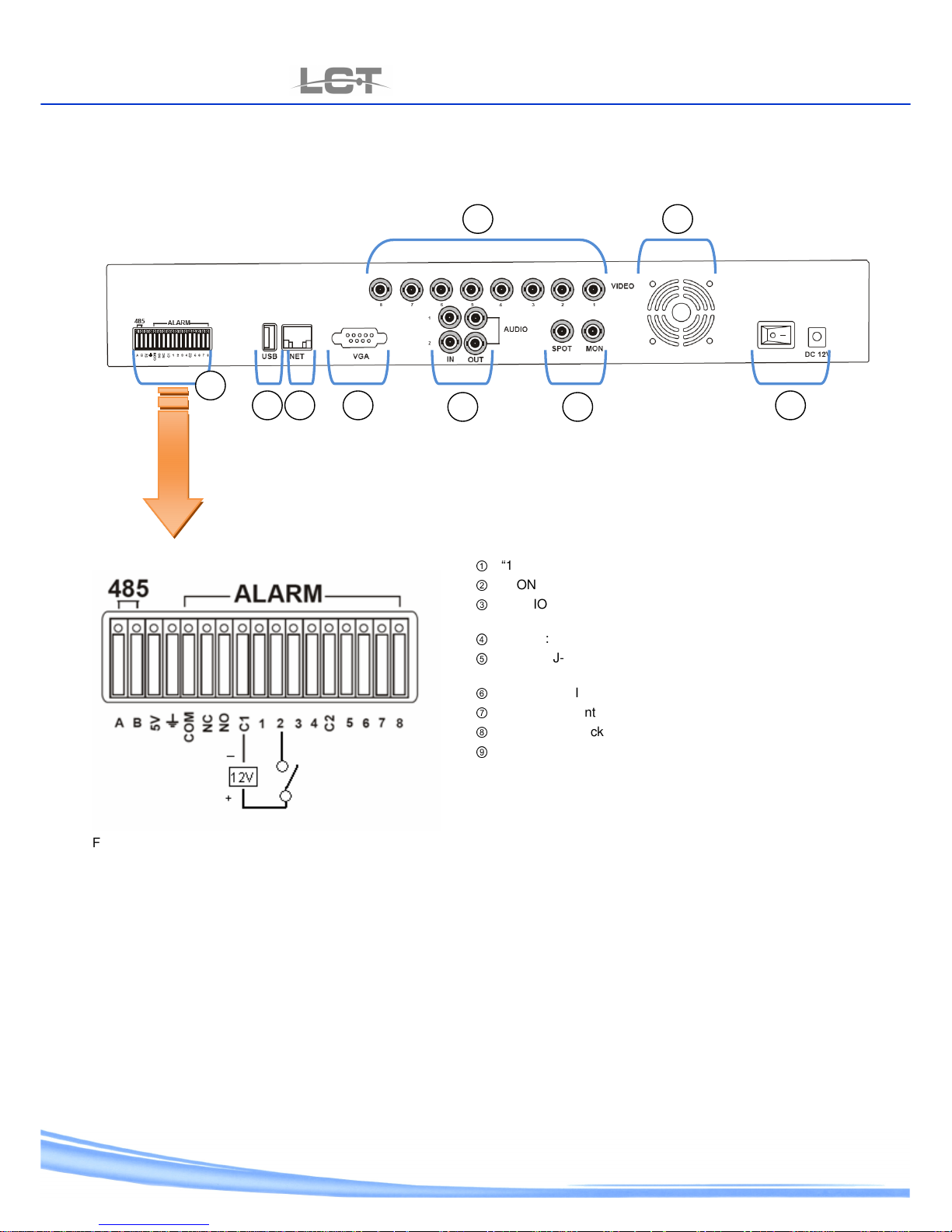
LCTVR8208
LCTVR8208LCTVR8208
LCTVR8208
f
①
“1-8”: BNC Video input .
②
“MON” e “SPOT”: BNC Video output .
③
“AUDIO IN/OUT” : Left & Right Audio input. Left & Right
Audio output.
④
“VGA” :VGA Video output (800x600 60Hz)
⑤
“NET”: RJ-45 Connector for net time link
⑥
“USB”: USB Interface of Backup.
⑦
“ALARM” potential devise outer side PTZ for alarm.
⑧
“DC12V” Minijack power and cook-off and power off.
⑨
Air-cooling
For the top shape of the device outer side link the power cable as show carry back on top picture.
485 A / B: link the 2 line wires some RS-485 wire line to along with make connection about the speed dome.
COM – NC – NO: power relay by alarm out put . (common, normally close, normally open)
1 – 2…8: alarm input . no alarm channel is coupled and put in to action typical channel only.
For the top shape use the power source of12Vdc.
1 9
2 3
4 5 6
7
8
Page 9
USER MANUAL
LCTVR6104-8208-8216
www.hrcctv.com pag.9
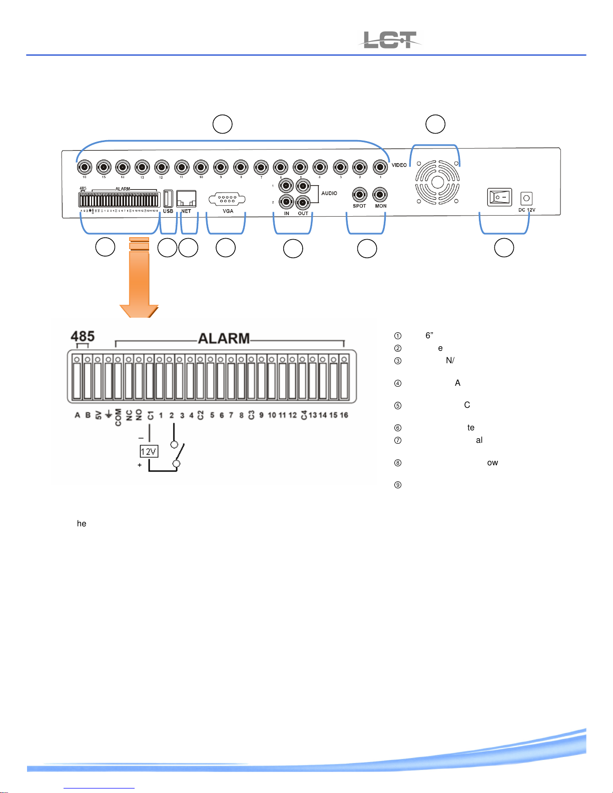
LCTVR8216
LCTVR8216LCTVR8216
LCTVR8216
①
“1-16” : BNC Video input .
②
“MON” e “SPOT”:BNC Video output.
③
“AUDIO IN/OUT”: Left & Right Audio
input. Left & Right Audio output.
④
“VGA”: VGA Video output (800x600
60Hz)
⑤
“NET”: RJ-45 Connector for net time
link
⑥
“USB”: USB Interface of Backup
⑦
“ALARM” potential device outer sider
PTZ for alarm
⑧
“DC12V” Minijack power and cookoff and power off
⑨
Air-cooling
For the top shape of the device outer side link the power cable as show carry back on top picture.
485 A/B: link the 2 line wires some RS-485 wire line to along with make connection about the speed dome.
COM – NC – NO: power relay by alarm out put . (common, normally close, normally open)
1 – 2…16: alarm input. No alarm channel is coupled and put in to action typical channel only.
For the top shape use the power source of 12Vdc.
1 9
2 3
4 5 6 7 8
Page 10
USER MANUAL
LCTVR6104-8208-8216
pag.
10
www.hrcctv.com
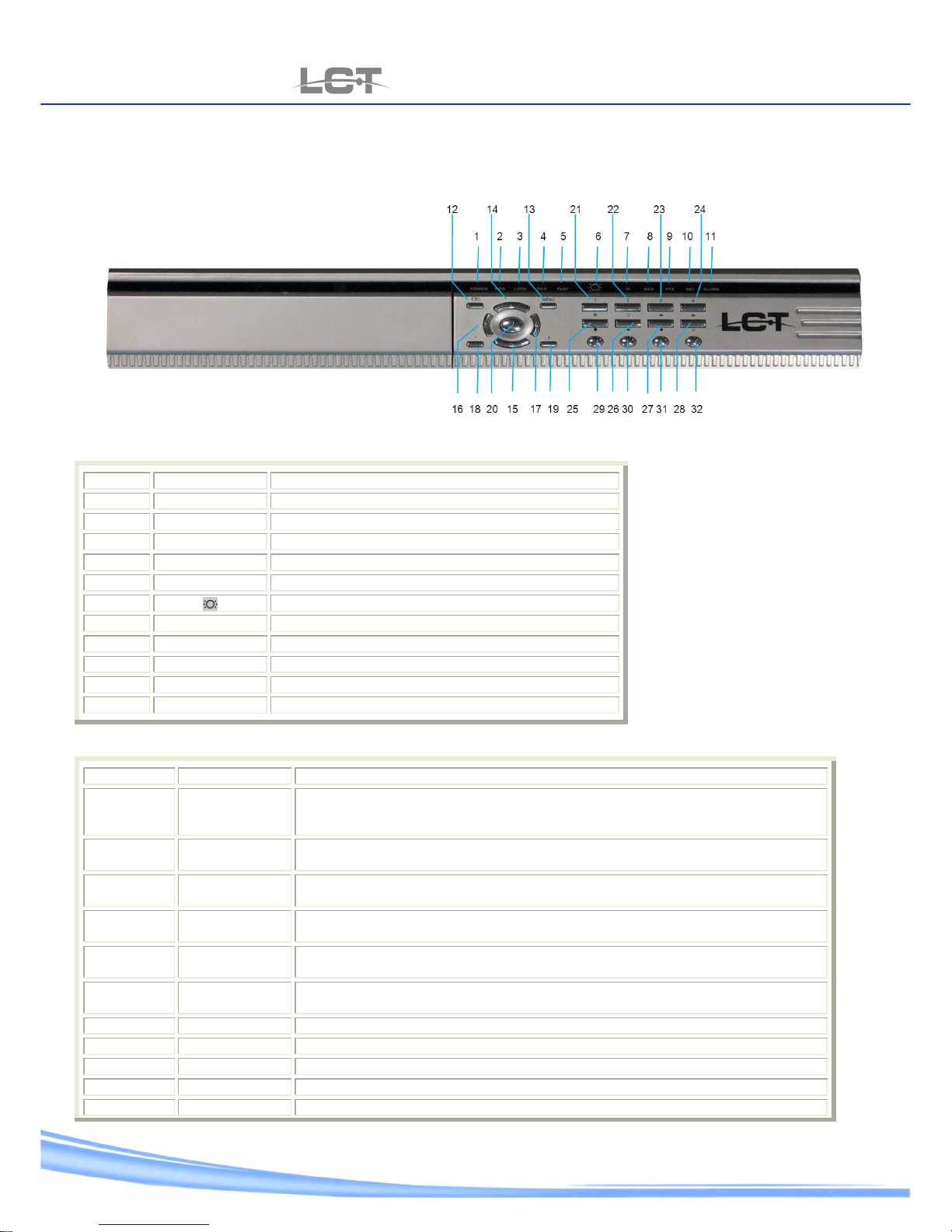
2.2 Head-on panel
LCTVR6104
LCTVR6104LCTVR6104
LCTVR6104
Indication LED
N° Symbol function
1 POWER Power – Standby
2 HDD Hard Disk reading / writing
3 LOCK Key locked
4 REC Recording on
5 PLAY Play
6
Status of remote control
7 IR Start receiving form remote control
8 SEQ Auto jump among stations
9 PTZ PTZ Control on
10 NET Network connection
11 ALARM Alarm output on
Keys function
N° Symbol Function
12 ESC press the ESC key will exit from lower level menu to upper level menu until fully exit
from the menu status including the info menu;in case of password status ,press the
ESC key after exit from the main menu will lock the machine.
13 MENU At running status, enter the menu setting status; at lock status (lock light up),press
this key to remind for password input.
14
Under the menu status , select items upwards ,under the PTZ control status , control
the ball machine to rotate upwards.
15
Under the menu status , select items downwards ; under the PTZ control status ,
control the ball machine to rotate downwards.
16
Under the menu status , select items leftwards ; under the PTZ control status ,
control the ball machine to rotate leftwards.
17
Under the menu status , select items rightwards ; under the PTZ control status ,
control the ball machine to rotate rightwards.
18 - Value down for the selected item.
19 + Value up for the selected item.
020
Confirmation key.
21 1 key1; 1 channel display
22 2 Key 2; channel 2 display
Page 11
USER MANUAL
LCTVR6104-8208-8216
www.hrcctv.com pag.11
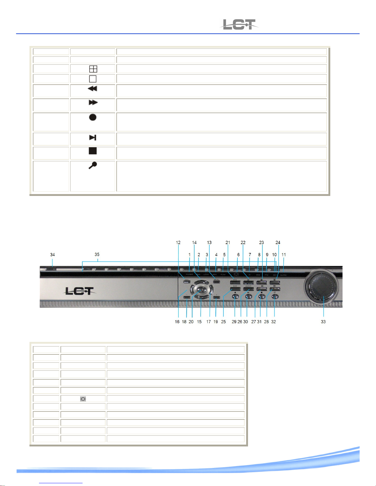
23 3 Key 3; channel 3 display
24 4 Key 4 ; channel 4 display
25
4-split display on monitor (1-4,5-8,9-12,and 13-16 in manner) .
26
Channel key single :the channel 1 display entire
27
At play status , press key to backward image at 2x speed ; further press key to
backward image at 4x speed ;finally press key to return normal play status .
28
At play status ,press key to forward image at 2x speed ; further press key to forward
image at 4x speed; finally press key to return normal play status .
29
At in-situ status , ;press key will enter video recording status (video recording
parameters are set under the system menu ) ;at video recording status , press the key
will stop video recording.
30
At in-situ status , press key to enter the play status and directly play the last file;
further press key to pause the play ,finally press key to continue to play.
31
At backup status , press key to stop backup; at video recording status , press key to
stop video recording ; at play status , press key to stop play.
32
At in-situ or play status ; press key to pup up the search menu with three available
search methods: time search / video file search / event search. Users can select the
wanted item and enter various search method sub-menu for search. At in-situ status ,
press key to enter the play status and directly play the last file; further press key to
pause the play ,finally press key to continue to play.
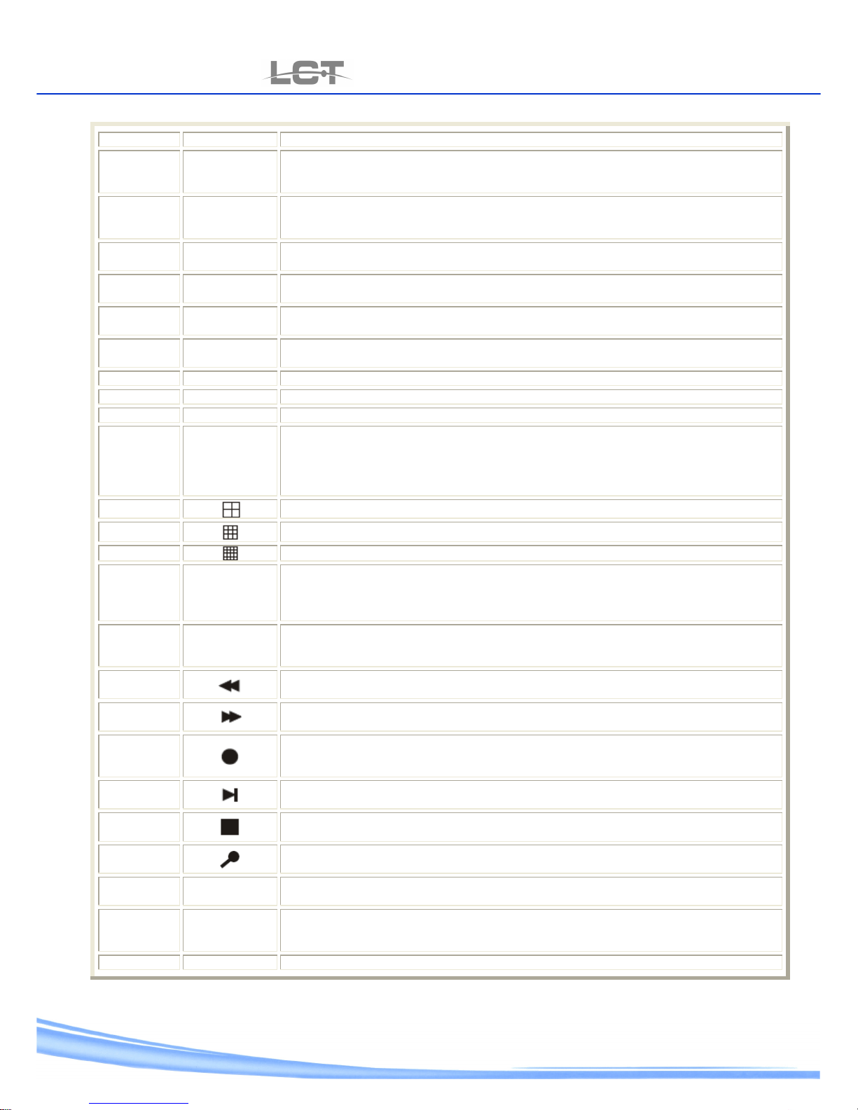
LCTVR8208
LCTVR8208 LCTVR8208
LCTVR8208 ---- LCTVR8216
LCTVR8216 LCTVR8216
LCTVR8216
Indicating LED
N° Symbol Function
1 POWER Power – Standby
2 HDD Hard Disk reading / writing
3 LOCK
Key locked
4 REC Recording on
5 PLAY play
6
Status of remote control
7 IR Start receiving form remote control
8 SEQ Auto jump among stations
9 PTZ PTZ Control on
10 NET Network connection on
11 ALARM Alarm output on
Page 12
USER MANUAL
LCTVR6104-8208-8216
pag.
12
www.hrcctv.com
Function keys
N° Symbol Function
12 ESC
press the ESC key will exit from lower level menu to upper level menu until fully exit from
the menu status including the info menu;in case of password status ,press the ESC key
after exit from the main menu will lock the machine
13 MENU
press the ESC key will exit from lower level menu to upper level menu until fully exit from
the menu status including the info menu;in case of password status ,press the ESC key
after exit from the main menu will lock the machine
14
Under the menu status , select items upwards ,under the PTZ control status , control the
ball machine to rotate upwards.
15
Under the menu status , select items downwards ; under the PTZ control status , control
the ball machine to rotate downwards.
16
Under the menu status , select items leftwards ; under the PTZ control status , control the
ball machine to rotate leftwards.
17
Under the menu status , select items leftwards ; under the PTZ control status , control the
ball machine to rotate leftwards.
18 - Value down for the selected item
19 + Value up for the selected item.
20
Confirmation key
21 PTZ
At on-situ preview status , press the PTZ key will display the PTZ word on top of monitor
screen , meaning that the equipment is under PTZ control and press channel key will
change control channels. PTZ control parameters of each channel may be revised under
the system menu . re-press the PTZ key or press the ESC key will exit the PTZ control
status.
22
4-split display on monitor (1-4,5-8,9-12,and 13-16 in manner) .
23
9-split display on monitor (1-8 and 9-16 in manner )
24
16-split display on monitor (this key won’t work at 8-line DVR ).
25
BACK
At search status , after selecting the searched data, press the BAK key will backup such
data to a U drive ( description to search operation is given in the later part ); at play
status ,the BAK key is used to backup the currently played image and voice ; at backup
status , press the key will stop backup.
26 AUDIO
Press this key to display on left top screen, meaning audio output is on , subsequently
press this AUDIO key to cancel such display , meaning audio output is off . At in-situ status
, in-situ voice is outputted ;at play status ,recorded voice is outputted.
27
At play status , press key to backward image at 2x speed ; further press key to backward
image at 4x speed ;finally press key to return normal play status .
28
At play status , press key to forward image at 2x speed ; further press key to forward
image at 4x speed ;finally press key to return normal play status.
29
At in-situ status , ;press key will enter video recording status (video recording
parameters are set under the system menu ) ;at video recording status , press the key will
stop video recording.
30
. At in-situ status , press key to enter the play status and directly play the last file; further
press key to pause the play ,finally press key to continue to play.
31
At in-situ status , press key to enter the play status and directly play the last file; further
press key to pause the play ,finally press key to continue to play.
32
At in-situ status , press key to enter the play status and directly play the last file; further
press key to pause the play ,finally press key to continue to play.
33 Jog-Shuttel
Sideout ring (Shuttel) equivalent of key value up, down and right, left
Inside ring (jog) equivalent of key up and down
34 INFO
At running status , press INFO key will pup up system information including details of hard
disk use ;press the ESC key will exit the INFO menu ; at standby status (power indicating
light in green), press the INFO key for 3 seconds will turn on the equipment.
35 1,2,3…..16 Key channel: display the relative channel.
Page 13
USER MANUAL
LCTVR6104-8208-8216
www.hrcctv.com pag.13
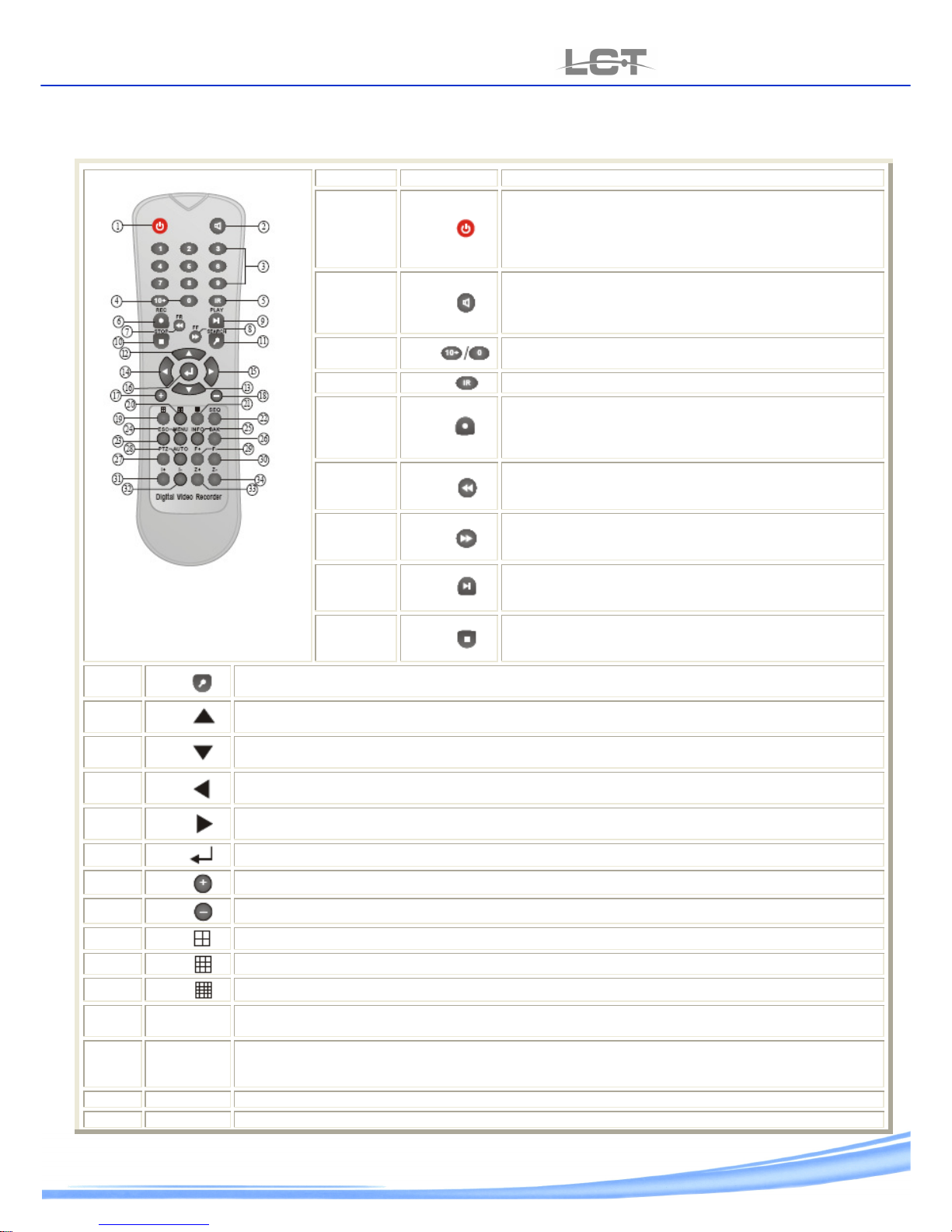
2.3 Remote control
S.N.
key briefing
1.
At normal running status , press this power key to pop up the
reminder menu, asking whether to shut down , after
confirmation ,the machine will automatically shut down in
safe mode and enter the standby status , with the power
indicating light on panel from red to green.
2.
Press this key to display on left top screen , meaning audio
output is on, subsequently press this key to cancel such
display , meaning audio output is off. At in-situ status , in-situ
voice is output ;at play status,recorded voice is outputted.
3.
select channels bigger than 9 by combining the 1-9 keys and
0 key
4.
Select remote control ID
5.
At in-situ status , ;press key will enter video recording status
(video recording parameters are set under the system menu )
;at video recording status , press the key will stop video
recording.
6.
At play status , press key to backward image at 2x speed ;
further press key to backward image at 4x speed ;finally
press key to return normal play status .
7.
At play status , press key to backward image at 2x speed ;
further press key to backward image at 4x speed ;finally
press key to return normal play status .
8.
At play status , press key to backward image at 2x speed ;
further press key to backward image at 4x speed ;finally press
key to return normal play status .
9.
At play status , press key to backward image at 2x speed ;
further press key to backward image at 4x speed ;finally press
key to return normal play status .
10.
At play status , press key to backward image at 2x speed ; further press key to backward image at 4x speed
;finally press key to return normal play status .
11.
At play status , press key to backward image at 2x speed ; further press key to backward image at 4x
speed ;finally press key to return normal play status .
12.
At play status , press key to backward image at 2x speed ; further press key to backward image at 4x
speed ;finally press key to return normal play status .
13.
At play status , press key to backward image at 2x speed ; further press key to backward image at 4x
speed ;finally press key to return normal play status .
14.
At play status , press key to backward image at 2x speed ; further press key to backward image at 4x
speed ;finally press key to return normal play status .
15.
Confirmation key
16.
Value down for the selected item or revise it
17.
Value up for the selected item or revice it
18.
4-split display on monitor ( 1-4,5-8,9-12 and 13-16 in manner )
19.
9-split display on monitor (1-8 and 9-16 in manner )
20.
16-split display on monitor ( this key won’t work at 8-line DVR )
21.
SEQ
At in-situ preview status, press the SEQ key toh ave the monitor automatically switching big screen image
of channel 1-16 and re-press the key to stop jumping stations.
22.
ESC
press the ESC key will exit from lower level menu to upper level menu until fully exit from the menu status
including the info menu ;in case of password status ,press the ESC key after exit from the main menu will
lock the machine
23.
MENU At in-situ status ,press this MENU key to enter the menu setting status.
24.
INFO At in-situ status , press the info key will pup up hard disk information , press the ESC key will exit the INFO
Page 14
USER MANUAL
LCTVR6104-8208-8216
pag.
14
www.hrcctv.com
menu , in case no installed disk, press this INFO key makes no sense.
25.
BAK Backup key
26.
PTZ
At on-situ preview status , press the PTZ key will display the PTZ word on top of monitor screen , meaning
that the equipment is under PTZ control and press channel key will change control channels. PTZ control
parameters of each channel may be revised under the system menu . re-press the PTZ key or press the
ESC key will exit the PTZ control status.
27.
AUTO At PTZ control status , this AUTO key used to let PTZ automatically rotate.
28.
F+ At PTZ control status , this F+ key used to extend focal length
29.
F- At PTZ control status ,this F- key used to shorten focal length
30.
I+ At PTZ control status , this I+ key used to enlarge iris
31.
I- At PTZ control status , this I- key used to reduce iris
32.
Z+ At PTZ control status, this Z+ key used to Zoom + on
33.
Z- At PTZ control status , this Z – key used to Zoom out
Page 15
USER MANUAL
LCTVR6104-8208-8216
www.hrcctv.com pag.15
2.4 HD Installation
2.4.1 Hard Disk select
At the right working of the device ,used HD Seagate IDE 7200 RPM for LCTVR6104 and Seagate SATA 7200RMP for LCTVR8208
LCTVR8216. to get out side security and reliability used HD Seagate set SV35; code HRX160SV – HRX250SV – HRX500SV IDE
version HRX160SVS – HRX250SVS SATA version .
2.4.2 Hard Disk estimate size
Power of hard disk well-supported by DVR is between 120GB and 500GB.
Occupation Hard disk (Resolution CIF - 25 fps – middle quality):
LCTVR6104: ~800MB/H
LCTVR8208 e LCTVR8216: ~1,3GB/H
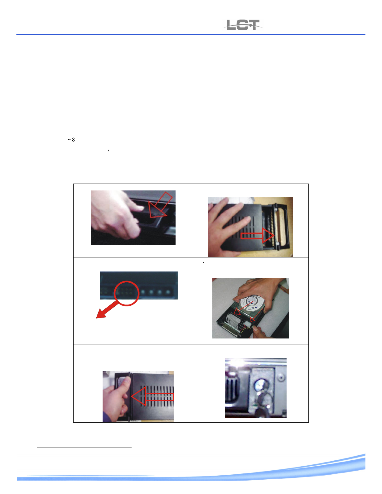
2.4.3 Hard Disk mounting
The actions by right installation of hard-disk.
1. take out the cassette of DVR
2. open the cassette and take off the
cover.
3. setup the Jumper of Hard Disk as
Master.
Jump to Master
4.
link the flat and the power. Lock on
the equip with HD
.
5. close again the cover and put on the
cassette in to DVR, play attention, well link.
.
6. at hope chest close with key.
.
If you want to use other HD, open the DVR and lock on . setup as slave and link the power.
**the picture and procedura indicated there fore assemglinb of one HD IDE.
For the version sata consult the boo
Page 16
USER MANUAL
LCTVR6104-8208-8216
pag.
16
www.hrcctv.com
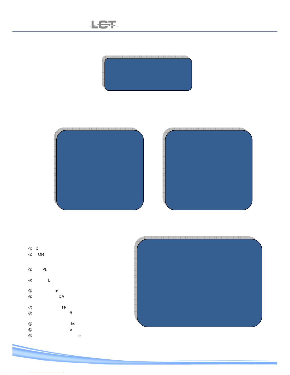
3 MENU SETUP
Control to have got and make all link befor to start. Give the power and light up the DVR. Wait little while ,the new HD put in
after the start and the following window safe bet show at video.
Select ENTER and wait the fulfillment of the format the DVR. After some moment the buzzer will give a warning in order to
advise that is possibile to use the DVR. In to course of action live press MENU to go in the principal menu. Use the keys down;
up; exit; enter; right; left;+ and – to move along in the menu.
3.1 Main menu
LCTVR6104 LCTVR8208 – LCTVR8216
Select SETUP System and press ENTER.
3.2 Setup system
①
DATE / TIME: to adjust date/time.
②
FORMAT: to set the format of display with ASIA
(AAAA/MM/GG), Europe (GG/MM/AAAA) e USA
(MM/GG/AAAA)
③
DISPLAY DATE/TIME: to set the display of
date/time(high, low, OFF)
④
SPLIT LINE: to select the split line color (white –
black – grey – off)
⑤
BUZZER On/Off: used to turn on/off the buzzer
⑥
VIDEO STANDARD: to select PAL o NTSC a borard
the link of monitor.
⑦
ID REMOTO: used to turn on/off the remote control.
⑧
PASSWORD On/Off: used to turn on/off the
password by menu.
⑨
PASSWORD :used the password trust (to unlock )
⑩
DEFAULT: to restore the DVR default.
⑪
LANGUAGE: used to select the language (ITALIAN – ENGLISH)
MAIN MENU
1.SYSTEM SETUP
2.CAMERA SETUP
3. RECORD SETUP
4 .SCHEDULE SETUP
5 MOTION SETUP
6. PTZ SETUP
7. NETWORK SETTING
8.SPOT SETUP
9.CD/RW BACKUP
10.DISK MANAGEMENT
11.LOG LIST
MAIN MENU
1.SYSTEM SET
2.CAMERA SET
3.RECORD SET
4.SCHEDULE SET
5 MOTION SET
6. PTZ SET
7. NETWORK SET
8.DISK MANAGE
9.LOG LIST
SETUP SYSTEM
2008/07/22 12:08:42
TIME FORMAT:
EURO (DD/MM/YYYY)
TIME DISP POS: TOP
BORDER DISP: WITHE
BUZZER SWITCH: OFF
VIDEO FORMAT: PAL
REMOTO ID: ON
SYSTEM PASSWORD : OFF
PASSWORD: 111111
SOFTWARE UPDATE: ENTER
DEFAULT LOAD: ENTER
LANGUAGE: ENGLISH
FORMAT HDD?
ENTER Cancel
Page 17

USER MANUAL
LCTVR6104-8208-8216
www.hrcctv.com pag.17
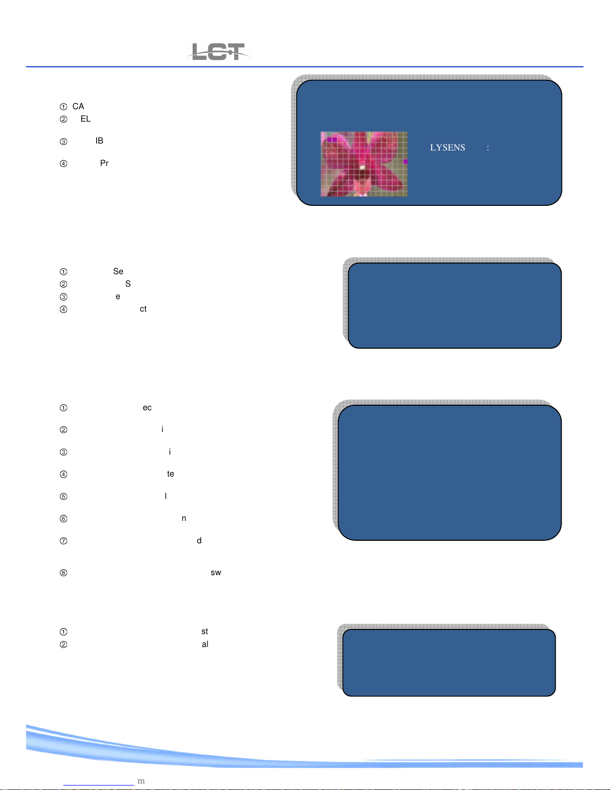
3.3 Camera setup
①
CAM: used to select the channel to set up
②
CAMERA NAME: put the name of camera wanted
③
BRIGHTNESS’: used to adjust brightness of
picture.
④
HUE(color): used to adjust color of picture
⑤
CONTRAST: used to adjust contrast
⑥
SATURATION (livel): used to adjust intensity color.
⑦
HORIZONTAL: used to adjust the horizontal
position of picture.
⑧
VERTICAL: used to adjust the vertical position of
picture.
3.4 Record SET
①
RESOLUTION: Select the resolution to like for recording: CIF 352x288 o D1 704x576
②
OVERWRITE: on/off the overwrite of picture present on the Hard Disk.
③
AUDIO ON/OFF: on/off the recording of audio .
④
QUALITY: press ENTER to access of setup.
I. CAM:( all channel are single manageable ) used to select the channel to be set.
II. QUALITY: set the level crossing wanted between high – low – normal.
III. FRAME RATE: used to select the frame rate wanted of each channel.
**NB: set the mode of resolution CIF (352x288), the frame rate it will be to the highest degree 25fps for channel (Real Time) at
type LCTVR6104 e LCTVR8208.
Set the mode of resolution D1 (704x576), the frame rate it will be to the highest degree 6fps for channel.
3.5 Schedule SET
①
CAM: Select the channel to set up.
②
MODALITY: AUTO to turned on the time band or
MANUALE to turned on the recording.
③
GG: Select the date to set up.
④
SEG 1-4: set up the time wanted.
⑤
MODALITY:
a. TIME, turned on the recording set.
b. MOTION :put into action only case of motion.
c. ALARM :put into action only in case contact
alarm.
d. ALARM+MOTION put into action recording in
case contact alarm or motion.
CAMERA SETUP
CAM: CAMERA 01
CAM
ERA NAME: CAM 01
BRIGHTNESS’: 00
HUE : 00
CONTRAST : 00
SATURATION : 00
IMAGE HDELAY: 00
: IMAGE VDELAY : 00
SETUP RECORDING
RESOLUTION : 720 x 576
OVERWRITE : ON
AUDIO ON/OFF : OFF
OTHER : ENTER
RECORDING QUALITY SETUP
CAM : 1 2 3 4
QUALITY : HIGH HIGH HIGH HIGH
FRAME RATE : 25 25 25 25
SCHEDULE SETUP
CAM : CAMERA 01 REC MODE: AUTO
TIME : SUN
START TIME END TIME ALARM TYPE
SEG 1: 00:00 - 03:00 TIME
SEG 2: 03:00 - 04:00 ALARM+MOTION
SEG 3: 00:00 - 00:00 TIME
SEG 4: 00:00 - 00:00 TIME
Page 18
USER MANUAL
LCTVR6104-8208-8216
pag.
18
www.hrcctv.com
3.6 Motion SET
①
CAM: Select the channel to start.
②
VELOCITY: Select the level crossing of quickness to
put into action between HIGH – LOW – NORMAL.
③
SENSIBILITY: Select the level crossing of sensibility
between HIGH – LOW – NORMAL.
④
AREA: Press ENTER for entry into aree.
3.7 PTZ SET
①
CAMERA: Select the channel to setup.
②
BAUDRATE: Select the baudrate corresponding to the Speed Dome
③
ID: setup the ID address corresponding to the Speed Dome.
④
PROTOCOL: select the protocol to like between PELCO_P and
PELCO_D
For the control on/off of PTZ press PTZ about the remote control or
the key present in the frontal panel ( 8 and 16 channel), for other
detail ,refered to chart (pag 9-12)
3.8 Network SET
①
IP ADDRESS: Select the IP in agreement to the net .
Default 192.168.001.1 33
②
GATEWAY: setup GW in agreement to the net.
Default: 192.168.001. 001
③
SUBNETMASK: start SM in agreement to the net .
Default 255.255.255.000
④
DVR PORT :setup the gate language need to software . Default
6802
⑤
IE PORT: start the gate language need for to link up through
Browser IE. Default 0080
⑥
USER’S NAME: start to user name need to remote access .
Default USER01
⑦
PASSWORD: setup the password need for remote log-on( access)
to user level .
Default 111111
⑧
SUPER PASSWORD: setup the password need for remote log-on (access) to administrator level.
Default 000000
3.9 Spot (only 8 and 16 channel)
①
MODALITY: Select the channel to start.
②
INTERVAL: Select to set the interval time for recycled. (1s-10s)
(time of swiitchers)
MOTION SET
CAM: CAMERA 01
SPSENS :
LOW
LYSENS : LOW
AREA EDIT : ENTER
PTZ SET
CAM : CAMERA 01
BAUDRATE : 2400
ID : 01
PROTOCOL : PELCO_D
NETWORK NET
IP ADDRESS : 010.000.002.141
GATEWAY : 010.000.002.001
SUBNETMASK : 255.255.255.000
DVR PORT : 6802
IE PORT : 0080
USER’S NAME : USER01
PASSWORD : 111111
SUPER PASSWORD : 000000
SPOT SETUP
CAMERA : CAMERA 01
OUTPUT INTERVAL : 00Sec
Page 19
USER MANUAL
LCTVR6104-8208-8216
www.hrcctv.com pag.19
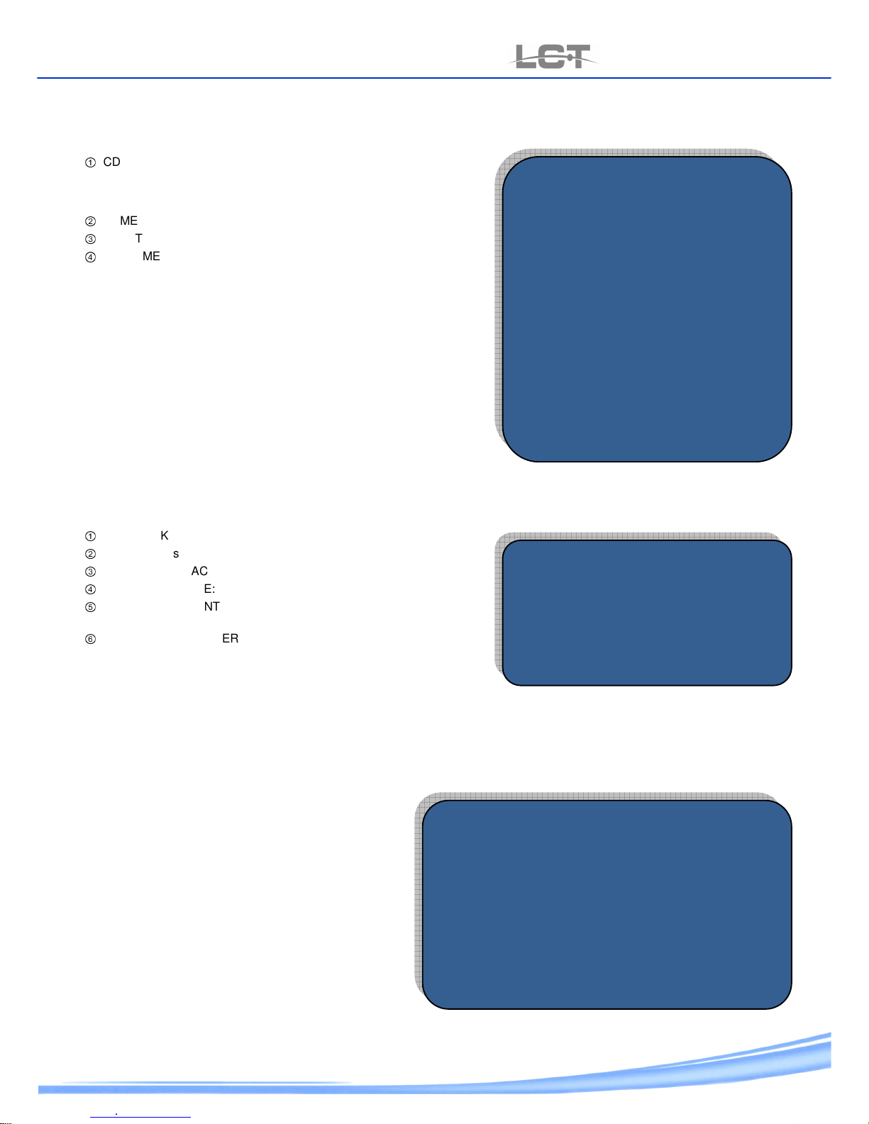
3.10 DVD-CD/RW Backup( 8 AND 16 CHANNEL)
①
CD TYPE: Select the format wanted between the following option:
I. CD 12cm
II. CD 8cm (mini cd)
III. DVD
②
CAMERA: Select the channel which to wanted copy the picture .
③
START TIME: Select start date and time of the recording wanted copy.
④
END TIME: Select start date and time of the recording wanted copy .
to make the search for backup until max 3 camera is possible .
3.11 DISK manage
①
HARD DISK N°: Select HD to piloting
②
CAPACITY: select to display capacity of HD .
③
BANK(FREE SPACE): left percentage of bank.
④
ERROR DIM. ZONE: info to any sector faulty on the disk to use.
⑤
CANCEL: Press ENTER to delete all recording present on the
Hard Disk.
⑥
FORMAT: Press ENTER for totaly format of Hard Disk and find the
right working. (clear all date).
3.12 LOG search
The menu is used to search video recording information
when the device is put on , put off, that be manual or
lack in net .
CD/RW BACKUP
CD TYPE : 12cm(LESS
THAN550M)
CAMERA : 01 ---B
START TIME : 2009/07/22 22:00
END TIME : 2009/07/22 22:00
CAMERA : 01 ---B
START TIME : 2009/07/22 22:00
END TIME : 2009/07/22 22:00
CAMERA : 01 ---B
START TIME : 2009/07/22 22:00
END TIME : 2009/07/22 22:00
TOTAL:……….B
TOTAL:
-----
MB BACKUP
LOG SEARCH
START TIME : 22/07/2008
END TIME : 22/07/2008 SEARCH
01/01
N°. EVENT TIME
01 POWER ON 22/07/2008 14:47:55
02 ----------------- ------------- ---------03 ----------------- ------------- ---------04 ----------------- ---------------- --------05 ___________ __/__/____ __:__:__
DISK MANAGE
DISK NAME : HDD 1
DISK SIZE : 149 GB
REMAIN SIZE : 046%
BAD SIZE : 000G
RECORD CLEAR : ENTER
DISK FORMAT : ENTER
Page 20
USER MANUAL
LCTVR6104-8208-8216
pag.
20
www.hrcctv.com
4 BASE PLANNING
4.1 Manual recording
It is not plan planning time to start up of Default by DVR ..
For start Manuel recording press REC .
LED light up to indicat real recording and the symbol . seen on the any channel.
To bang up recording press STOP. .
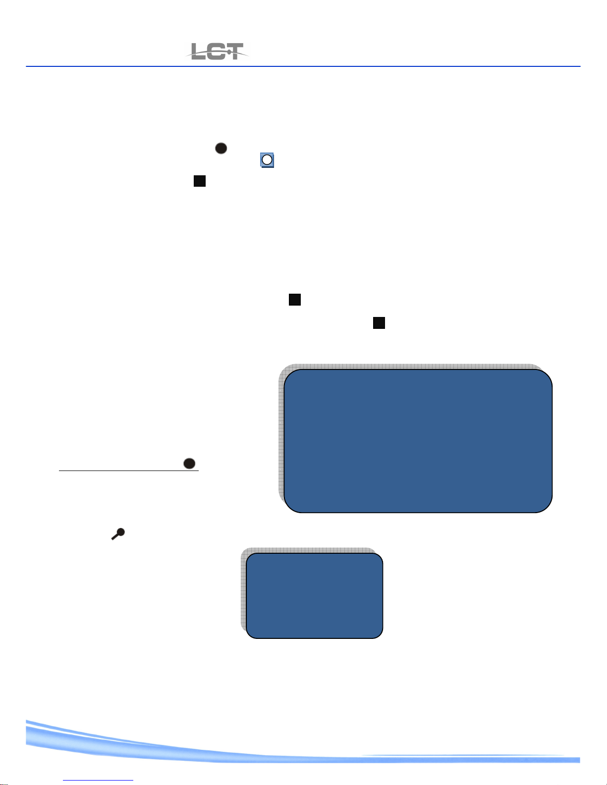
4.2 planned recording
It is not plan planning time to start up of Default by DVR .
It is possible to be lead each channel sole a 4 strips time for any day of week .and set up modality to recording :
-TIME: this modality of recording make capable to be continuous at lapse of time included in the time band . the symbol “T”
seem on the video.
-ALARM: used this modality , the channel start not turn out to recorded . if the DVR are not obtain exterior impulse put in of
alarm . the symbol “S” seem on the video and the symbol during the stillness.
-MOTION: used this modality , the channel start not turn out to recorded, if the DVR are not identify the picture movement of
air set in the past at setup motion .the symbol “M” seem on the video and symbol during the stillness.
-ALARM + MOTION: used this modality , the channel start not out to recorded ,if the DVR are not obtain exterior impulse or
identify movement of air in the past at setup motion
Accede to setup time menu make really
personalization.
-select AUTO on the modality voice to make capable
the recording planning .
-Select the manageable channel then day of the week
need.
- setup the strips time and the recording modality .
-exit of the menu and press REC .
4.3 Search
The DVR give aid to 3 ways of search : time search, RECORD search, EVENT search.
Press search to open the next sereen :
Select “TIME SEARCH” if know the date and time of the copy recording .
Select “ RECORD SEARCH” to search the file wanted.
Select “ EVENT SEARCH “ to display the recording.
SCHEDULE SETUP
CAM : CAMERA 01
REC MODE AUTO
TIME : SUN
START TIME END TIME ALARM TYPE
SEG 1: 00:00 - 24:00 TIME
SEG 2: 00:00 - 24:00 ALARM+MOTION
SEG 3: 00:00 - 24:00 TIME
SEG 4: 00:00 - 24:00 TIME
SEARCH MENU
TIME SEARCH
RECORD SEARCH
EVENT SEARCH
Page 21

USER MANUAL
LCTVR6104-8208-8216
www.hrcctv.com pag.21
4.3.1 search time and BACKUP USB
After to have selected search time ,the next serene appear .
at these video ,come to show the recording present in the hard disk.
“RECORD START TIME” and “END RECORD TIME” show the
first or very old or most recent recording on the HD.
Setup the recording start time and date to copy of start
time voice and press up “PLAY” to start play back .
In modality channel ,the play back come to start ;press
channel key to select the camera need ,press” STOP” to
arrest the play back or USB entry, pre BAK to make up the
picture that is play back (for LCTVR6104 BAK is present on
the remote control).
To make in the teeth of the picture backup without
display ,select one file to take away. Press “ BACKUP” and
wait the end of process.
4.3.2 Record search and BACKUP USB
After to have selected record search ,the next serene appear .
At video come to show the recording present in the
hard disk.
“ RECORD START TIME” and “ RECORD END TIME” show
the first or very old or most recent recording on the
hard disk.
Setup the recording day need to look for copy of
“DATE/TIME” voice and select search , the DVR show
the list of the file recording ask, select one file and
press up “PLAY” to start play back.
In modality channel ,the play back come to start ,
press channel key to select the camera need , press”
STOP” to arrest the play back or USB entry, press BAK
to make up the picture that is play back (for
LCTVR6104 BAK is present on the remote control).
To make in the teeth of the picture backup without
display , select one file to take away. press “ BACKUP”
and wait the end of process.
4.3.3 event record search and BACKUP USB
After to have selected event search , the next serene appear.
At the video , come to show the recording present in
the hard disk.
“RECORD START TIME” and “ RECORD END TIME,” show
the first or very old or most recent recording on the
hard disk.
Select the channel need to search event, then is
necessary to fix which event search ,so select between
MOTION and ALARM, the date and select search . the
DVR show the list of the file recording ask , select one
file and press up “PLAY” to start play back.
In modality channel , the play back come to start
,press key to select the camera need, pres” STOP” to
arrest the play back or USB entry, press BAK to make
up the picture that is play back (for LCTVR6104 BAK is
present on the remote control).
RECORD SEARCH
RECORD FISRT TIME: 07/05/2008 19:05:38
RECORD LAST TIME: 08/05/2008 08:45:26
TIME 07/05/2008 SEARCH
N° TIME SIZE
01 ------------- ----- 02 ------------- ----- 03 ------------- ------ 04 -------------- ------Prev.
TIME SEARCH
RECORD FIRST TIME: 25/06/2008 23:04:02
RECORD LAST TIME: 17/07/2008 10:21:12
START TIME: 07/05/2008 12:20
(BACKUP) END TIME: 08/05/2008 08:45
BACKUP PLAY
EVENT RECORD SEARCH
RECORD FIRST TIME: 07/05/2008 19:05:38
RECORD LAST TIME: 08/05/2008 08:45:26
CAMERA:
CAMERA 01 EVENT: ALARM
DATE 07/05/2008 SEARCH
N° TIME
01 -----------
02 -----------
03 -----------
Precv
Page 22
USER MANUAL
LCTVR6104-8208-8216
pag.
22
www.hrcctv.com
5 NETWORK CONNECTION
51 IP address configuration
Bifore to go ahead check up the next point:
• Control the connection to the net of DVR and PC
• Check up on the DVR and PC belong to same of IP address.
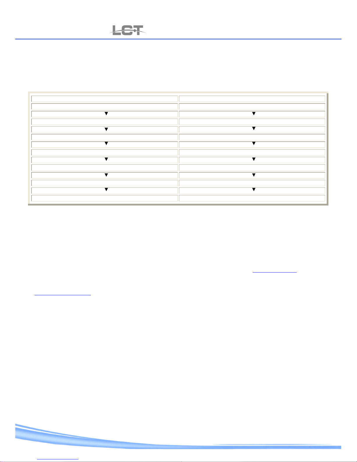
MS Windows 2000 / XP MS Windows VISTA
Start Start
Control panel Control panel
Net Connexion Net Connexion center
Key right of Mouse up Connection to the net status LAN Status display
Property Property
Select Protocol Internet TCP/IP Select Protocol Internet TCP/IP v.4
Property Property
The IP address information at meet with general schedule .
The IP shape is to get setup automatically IP address ,is necessary to prompt used of MS-DOS to set IP address. Contact the
administrator of net.
• After control PING ***.***.***.*** (* IP address of DVR) ,Prompt the connection control.
5.2 connection by Internet Explorer
- open Internet Explorer
- press IP address to machine of the address task bar:
At DVR for instance is setup address 192.168.1.133, press of the IE address task bar and screw http://192.168.1.133
The IE PORT setup of the menu and setup to net (cap.3.8), that be different of the 80 PORT (default), is necessary to specify the
port .
At DVR for instance is setup address 192.168.1.133 and IE PORT 1025, press of the IE address task bar and screw
http://192.168.1.133:1025
The system put on state of alert pop-up that the installation need of ActiveX HtmlAnvViewcab. Agree to carry on the installation.
If the installation is not go well , pursue the instruction:
-press task bar of the menu of Internet Explorer up tool then up option .
Each other to open the next window:
Open IE and input DVR address in the address column. For example, if your DVR IP is 10.1.27.200, then please input
http:// 10.1.27.200 in IE address column.
System pops up warning information to ask you whether install webrec.cab control or not. Please click yes button.
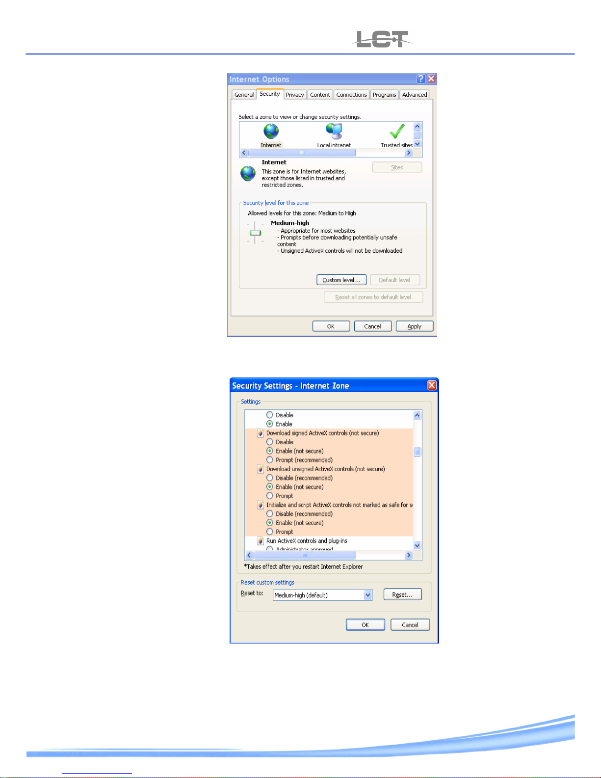
If you can’t download the ActiveX file, please modify your settings as follows. See
Page 23
USER MANUAL
LCTVR6104-8208-8216
www.hrcctv.com pag.23
Press up “security” and after made up “personal level”:
each other to open the next window
Save and come back at input IP address for reboot of the Control installation ActiveX.
Page 24
USER MANUAL
LCTVR6104-8208-8216
pag.
24
www.hrcctv.com
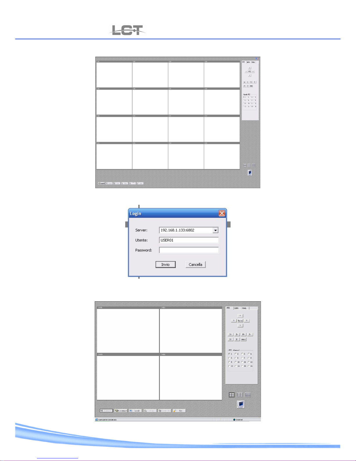
End installation , the next screen show:
Click up plug in to make at device
the next screen show :
At DVR put in IP address assigned after the DVR PORT(cap.3.8), the user name and the Password that are be setup of menu
and net setup (cap.3.8).
Default password to user level : 111111
Default password to Administrator level : 000000
Page 25
USER MANUAL
LCTVR6104-8208-8216
www.hrcctv.com pag.25
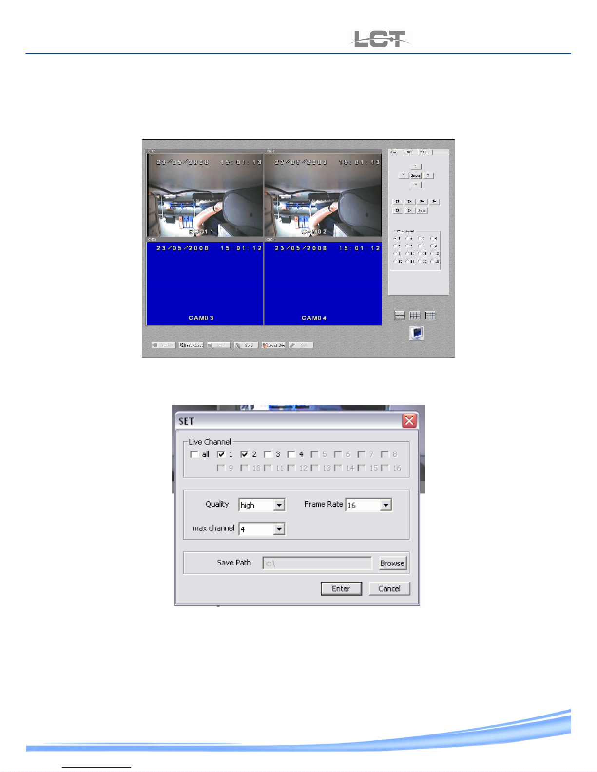
Press put in and the screen show:
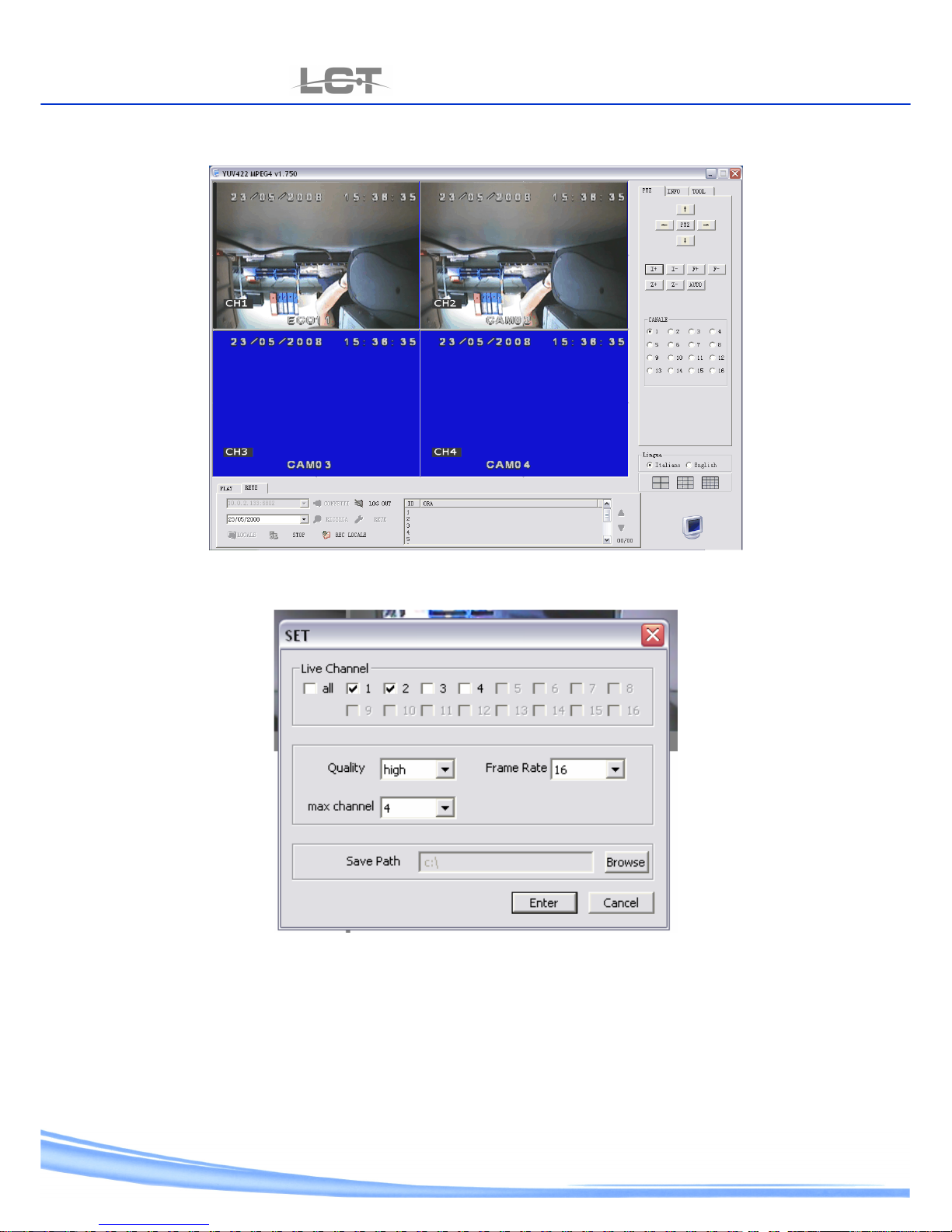
Is possible to make the next operations by means of plain interface :
-Press Local to display the Live picture.
-Press Stop to stop the display or local Rec for recording the picture in the teeth of computer.
N.B. for LCTVR6104 ,the local recording is start sole .
-for setup the recording parameters is necessary to stop the live display .so press set to access of the next screen.
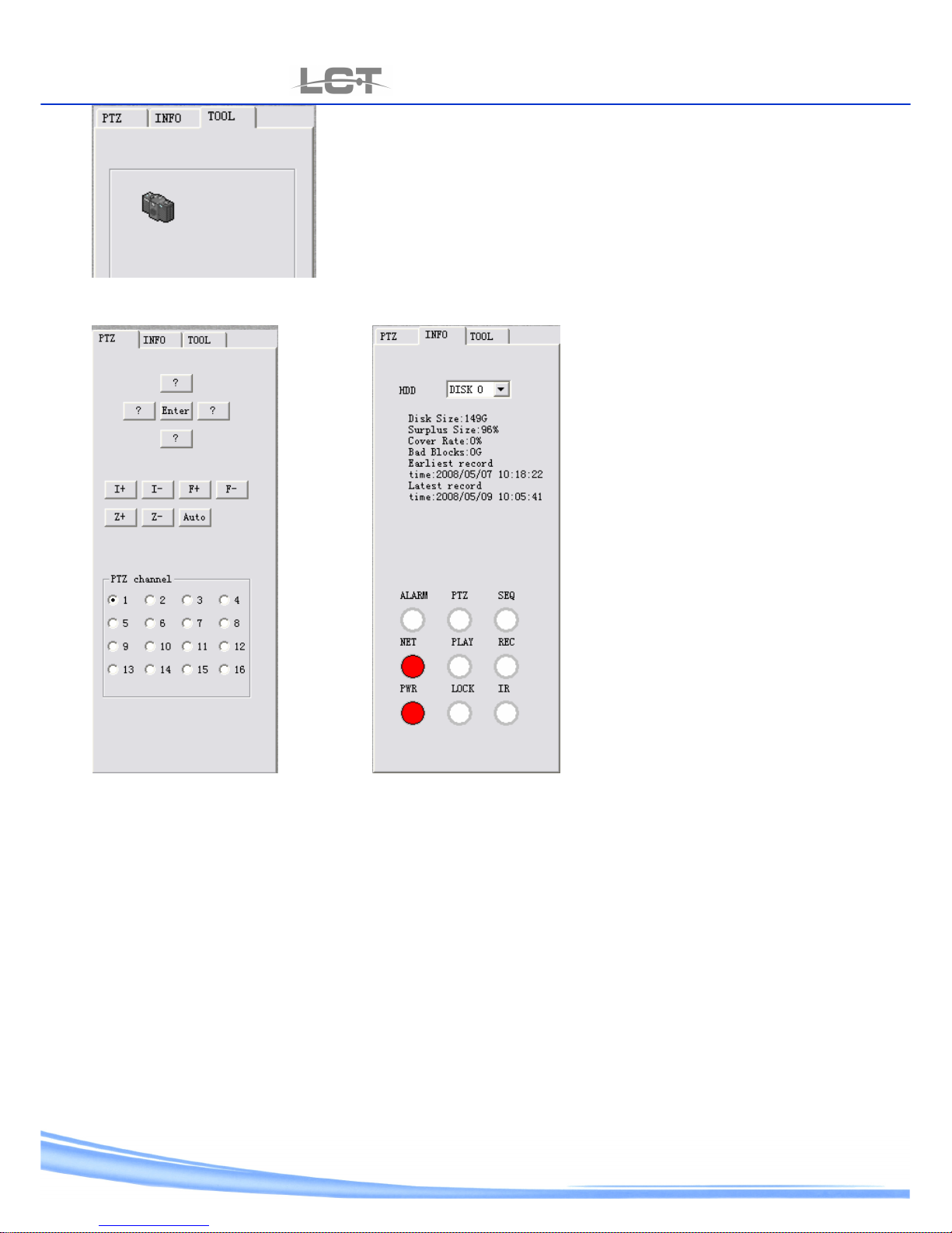
-used PTZ, INFO and TOOL menu to control the speed dome, click the DVR status to get information and shot picture ,as
show of the next shape .
Page 26
USER MANUAL
LCTVR6104-8208-8216
pag.
26
www.hrcctv.com
picture catch instrument.
PTZ instrument INFO instrument
:
5.3 Software anvplayer through connection
Put in the CD-rom software present a dowry provided.
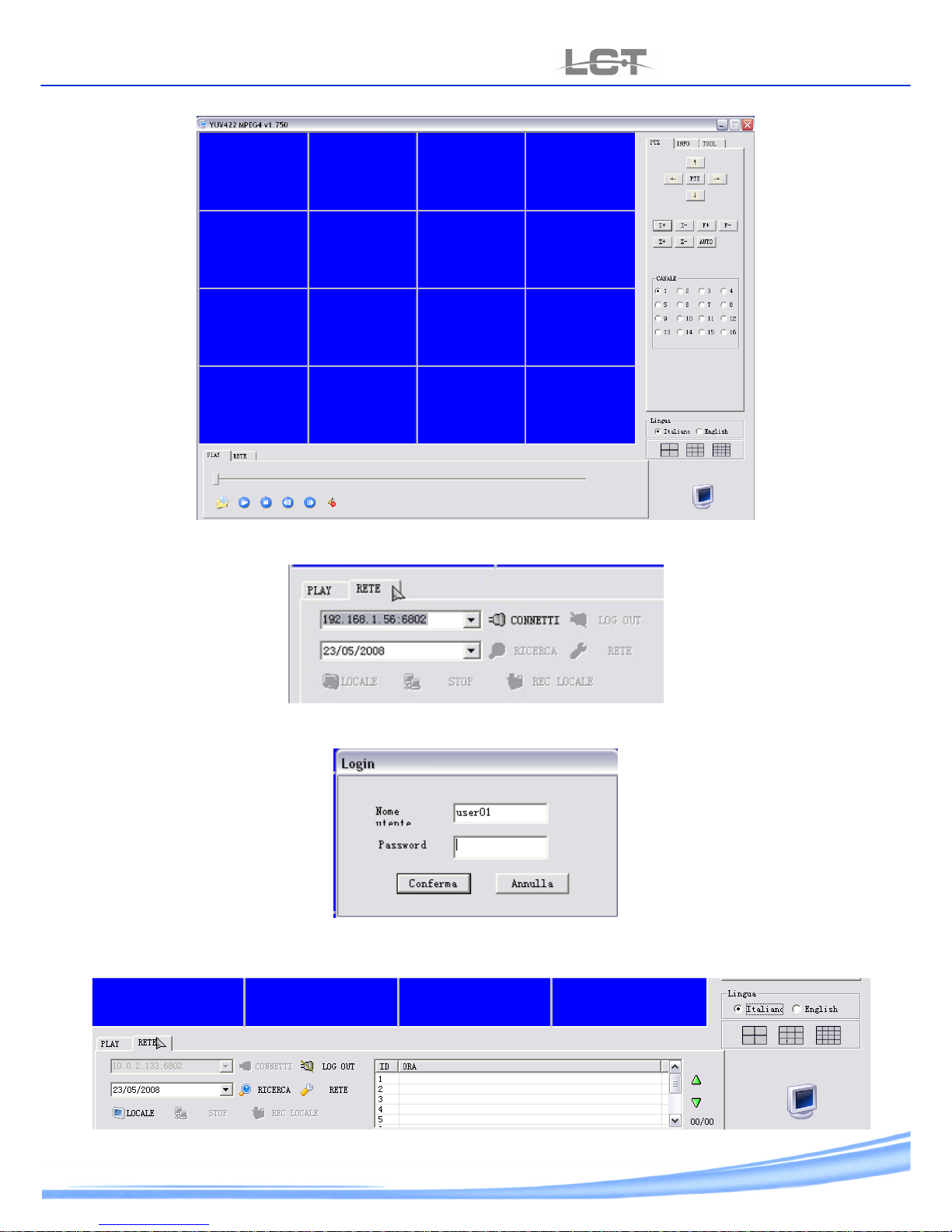
Start the planning and wait for the window as the next screen:
Page 27
USER MANUAL
LCTVR6104-8208-8216
www.hrcctv.com pag.27
Click net and put in the good paramaters for the device connnection.
After to have set up IP address of DVR , click link up and put in user name and authentication password:
After to have make the login , all keys come to set up.
So is possible to use all functionality of software.
Page 28
USER MANUAL
LCTVR6104-8208-8216
pag.
28
www.hrcctv.com
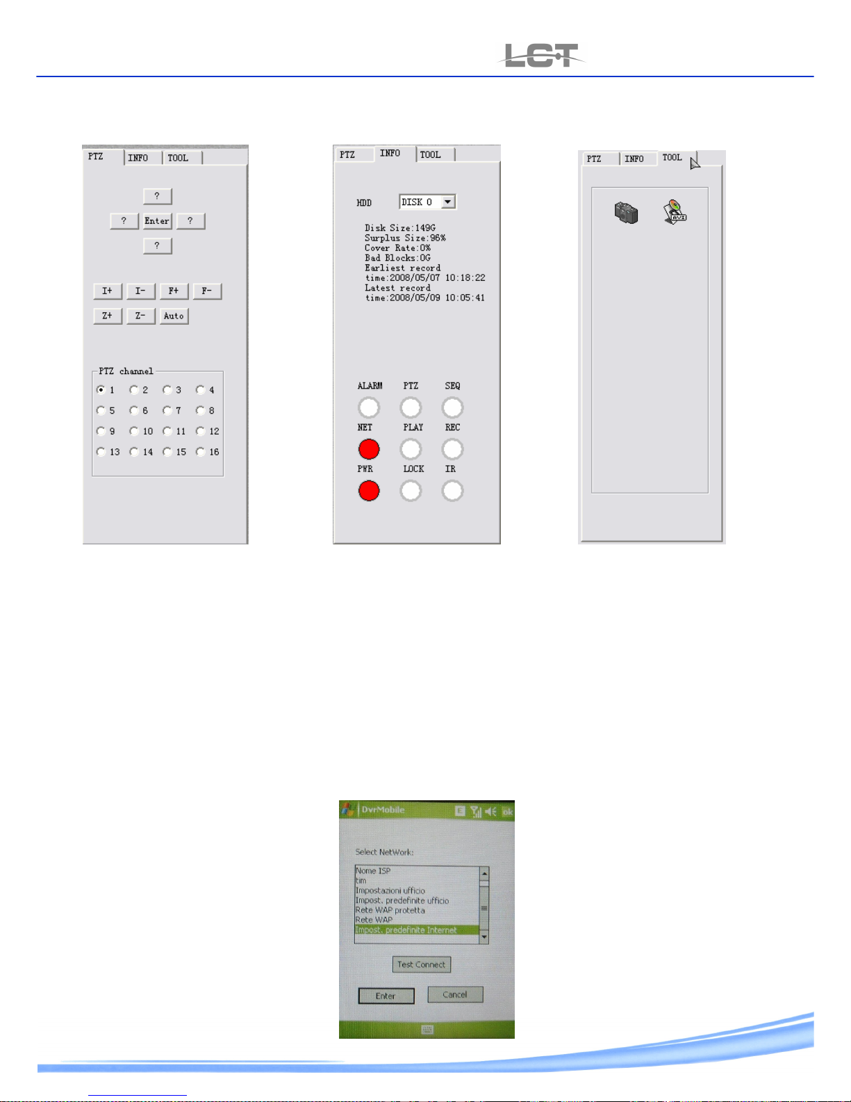
Is possible to make the next operations by means of plain interface:
-Press search to make the search of file to listed in order time by play back .
-Press Local ,to display the Live picture .
-Press Stop to stop the display or local Rec for recording in the teeth of computer.
-for setup the parameters of recording is fundamental to stop the Live display . press net to start the next screen .
-Used PTZ, INFO and TOOL menu to control the speed dome, click the DVR status to get information and shot picture as show
of the next shape .
Page 29
USER MANUAL
LCTVR6104-8208-8216
www.hrcctv.com pag.29
PTZ instrument INFO instrument catch picture instrument and AVI conversion
.
:
N.B. the AVI conversion strument is only turned on LCTVR6104.
5.4 SMART PHONE by means of connection
1.1.1 the least system required:
- MS Windows Mobile endowed smart phone 5.0 or Superior.
- GPRS, EDGE, UMTS connection.
-Display TFT 2,8”.
-in case the DVR public static IP address with ADSL connection
1.1.2 Installation:
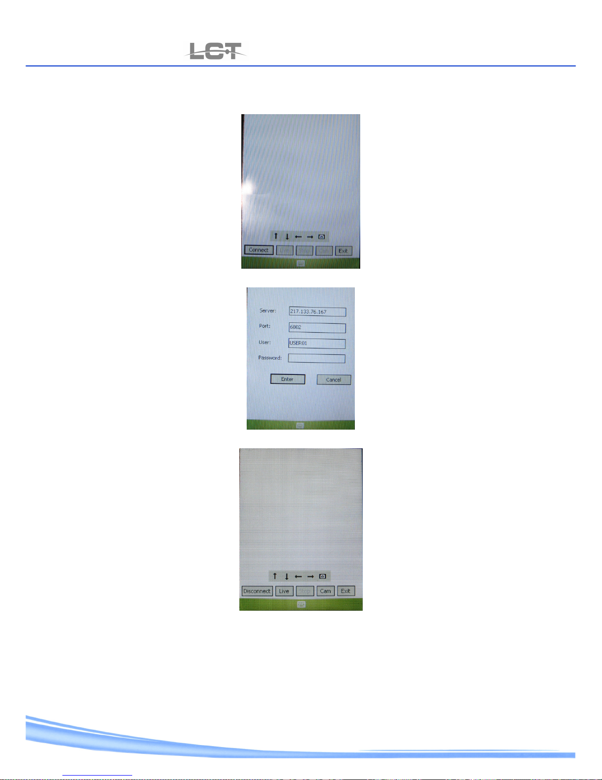
for be able to use the software is necessary start DVR_Mobile.exe package present in CD-Rom at Smart phone wanted to use.
Use the method referring to Vs. phone manual to need link (Bluetooth, IR, Cable, memory card).
Setup the internet really connection ,assure the presence of Vs. administrator pip and start application.
Page 30
USER MANUAL
LCTVR6104-8208-8216
pag.
30
www.hrcctv.com
Select the really connection and press ENTER
Click the Connect
Setup the remote DVR parameters connection give to ISP, the user name and the password and the access port of DVR.
Wait for take place connection:
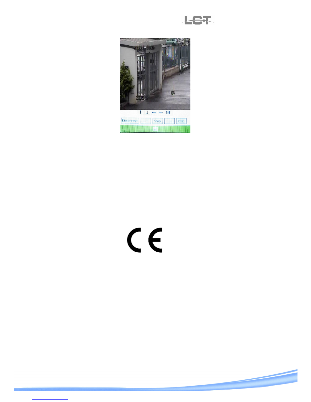
Click CAM to select camera then start LIVE the picture display . for move on the camera in display , click Stop and say again
praxis.
Page 31
USER MANUAL
LCTVR6104-8208-8216
www.hrcctv.com pag.31
Technical specifications can be modified without any preliminary notice
Page 32

USER MANUAL
LCTVR6104-8208-8216
pag.
32
www.hrcctv.com
HR EUROPE s.r.l.
ROMA: sede legale e amministrativa; Via Giulianello, 1-7 – 00178 Roma, ITALIA – Tel +39 06 7612912 Fax +39 06 7612601
TORINO: sede operativa; Via G.B.Feroggio, 10 – 10151 Torino, ITALIA – Tel +39 011 453 53 23 Fax +39 011 453 70 49
SHANGHAI: ufficio di rappresentanza; Minhang Residence, Room 506, N°50 Jinzhu Road 200336 Shanghai, CHINA
Tel(Fax):+86 21 62086781 – e-mail: [email protected]
e-mail: [email protected] web: www.hrcctv.com – Codice Fiscale e Partita IVA 06397551000 – Iscrizione R.E.A. 966880
 Loading...