

Page 1
User manual
Gaming 978BG - Tank-Buster
Page 2

Content
Chapter 1 Product introduction
1.1 Specification.....................................................................................03
1.2 Accessory..........................................................................................04
Chapter 2 Installation guide
2.1 Side panel assembly.............................................................................. 05
2.2 Motherboard installation......................................................................06
2.3 5,25” device installation........................................................................07
2.4 3,5” device installation.....................................................................08-09
2.5 2,5” device installation..........................................................................10
2.6 PSU installation..................................................................................... 11
2.7 Fan installation................................................................................. 12-13
2.8 Water cooling installation................................................................13-14
2.9 Front panel control & I/O installation..............................................14-16
Page 3

Thank you for purchasing the “Gaming 978BG - Tank-Buster” case
from LC-Power. Please read this manual before usage.
Specifications may be subject to change without prior notice.
Chapter 1 Product introduction
1.1 Specification
Dimension 238(w)x 560(h)x 590(d)mm
Material Steel (SECC)
Front & top panel:ABS + meshed designed
5,25” drive bay 4 external
3,5” drive bay 6 internal – HDD cage with hot swap feature
2,5” drive bay 3 internal
PCI slot 9
I/O Panel 2x USB 3.0, 2x USB 2.0, 1x Audio, 1x Mic,
fan speed control for up to 5 fans
Control Panel Power switch, Reset switch, Power LED, HDD LED
Cans fans mounting
options
Front: 2x 120 mm (included in delivery)
Back: 1x 120 mm (included in delivery)
or 1x 140 mm
Top:3x 120 mm
Bottom: 2x 120 mm
Water cooling: support up to 360 mm radiator on
top and up to 240 mm radiator on bottom
Motherboard E-ATX / ATX / Micro-ATX / Mini-ITX
Power Supply ATX standard
Page 4
Compatibility Graphic card up to 340 mm
CPU cooler up to 190 mm
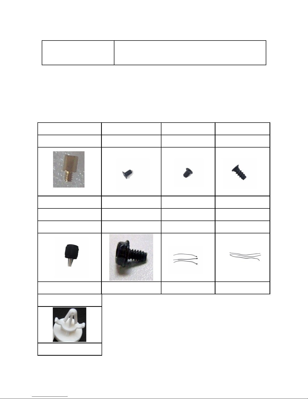
1.2 Accessory
Accessory box contents: 1x user manual, 1x screw bag
Standoff Screw Screw Screw
5H-6#*4- 6#*6.5HCu M3*5 6*5KM 3*8*8PWA
10PCS 20PCS 24PCS 4PCS
Plastic hand screws Screw Cable tie Cable tie
6#-32 6#6HW-TC L=120mm L=150mm
10PCS 4PCS 3PCS 3PCS
Plastic standoff
3PCS
Page 5

Chapter 2 Installation guide
2.1 Side panel assembly
1.
Remove the side panel:
Remove the screws on the back of the chassis and open the side panel.
2.
Reattach the side panel:
Align the side panel with hook holes to close the side panel.
Fix it with screws.
Page 6
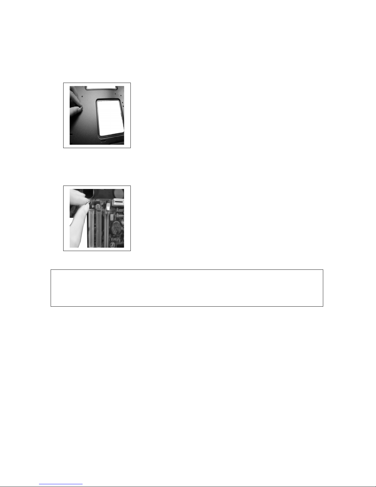
2.2 Motherboard installation
1.
Screw the standoffs on the holes for the motherboard installation bracket.
2. Install the motherboard in a proper location and fix it with the provided
screws.
Note: CPU, RAM and any peripheral installation steps are not included in this manual.
Please refer to your motherboard manual for related mounting instructions .
Page 7

2.3 5,25” device installation
1.
Press the latch to remove the 5,25” drive cover from the chassis by pushing it
inside out. Now put the 5,25” ODD into the drive bay.
2. Fix the 5,25” ODD with the quick release screws on the side.
Page 8

2.4 3,5” device installation
1.
Open the side panel with the help of the latch.
2.
Push the latch of the drive bay and take out the 3,5” drive bay tray.
3.
Place an HDD into the drive bay tray and secure it on the bottom of the tray
with the provided screws. Reverse the above mentioned steps to place the
HDD tray in the device cage.
Page 9

4.
Connect the backplane with a 4 pin Molex/PATA connector of the power
supply.
Connect the backplane to the motherboard with the help of SATA cables.
Note: The user may choose the direction of the 3,5” drive cage. This
will help the user to arrange the chassis placement flexibly. Please
refer to the pictures below for the further information.
Page 10

2.5 2,5” device installation
Gaming 978BG provides three positions for the 2,5” HDD/SSD installation.
Two HDDs/SSDs on the side of the 5,25” drive cage and one HDD/SSD under the
3,5” HDD cage location.
1.
Open the side panel with the help of the latch.
2.
Place the 2,5” HDD/SSD in a proper location as shown below and fix it with
the provided screws.
3.
For the third position, release the screw on top of the 3,5” HDD cage and
remove it. Put the 2,5” HDD/SSD on the bottom side of the bracket as shown
below and secure the HDD/SSD with the provided screws.
Page 11

2.6 PSU installation
1.
Place the PSU in a proper location and fix it with the provided screws.
(Screw holes enable a PSU mounting from both sides; fan up or down)
2. Place the power supply cables behind the mainboard tray.
3. To clean the dust filter, pull out the washable dust filter which is placed under
the power supply location.
Page 12

2.7 Fan installation
Bottom fan installation
1. Remove 6 screws as shown below and then remove the bottom bracket.
2. Install the fan inside the chassis and secure the screws from the bottom side.
You can install maximum two 120 mm fans on the bottom panel.
Top panel fan installation
1. Remove the screws on the back side of chassis and open the top panel.
Page 13

2. Install the fans on the top of the case and use screws to fix them to the
matching holes.
You can install maximum three 120 mm or two 140 mm fans on the top of the
chassis.
2.8 Water cooling installation
On
the back side of the case you will find pre-drilled water cooling holes.
Screw holes are drilled on the top of the chassis to fix a 360 mm radiator.
On the bottom panel, you can fix a 240 mm radiator.
Page 14

2.9 Front panel control & I/O installation
Please refer to the following table for front panel control & I/O ports.
Item Description Item Description
1 Power on/off 2 Reset
3 Fan speed control +/- 4 Power LED
5 HDD activity LED 6 Fan speed LED
7 USB 3.0 port 8 USB 2.0 port
9 Audio & mic
The chassis provides a “fan speed control feature” which supports up to 5
case fans. Press the “+”-symbol to accelerate and the “-“-symbol to slow
down the case fan speed.
The feature provides four sections to control fan speed from 40% to 100%.
The LED light will be turned on by corresponding fan speed. Please refer to
1
2
3
4
5
6
7
8
9
Page 15

the following step to install the case fan.
1. Connect a 4 pin Molex/PATA connector from PSU
2. Remove the top cover and connect the 3-pin fan connectors to the
control board.
Please refer to the following illustration of the front I/O connectors and your
motherboard user manual.
Page 16

Front I/O Connector
Motherboard Case cable connector
USB 3.0
USB 2.0
AC’97
HD Audio
Page 17

The product has a two year warranty period from the date of purchase,
service issues will be handled by your dealer.
If the case is damaged due to improper operation, the warranty period expires
immediately.
Check www.lc-power.com or contact us by e-mail at support@lc-power.com.
Silent Power Electronics GmbH
Mühlenstr. 123
Gewerbegebiet West
41352 Korschenbroich
Germany
 Loading...