

LCO Technologies CROSSFIRE Installation And Operation Manual
The CROSSFIRE
Ultra-Low Power Instrument Air Compressor
Installation and Operations Manual

CROSSFIRE Installation & Operations Manual
2 | P a g e
© 2018, LCO Technologies LTD. All rights reserved.
Table of Contents
CSA Requirements and Installation Requirements ................................................................................ 3
CROSSFIRE Installation Guide ............................................................................................................. 7
CROSSFIRE Compressor Start Up ...................................................................................................... 11
Software Interface Guide ..................................................................................................................... 12
Interface Overview ........................................................................................................................... 12
Main menu ....................................................................................................................................... 13
Connect to Controller: ...................................................................................................................... 13
Disconnect from Controller: .............................................................................................................. 13
Configuration Panel – Operator configuration ................................................................................... 14
Motor Control Panel ......................................................................................................................... 15
Configuration Panel – System setup ................................................................................................ 16
Configuration Panel – I/O config ....................................................................................................... 18
Configuration Panel – Advanced Automation ................................................................................... 19
Configuration Panel – Terminal ............................................................................................................ 20
Configuration Panel – System status ................................................................................................ 21
Possible Fault Codes ....................................................................................................................... 22
Controller Troubleshooting ............................................................................................................... 24
CROSSFIRE Maintenance .................................................................................................................. 26
CROSSFIRE Technical Drawings ........................................................................................................ 28
Assembled CROSSFIRE Instrument Air Compressor with Fan Cover: ............................................. 28
Assembled CROSSFIRE Instrument Air Compressor with No Fan Cover: ....................................... 29
LCO-COMP Top Works Replacement Kit: ........................................................................................ 30
CROSSFIRE Compressor Troubleshooting ......................................................................................... 31
CROSSFIRE Return and Repairs ........................................................................................................ 34
Repairs............................................................................................................................................. 34
Return Procedure ............................................................................................................................. 34

CROSSFIRE Installation & Operations Manual
3 | P a g e
© 2018, LCO Technologies LTD. All rights reserved.
CSA Requirements and Installation Requirements
IMPORTANT SAFETY CONSIDERATIONS
WARNING
AVERTISSEMENT
EXPLOSION HAZARD - SUBSTITUTION OF COMPONENTS
MAY IMPAIR SUITABILITY FOR INSTALLATION IN HAZARDOUS LOCATIONS
RISQUE D'EXPLOSION - LA SUBSTITUTION DE COMPOSANTS
PEUT RENDRE CE MATÉRIEL INACCEPTABLE POUR LES
EMPLACEMENTS DANS DES ENDROITS DANGEREUX (CLASSE 1, DIVISION 2).
WARNING
AVERTISSEMENT
EXPLOSION HAZARD - DO NOT REPLACE COMPONENTS
UNLESS POWER HAS BEEN SWITCHED OFF OR THE AREA IS
KNOWN TO BE NON-HAZARDOUS.
RISQUE D'EXPLOSION - COUPER LE COURANT OU
S'ASSURER QUE L'EMPLACEMENT EST DÉSIGNÉ NON
DANGEREUX AVANT DE REMPLACER DES COMPOSANTS.
WARNING
AVERTISSEMENT
EXPLOSION HAZARD - DO NOT CONNECT OR DISCONNECT EQUIPMENT
UNLESS POWER HAS BEEN SWITCHED OFF OR THE AREA IS
KNOWN TO BE NON-HAZARDOUS.
RISQUE D'EXPLOSION - AVANT DE DÉBRANCHER
L'ÉQUIPEMENT, COUPER LE COURANT OU S'ASSURER
QUEL'EMPLACEMENT EST DÉSIGNÉ NON DANGEREUX
WARNING
AVERTISSEMENT
THE CONTROLLER ASSEMBLY IS FOR USE IN CLASS I, DIVISION 2, GROUPS C AND D, AND OR
NONHAZARDOUS LOCATIONS ONLY.
L’APPAREIL DU CONTRÔLEUR CONVIENT À L’UTILISATION DANS LES EMPLACEMENTS
DE CLASSE 1, DIVISION 2, GROUPES C ET D, OU NE CONVIENT
QU’A L’UTILISATION DANS DES EMPLACEMENTS DÉSIGNÉS NON DANGEREUX.
WARNING
AVERTISSEMENT
THE MOTOR ASSEMBLY IS FOR USE IN CLASS I, DIVISION 1, GROUPS C AND D, AND OR
NONHAZARDOUS LOCATIONS ONLY.
L’APPAREIL DU MOTEUR CONVIENT À L’UTILISATION DANS LES EMPLACEMENTS
DE CLASSE 1, DIVISION 1, GROUPES C ET D, OU NE CONVIENT
QU’A L’UTILISATION DANS DES EMPLACEMENTS DÉSIGNÉS NON DANGEREUX.

CROSSFIRE Installation & Operations Manual
4 | P a g e
© 2018, LCO Technologies LTD. All rights reserved.
AGENCY
CERTIFICATION
Controller Assembly
(Must be placed in a Cabinet/Enclosure that provides a minimum Ingress Protection of NEMA
4/IP54)
Class 1, Division 2, Groups C and D, or nonhazardous.
Temperature Code: T4, Tamb: -40 to 60 Deg. C.
Suitable for Zone 2, IIB.
Motor Assembly
(Motor is for indoor or protected environment use only)1
Class 1, Division 1, Groups C and D, or nonhazardous.
Temperature Code: T6, Tamb: -40 to 60 Deg. C.
Suitable for Zone 1, IIB.
Models:
Explosion Proof Motor Assembly Model LCOM-1000
Controller Model LCOC-1000-A and Model LCOC-1000-B
IMPORTANT: Conditions of Certification
✓ The Controller must be installed within an enclosure suitable for the environment and requiring a
tool or key to open. Controller models LCOC-1000-A and LCOC-1000-B are intended for use in
a Pollution Degree 2 environment.
✓ The RS232 connector must be retained with two screws on the mating connector.
✓ The Ethernet RJ45 connector must be retained with its original locking tab to withstand a 15
Newton pull force once engaged.
✓ Model LCOM-1000 and Model LCOC-1000 must be used together to form a Certified Brushless
DC (BLDC) Motor System. No substitutions of motor types are permitted.
Controller
The controller input voltage rating is 24 VDC. The battery power supply must be capable of supplying
24 VDC to ensure reliable operation and motor start-up. For average current draw based on application
and help with solar sizing, please contact LCO Technologies directly. Current draw on most
applications in steady state is around 0.7-2.0 A, however the rated maximum current draw for the
controller is 9.9A.
The Controller must be protected by external over current protection in keeping with CEC and NEC
practices supplied at the time of installation.
1
Note: Protected environment means the motor must be under a shelter and off the ground to protect the motor
from moisture (such as rain, snow, ice etc.)
CROSSFIRE Installation & Operations Manual
5 | P a g e
© 2018, LCO Technologies LTD. All rights reserved.
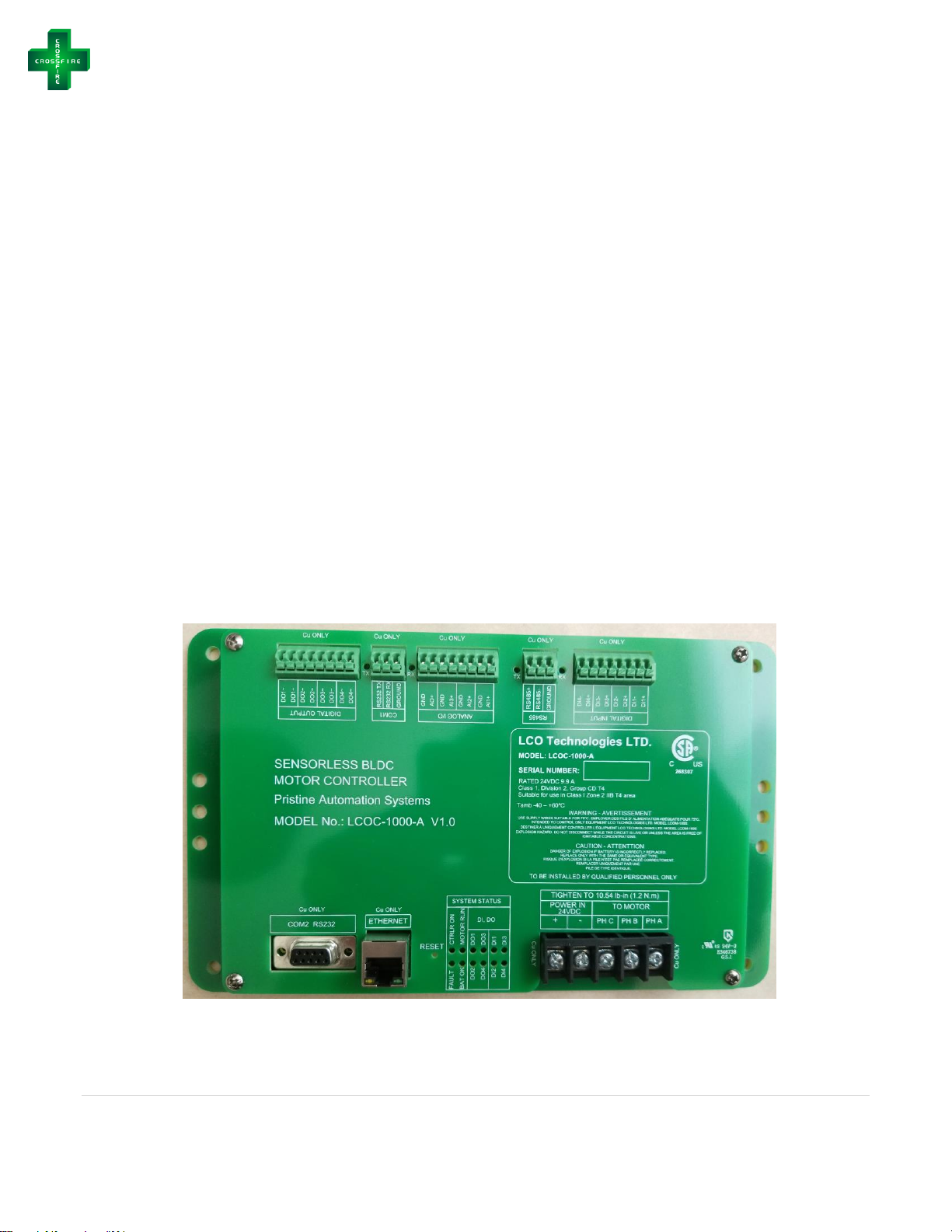
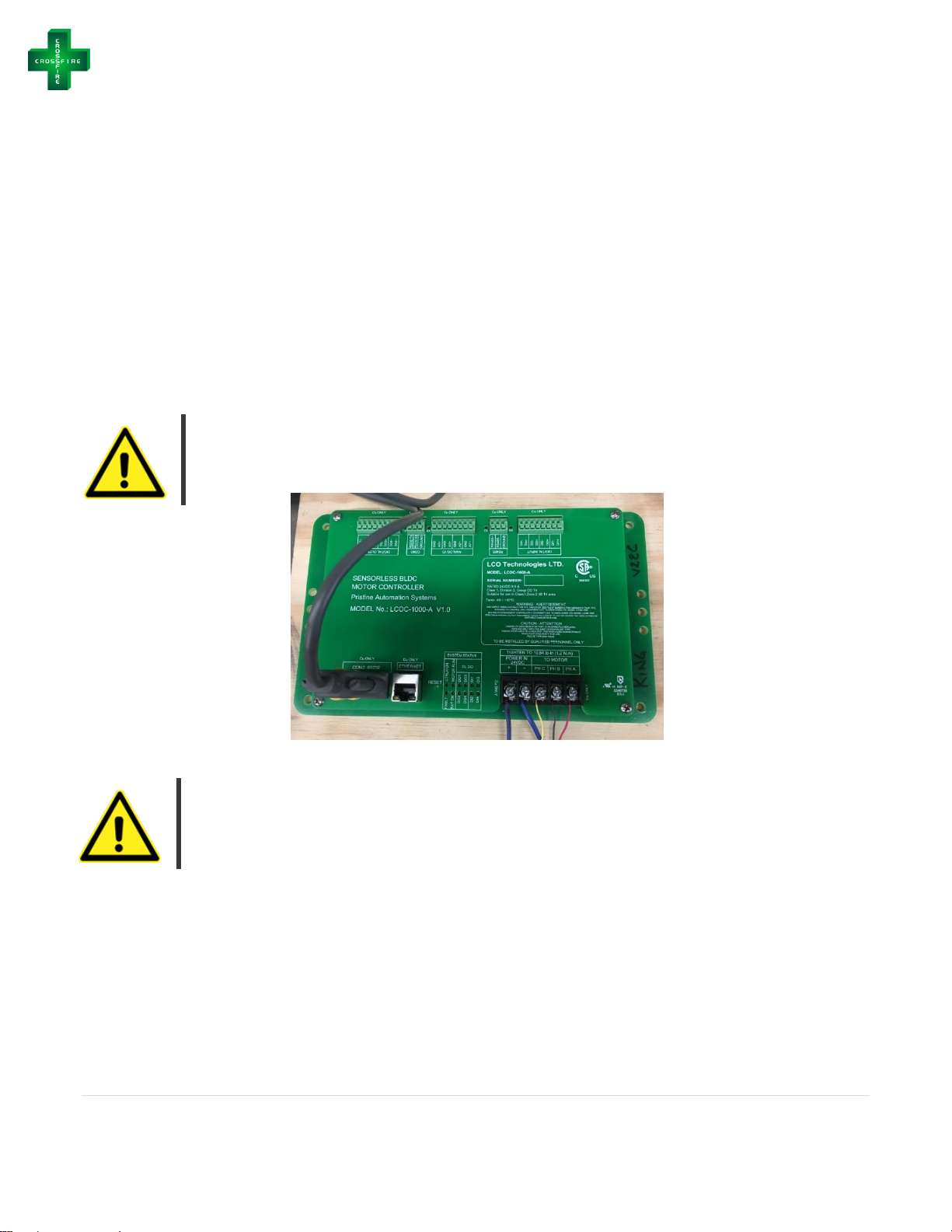
EXTERNAL CONNECTORS
The controller features several external connectors. These are labelled as followed:
• Power In: Connectors are used to connect the 24VDC power supply.
• To Motor: Connectors are used for Phase A, Phase B and Phase C of BLDC. These
connections are not phase sensitive.
Use only copper conductors on supply and motor load terminal blocks
“TIGHTEN TO 10.54 pound-inches (1.2 N•m)”. Or Equivalent
It is a CSA requirement to use #10 straight or ring lugs with 10 - 12 AWG wiring, when connecting to
the Power and Motor connectors. The Controller data connectors can accept 22 to 24 AWG stranded
wire.
All wiring and connections must be in line with accepted wiring practices as outlined by the Canadian
Electrical Code (Canada) and the National Electrical Code (USA) and installed by qualified personnel
only (use copper conductors only.)
There are two patterns of mounting holes on the Controller unit. The four corner mounting positions are
for a direct fastening to the enclosure using # 6 screws. The two patterns of 3 holes are for DIN Rail
mounting brackets. Installer must supply screws and brackets as applicable.
CROSSFIRE Installation & Operations Manual
6 | P a g e
© 2018, LCO Technologies LTD. All rights reserved.
Motor
Accurate mechanical lineup is essential for successful operation. Mechanical vibration and roughness
in running the motor may be an indication of poor alignment. It is recommended that the lineup be
checked when installed.
For direct coupled applications, use flexible couplings when possible. Use of a sealed fitting at the
motor wiring entrance point is required with a minimum of 5 full thread engagement to maintain the
Class I, Division1 rating of the motor when installed in a Hazardous Area.
The 3-Phase conductors and the Earth ground must be terminated in an approved Class I, Division 1
junction box. The green Earth lead must be grounded to the ground screw in the junction box.
WARNING: Motor, Control and Grounding must be in accordance with Canada - Canadian Electrical Code
and/or USA – National Electrical Code and consistent with Local requirements and practices. Use
Ground lug on exterior of Motor enclosure and Ground lead provided to ensure proper Grounding of the
Motor.
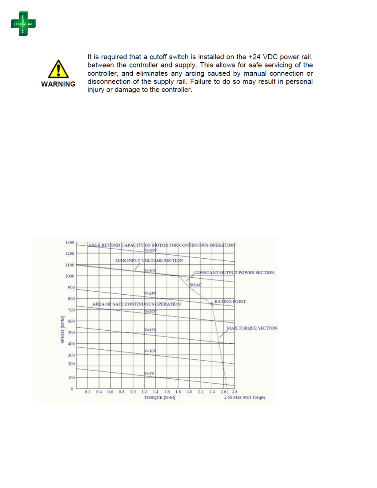
See below for Safe Operating Area Curves (SOAC) for the Motor
Figure 1: Safe Operating Area Curves (SOAC)
CROSSFIRE Installation & Operations Manual
7 | P a g e
© 2018, LCO Technologies LTD. All rights reserved.
CROSSFIRE Installation Guide
Step 1: Open Shipment
− Confirm the following parts are present
o LCOD-COMPRESSOR Package
▪ LCOD-Compressor mounted on an accumulator volume bottle, complete with
pressure transmitter and other accessories ordered
▪ Complete with tubing from the compressor to the accumulator volume bottle
o Smart Controller: Part Number # LCOC-1000-B
▪ Shipped loose or pre-installed in a C1D2 panel as per customer requirement
− Check to ensure no parts were damaged during shipment
o Contact the shipment carrier and file a claim if any damage has been identified
o If replacement parts are required, please contact your supplier
− Familiarize yourself with all parts and pieces
Step 2: Mount the compressor
− Find a desired location for installation
o A location that can accommodate compressor package dimensions
o Ensure the compressor is in a protected environment and out of the elements
▪ For example, inside the skid building
o Avoid direct exposure to catalytic heaters if present in the building
▪ The compressor generates its own heat and will run more efficiently when cool
o Install near the utility gas distribution system
− Set the compressor package down
o Recommendation: Secure the compressor package to the floor; use prefabricated holes
in the base frame to bolt down or weld to attach materials
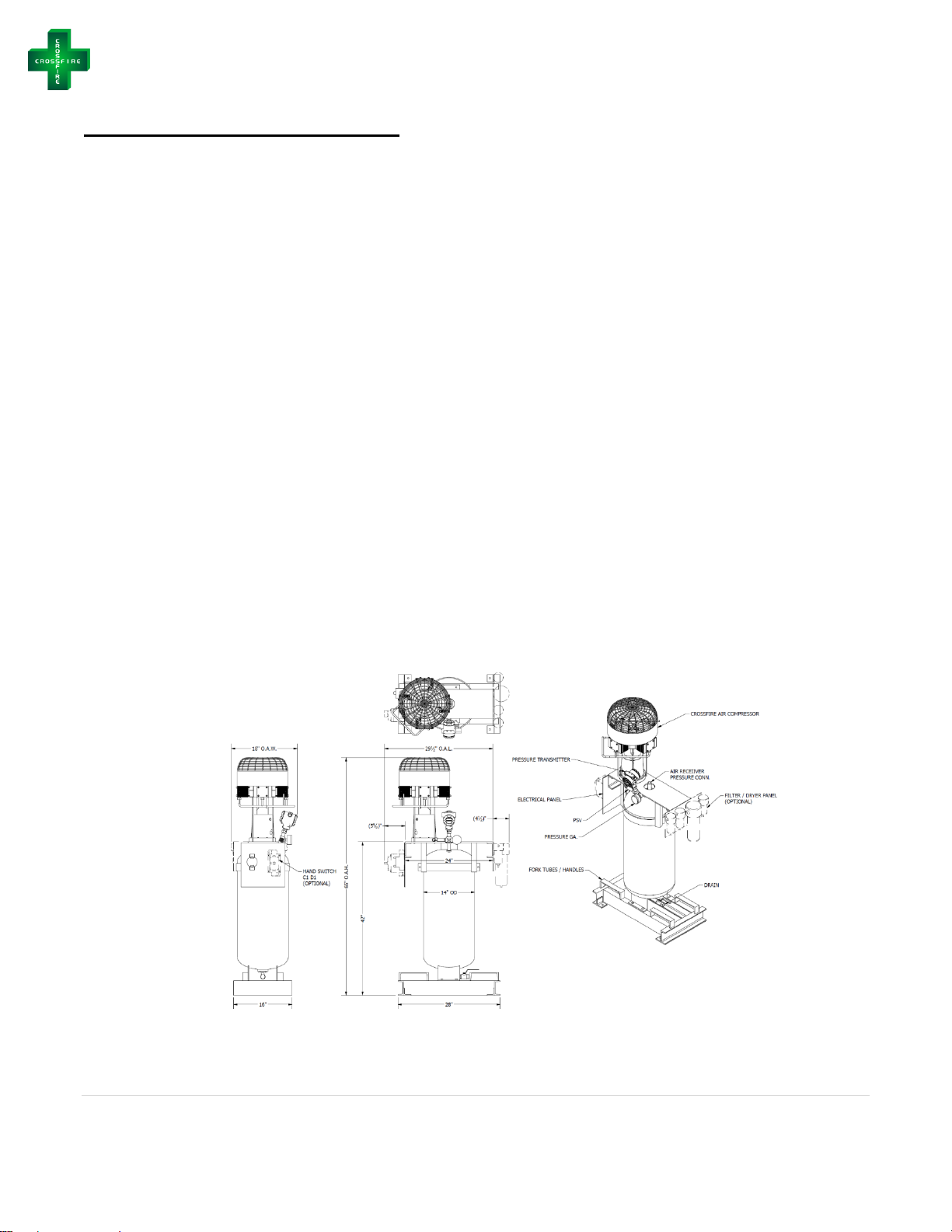
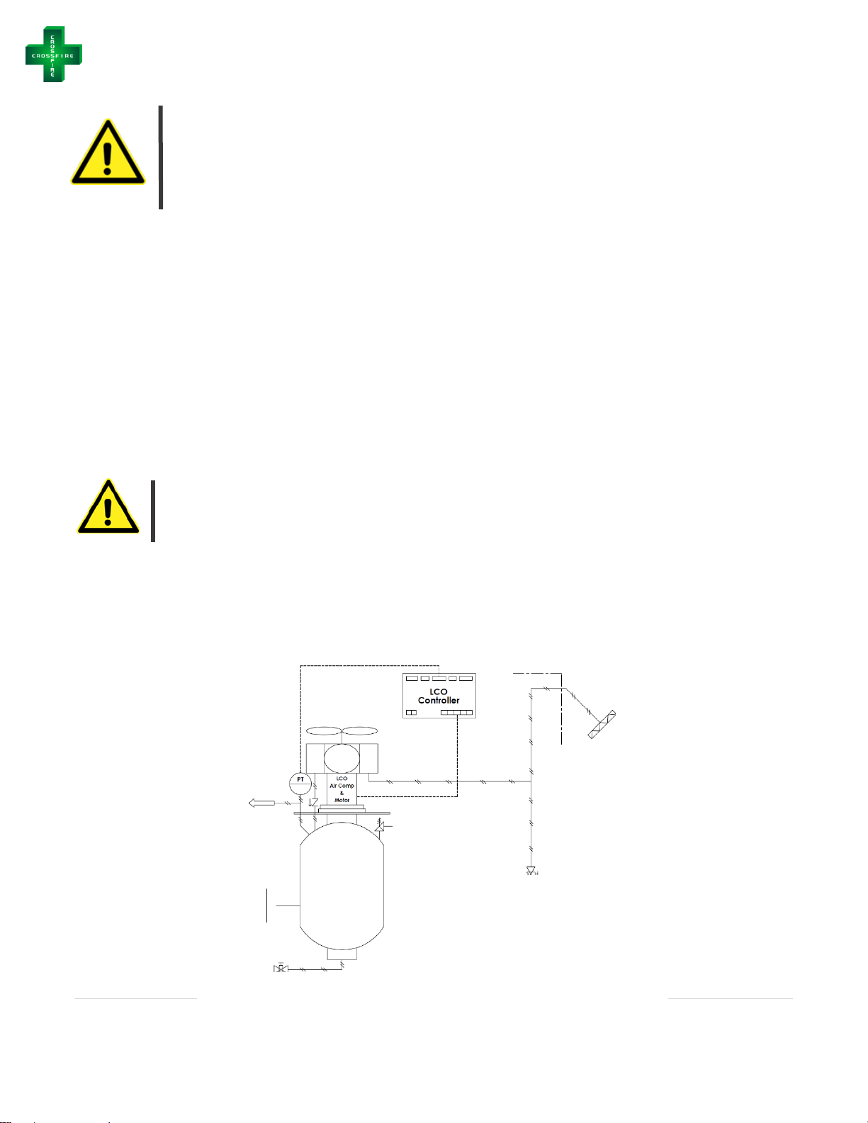
Figure 2: CROSSFIRE Compressor Package
CROSSFIRE Installation & Operations Manual
8 | P a g e
© 2018, LCO Technologies LTD. All rights reserved.
Warning: The Compressor is mounted and attached on top of the air accumulator
volume bottle to ensure any moisture present at discharge flows into the accumulator
and not back towards the compressor valves. In addition, the tubing from the
compressor outlet to the accumulator is completed already to ensure moisture can easily
drain. Do not adjust this set up or configuration. Any modifications may affect
compressor performance and will impact product warranty.
Step 3: Tube the compressor
− Remove the air filter and female connector fitting (PFC-06-08-SS) from the LCOD-Compressor
inlet
o Keep the filter attached to the PFC-06-08-SS
− Tube the attached filter and PFC-06-08-SS outside the skid building
o Tube the filter out the top of the building so it is outside of the C1D1 environment
▪ Confirm the air intake is from a fresh air source and located away from any fuel
gas or combustible gas lines that may be venting
o Ensure the filter is under the building overhang to protect from rain or snow
accumulation
o Face the filter downwards at a 45-degree angle.
Warning: Filter must be protected from rain and snow accumulation and installed at a 45degree angle. If insufficient cover from building overhang, water and liquids will be
introduced to the compressor and may affect compressor performance.
− Tube a “dirt pocket” into the system in between the filter and the compressor inlet to allow for
dirt and moisture capture. Attach a ball valve or mini valve or solenoid or back pressure
regulator for control.
− Tube a “dirt pocket” on the accumulator tank outlet and then tube to instruments
Tube provided filter for
the compressor inlet
above and outside of
the building at a 45-
degree angle
Figure 3: CROSSFIRE Compressor Installation P&ID
4-20 mA or 0-5 V Output
Supplied
Relief
Valve
Dirt Pocket
Dirt Pocket
Tube Air Output to
Instrument Header
(Regulate if
Required)
Accumulator
Bottle
CROSSFIRE Installation & Operations Manual
9 | P a g e
© 2018, LCO Technologies LTD. All rights reserved.
Step 4: Install the Smart Controller (LCOC-1000-B)
− Mount the Controller in a Nema 4 Enclosure as per CSA requirements (page 2 to 6)
− Wire the controller to a 24 VDC power supply
o Connect the 2 conductors, 10 gauge tech cables with appropriate environmental and
classification seals to the controller
− Attach the three conductor cables from the motor to the controller. The green ground wire can
be terminated at any ground. The conductor cables must be terminated in a Class 1, Division 1
junction box at the motor.
o The three conductor cables will be terminated in the controller at termination points
marked phase A, phase B, and phase C (PH A, PH B, PH C)
o The wires must be attached in a specific order to ensure the fan spins in the correct
direction. Attach the red wire to PH A, the black wire to PH B, and the yellow wire to
PH C.
o Cables are gauge 10 and can be a maximum length of 60 ft
Warning: If the resistance in the gauge 10 wires does not meet AWG standards, the
distance must be reduced proportionately.
Warning: All conductor cables must be attached with proper end ferrule connectors and
clamped down properly with the appropriate tools. Double check that all screw terminals
are tightened down to avoid any electrical connection issues. Similarly, if two wires must
be spliced together, please use a proper splicer connector, clamp down sufficiently, and
do not use electrician twist caps.
Step 5: Install Pressure Transmitter
− A pressure transmitter is already installed on the volume accumulator bottle with the
compressor package. This transmitter allows the CROSSFIRE smart controller to automatically
control the motor speed to maintain a set pressure in the accumulator bottle to maximize energy
efficiency
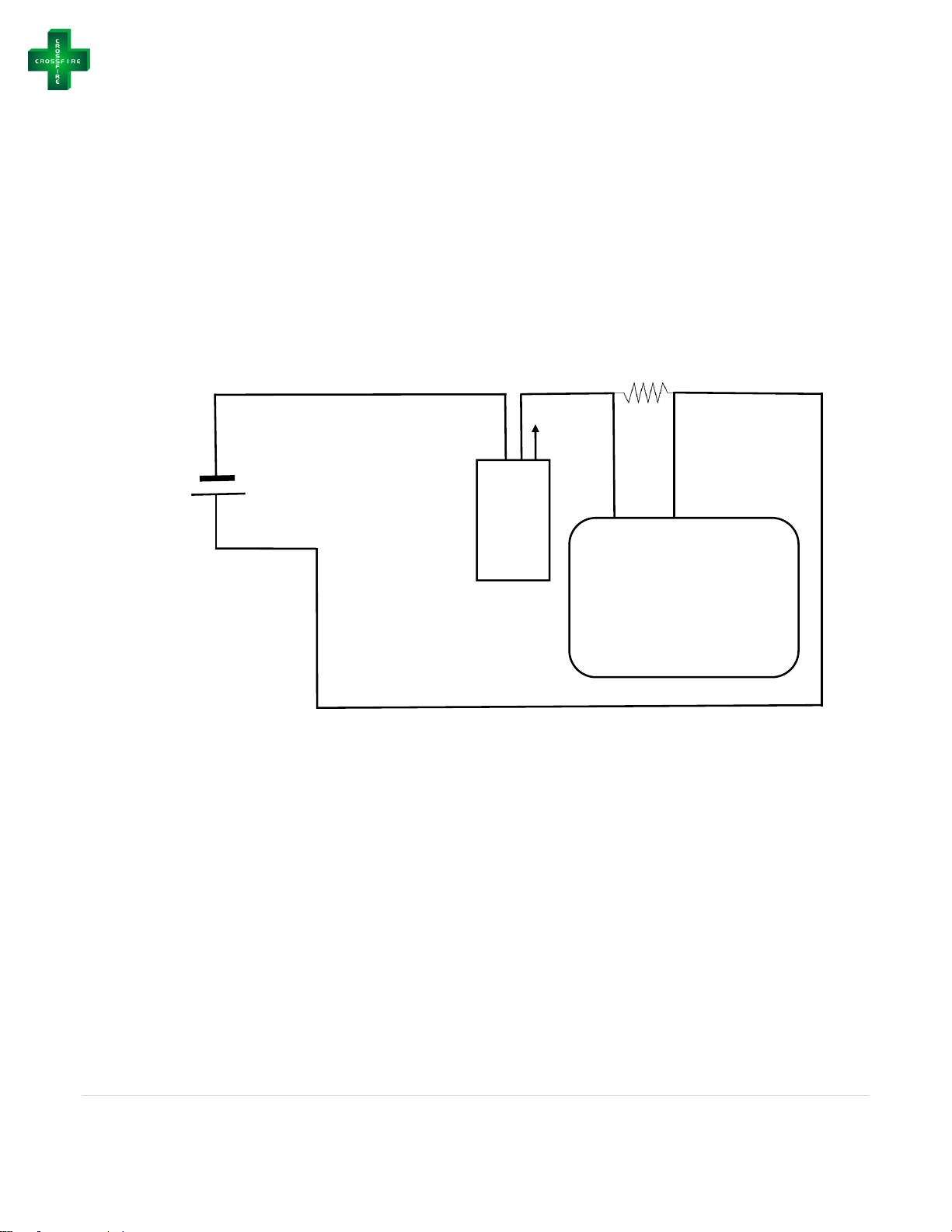
− Wire in your pressure transmitter to the AI1 port on the CROSSFIRE smart controller according
to the wiring diagrams below
o Use Gauge 20-22 AWG Tech Cable for the AI1 Terminal
CROSSFIRE Installation & Operations Manual
10 | P a g e
© 2018, LCO Technologies LTD. All rights reserved.
250 Ohm
Resistor
Pressure
Transmitter
0-50 PSI
4-20mA
AI1+
GND
CROSSFIRE Controller
(LCOC-1000-A or LCOC-1000-B)
Red
Black
24 V
-
+
Green
Note: Wiring diagrams are designed for the pressure transmitter that comes standard with the
Compressor Package (Rosemount 2088). Diagrams may be applied to other models requested outside
of the package, however LCO Technologies does not guarantee this. The use of other models may
affect compressor performance and is not recommended without the consultation of LCO Technologies.
Note: Please use Gauge 20, single strand wires for all terminals on the smart controller.
Figure 4: Wiring Diagram for 0-50 PSI, 4-20 mA Pressure Transmitter
CROSSFIRE Installation & Operations Manual
11 | P a g e
© 2018, LCO Technologies LTD. All rights reserved.
CROSSFIRE Compressor Start Up
Step 1: Download the configuration software
− Go to www.lcotechnologies.com
− Click on the resources tab
− Click on download button and follow all prompted instructions
− ZIP file password: crossfire2017
− The Interface is compatible with the following operating systems:
o Windows XP (32-bit)
o Windows 7
o Windows 8.1
o Windows 10
− Both the operator and technician tabs are password protected.
o Operator Password: Pristine
o Technician Password: Automation
− Note: When using the Mobile Android or Apple App, the passwords are as follows:
o Operator Password: Pristine
o Technician Password: Automatio
Step 2: Start the Compressor
− Connect an RS 232 cable to the controller and computer
− Ensure the acrylic top plate and fan enclosure are on the compressor
− Start up the compressor as per the operator interface instructions listed on page 13.
o Select proportional control mode “36 psi” or “50 psi” based on your application
Warning: Pinch Hazard. Always keep the clear acrylic top plate and the fan cover on the
unit while the compressor is running
Step 3: Observe proper scaling of the pressure transmitter
− Once the compressor is running, isolate the instrument air distribution system and allow the
pressure in the accumulator tank to climb to the set maximum pressure.
o As the pressure increases, the motor speed will decrease
− Open all valves connecting the compressor to the instruments on site and allow compressed air
to flow throughout the system.
− As instruments use the pressurized air, the compressor will automatically modulate the motor
speed up and down to maintain the set pressure in the accumulator bottle.
Optional Step – MODBUS Communications: The CROSSFIRE Compressor can be connected to a
local SCADA/RTU System and communicate via MODBUS. Consult LCO Technologies for the latest
MODBUS maps and for further instructions on integration.
 Loading...