


User Manual
Model HA2401-XI-325X
FCC ID: MYF-XI-325X
IC: 2837A- XI-325X
Interference Statement
This device complies with Part 15 of the FCC Rules and with RSS-210 of Industry Canada.
Operation is subject to the following two conditions: (1) this device may not cause harmful
interference, and (2) this device must accept any interference received, including interference
that may cause undesired operation.
Warning: Changes or modifications not expressively approved by the party responsible
for compliance could void the user’s authority to operate the equipment.
The term “IC:” before the radio certification number only signifies that Industry Canada
technical specifications were met.
NOTE: This system must be installed by experienced professional installers who are
familiar with radio frequency (RF) equipment operation as well as local building and
safety codes. Failure to do so may void the Product Warranty, as well as expose the enduser to legal and/or financial liabilities.
Information to the user
NOTE: This equipment has been tested and found to comply with the limits for a Class
B digital device, pursuant to Part 15 of the FCC Rules. These limits are designed to
provide reasonable protection against harmful interference in a residential installation.
This equipment generates, uses, and can radiate radio frequency energy. If not
installed and used in accordance with the instructions, it may cause harmful
interference to radio communications. However, there is no guarantee that
interference will not occur in a particular installation. If this equipment does cause
harmful interference to radio or television reception, which can be determined by
turning the equipment off and on, the user is encouraged to try and correct the
interference by one or more of the following measures:
Reorient or relocate the receiving antenna.
Increase the distance between the equipment and the receiver.
Connect the equipment to an outlet on a circuit different from that to which the receiver
is connected.
Consult the dealer or an experienced radio/TV technician for help.

Any changes or modifications of equipment not expressly approved by the
manufacturer could void the user’s authority to operate the equipment and the
company’s warranty.
NOTE: Certain high gain antennas are intended for point-to-point or point-tomultipoint applications only. These antennas are clearly identified in the table
contained in this manual. Note that +36 dBi may only be exceeded for point-topoint applications as given in 15.247(b). It is the installers responsibility that
when using these antennas to ensure that the system is used exclusively for
point-to-point operations, and that the antenna may not be co-located with other
intentional radiators transmitting the same information". The device and its
antenna and must not be co-located or operating in conjunction with any other
antenna or transmitter.
The table contained in this manual identifies which antennas are considered
“fixed” and which are “mobile”. When this device is installed as a fixed-mount
application there is a minimum required separation distance of 100 cm between
the antenna and all persons during normal operation. All mobile antennas must
be mounted at a minimum distance of 20 cm from users.
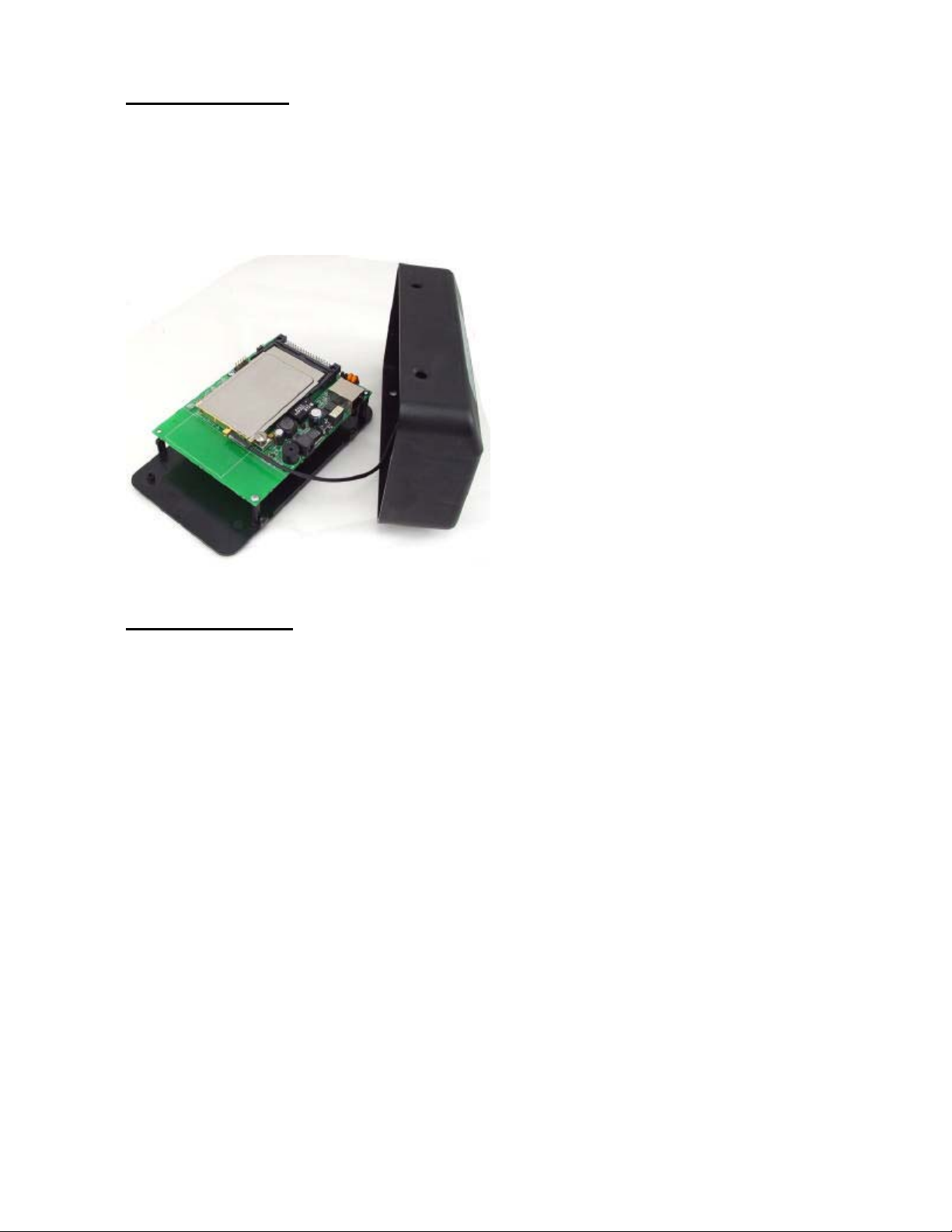
Router Installation:
Conduct a Site Survey to determine the best location for the system. Once located,
install the Router in an appropriate location. Follow the Router mounting instructions
for specific mounting details.
Open the access cover by depressing the two tabs. Slide the PC Card into the PC
Card Slot and plug in the pigtail cable as shown. Then replace the access cover:
Connect the Pigtail Cable between the PC Card and the Amplifier/DC Injector input.
Install the Antenna
NOTE: The antenna system shall be installed ONLY by experienced antenna
installers who are familiar with local building and safety codes, and wherever
necessary have been licensed by appropriate government regulatory bodies.
Failure to do so may void the Product Warranty, as well as expose the end-user
to legal and/or financial liabilities. Hyperlink Technologies, its agents, resellers
or distributors, are not liable for injury, damage, or violation of government
regulations that may arise from failing to comply with the guidelines described
in this document.
Mount the antenna according to the specific installation instructions for the model you
are installing. When choosing the antenna site you must observe the following
exposure limits:
The table contained in Appendix B of this manual identifies which antennas are
considered “fixed” and which are “mobile”. When this device is installed as a
fixed-mount application there is a minimum required separation distance of one
100 cm between the antenna and all persons during normal operation. All
mobile antennas must be mounted at a minimum distance of 20 cm from users.
Once the antenna is installed connect the antenna to the amplifier using the antenna
cable.
Configuring the Wireless Router
Connect to Unit with a cross-over cable to your PC or through a Switch (HUB) with
straight cables. Apply power to the Router unit. Check the diagnostic lights to ensure
proper connection. You should now be ready to configure the Router.
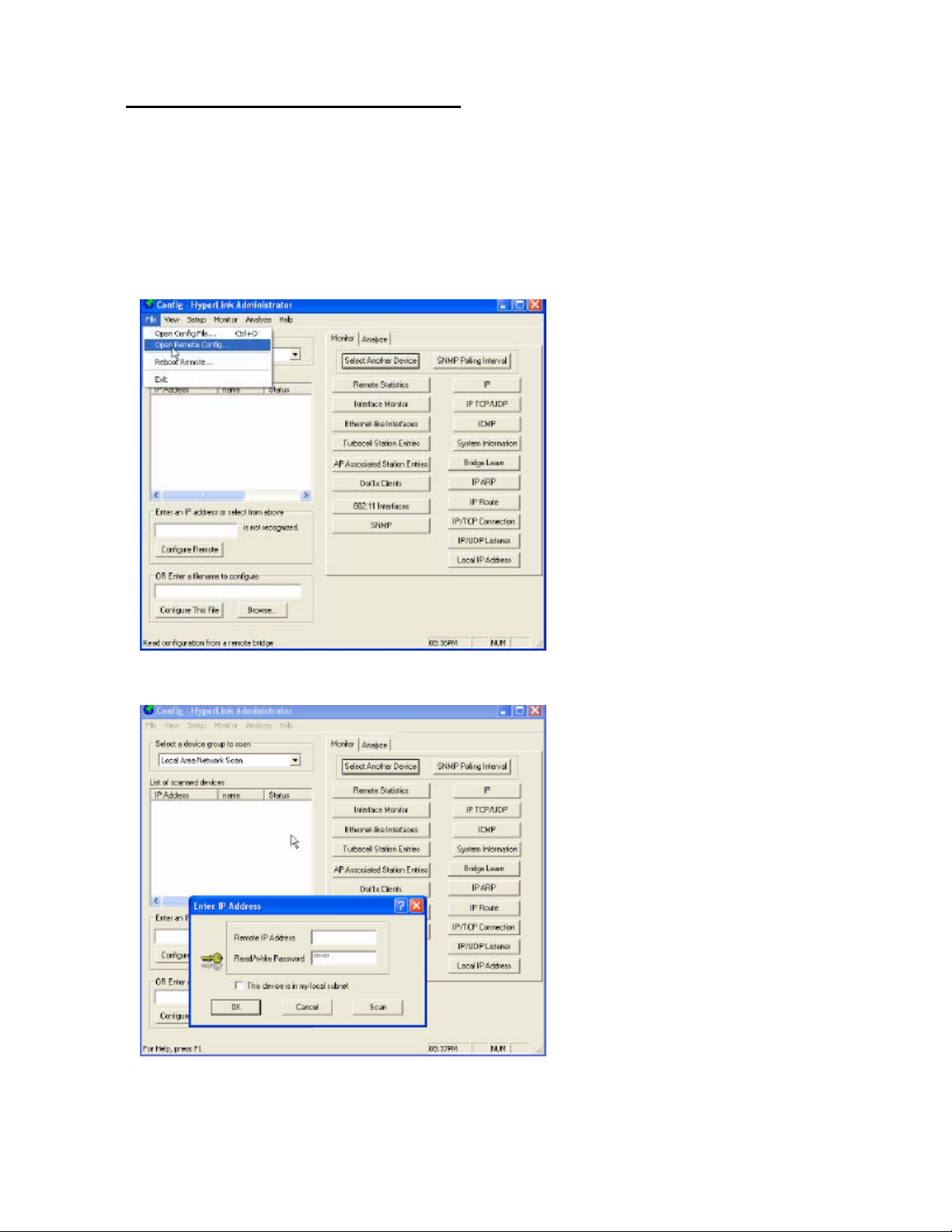
Launch the Network Configurator Utility
Click on File, Open Remote Config
Click on Scan to locate the Device
Select the Router to configure by Clicking on Name and Click on Change IP Button to
change to IP on your local subnet (similar to the configuration PC).

Setting the Password
The default password is “public”. Once you have accessed the security settings
change the password. Click OK to accept changes.
Select – This device is in my local subnet Click OK.
Once the screen pops up that Configuration has been Read- Click OK

Configure Router Parameters
Click on Setup – General Setup or Click Setup Tab on the right of Window and
General Setup
For Basic Bridging, the default parameters should be OK:
Enable Bridging, Enable Watchdog Reboot Timer (unit will reboot if there is not activity
for long period of time) and MAC Authentication (security)
Click on OK to accept these parameters.

Interface Setup
Click on Setup – Interface Setup or the Tab on the right – Interface Setup. The
Ethernet port by default is select as Remote and Enable. Click on Setup 2 (802.11b
radio interface)
Select the function of unit – One must be Base Station (does the polling) and
second unit must be Satellite Station (responds to polling).
In a multipoint application, there is one Base Station and all the remotes must be
configured as Satellite Stations.

Click on Advanced, Select a network ID and the maximum modulation rate you want
the radio to operate (higher speeds of 11 Mbps require better signal quality.) Click on
OK to accept changes
Configure the Operating Frequency
Click on Frequency, Select a Channel. Select an authorized frequency channel based
upon the specific antenna used from the table in Appendix B. Click on OK to accept
changes

Security Settings
You could Click next on Security and select encryption at this time (Not required for
basic configuration, implies 15-20% lower performance).
Click on OK to accept changes and return to Main Menu.
13. Click on Setup – System Access setup (or the Tab), select same Pass Phrase
for all the units on your system. Click OK to accept changes.
With this configuration, you should be able to communicate between the 2 units. You
could select TurboCell Access List to improve security (MAC address of unit allowed
to communicate and Bandwidth Control)

Saving the Configuration Settings
Please save your configuration changes, File , Save Config
Accept Yes to Save to the Unit with the IP you have assigned, it would take few
seconds and Unit will Reboot.

Appendix A - Minimum Separation Distance (cm)
29.9 29 28 27 26 24 21.8 17.5
9.9 8.9 8.0 7.1 6.3 5.0 3.9 2.7
11.1 10.0 8.9 8.0 7.1 5.6 4.4 3.0
12.5 11.2 10.0 8.9 8.0 6.3 4.9 3.0
12.5 11.2 10.0 8.9 8.0 6.3 4.9 3.0
12.5 11.2 10.0 8.9 8.0 6.3 4.9 3.8
15.7 14.1 12.6 11.2 10.0 8.0 6.2 3.8
15.7 14.1 12.6 11.2 10.0 8.0 6.2 3.8
N/A 17.8 15.9 14.1 12.6 10.0 7.8 -
15.7 14.1 12.6 11.2 10.0 8.0 6.2 -
17.6 15.9 14.1 12.6 11.2 8.9 6.9 -
Amplifier Power Rating (dB) Card Alone
RE05E 5
RE05U 5
HG2401U 1
HG2402RD 2
Antenna Model Gain (dBi)
HG2403UR 3
HG2404CU 3
HG2403RD 3
HG2405 5
HG2406U 6
HG2407U 7
N/A 20.0 17.8 15.9 14.1 11.2 8.7 -
N/A 21.2 18.9 16.8 15.0 11.9 9.2 -
N/A 21.2 18.9 16.8 15.0 11.9 9.2 -
N/A N/A 22.4 20.0 17.8 14.1 11.0 -
N/A N/A N/A 25.1 22.4 17.8 13.8 -
N/A N/A N/A N/A 31.7 25.1 19.5 -
HG2408U 8
HG2409U 8.5
HG2410U 10
HG2412U 12
HGV-2409U 8.5
HG2415U-PRO 15
Configurations with N/A are not permissible, via. FCC 15.247(b)(4)(i)
Configurations in RED can only be used in FIXED MOUNTED Installations
Configurations in BLACK Can be used in either MOBILE OR FIXED MOUNTED Installations
Appendix A

Card Alone
A
A
AN/AN/AN/A
Amplifier Power Rating
666 -
1000 800 630 500 400 250 150 (mW) - as labeled
FCC / IC Compliant Configurations - Channels of Operation
2447
2452
2457
2412
2417
2427
2422
2432
2437
2442
2462
Frequency (MHz)
ntenna Type Gain (dBi) 29.9 29 28 27 26 24 21.8 17.5 (dBm)
Appendix B
HG2401U whip/monopole 1 66666661-11
HG2402RD whip/monopole 2 66666661-11
HG2403RD whip/monopole 3 66666661-11
ntenna Model
HG2403UR whip/monopole 3 66666661-11
HG2404CU whip/monopole 3 66666661-11
RE05E whip/monopole 5 66666661-11
RE05U whip/monopole 5 66666661-11
123456789
HG2405 whip/monopole 5 6666666 -
HG2407U whip/monopole 7 N/A 666666 -
HG2408U whip/monopole 8 N/A 666666 -
HG2409U whip/monopole 8.5 N/A 6 66666 -
HG2410U whip/monopole 10 N/A N/A 6 6666 -
HG2406U whip/monopole 6 6666666 -
HG2412U whip/monopole 12 N/A N/A N/A 6666 -
HGV-2409U whip/monopole 8.5 N/A 6 66666 -
HG2415U-PRO whip/monopole 15 N/
Configurations in BLUE can be used in either MOBILE OR FIXED MOUNTED Installations (NO FILTER REQUIRED)
Configurations in BLACK can be used in either MOBILE OR FIXED MOUNTED Installations (FILTER REQUIRED)
Configurations with "-" are NOT PERMISSIBLE as they do not meet the FCC Part 15 restricted band limits
Configurations in RED can only be used in FIXED MOUNTED Installations (FILTER REQUIRED)
Configurations with N/A are NOT PERMISSIBLE, via. FCC 15.247(b)(4)(i)
Channel
10
11

Important Information
Your wireless system has been installed and configured by an RF professional to comply
with FCC Part 15 regulations. These limits are designed to provide reasonable
protection against harmful interference when the equipment is operated in a commercial
environment. This equipment generates, uses and can radiate radio frequency energy
and, if not installed and used in accordance with the installation and configuration
manual, may cause harmful interference to radio communications. Operation of this
equipment in a residential area is likely to cause harmful interference in which case the
end user will be required to correct the interference at their own expense.
Modifications to this system including changing the antenna, power setting or transmit
channel may result in a non-compliant system, and should only be undertaken by
professional installers after reading the Installation Guide for this system.
For further information contact:
Hyperlink Technologies
Technical Support Dept.
1201 Clint Moore Road
Boca Raton, FL 33487
Email: support@hyperlinktech.com
SAFETY NOTICE
This equipment complies with FCC radiation exposure
limits set forth for an uncontrolled environment when
installed as directed. When this device is installed as
a fixed-mount application there is a minimum required
separation distance of one (1) meter between the
antenna and all persons during normal operation. For
mobile mounted antennas, the required separation
distance is a minimum of twenty (20) cm between the
antenna and all persons during normal use.
Installer: Please post this notice in a prominent location near the transmitter.
 Loading...