

L-com.com
10/100/1000TX Gigabit Ethernet
Media Converter with One Duplex SC/ST Fiber Port
LC-MCGxx-XX Series
User’s Manual
FCC Warning
The LC-MCGxx-XX series of media converters have been tested and found to comply within the limits of a Class B digital device, pursuant to
Part 15 of the FCC Rules. These standards are designed to provide reasonable protection against harmful interference when these devices are
operated in a commercial environment. These devices generate, use and can radiate radio frequency energy and may cause harmful interference
to radio communications unless installed in accordance with this User’s Manual. Operation of these devices in a residential area is likely to cause
harmful interference which will make the user responsible for the appropriate remedial action at his/her own expense.
CE Warning
These are Class A products. In a domestic environment these products may cause radio interference. The user will need to take appropriate
precautions.
Notices
• This product is suitable for indoor use only
• Put the dust covers back on the fiber ports when not in use
• WARNING: Never look directly down into any fiber optic port as retinal damage may result
Installation (Stand Alone Use)
1. Place the Converter on a clean, flat and safe location that has easy & close access to AC power.
2. Connect a Cat5e (or better) Ethernet cable to the RJ45 port of the LC-MCGxx-XX series converter. (This port is auto-negotiating and
auto-crossover)
3. Connect the other end of the Cat5e (or better) Ethernet Cable into your network device (Switch, Router, PC, etc.)
4. Remove the dust cover plugs from the duplex fiber port.
5. Identify the TX and RX legs of your duplex fiber optic cable and the match them up with the duplex fiber port. Insert the appropriate legs into
the duplex fiber port.
6. Insert the other end of the fiber optic cable into your remote network device or 2nd media converter making sure to keep track of which ones
are the TX & RX legs.
7. Insert the power cable plug directly into its receptacle located at the back of the LC-MCGxx-XX series converter.
8. Plug the power adapter into an available AC socket.
9. Check the LED’s as the device is powered on to verify that the Power LED is lit. If not, check that the power cable is inserted correctly into the
unit and securely plugged into the wall outlet.
10. Check the Network connection LED’s to make sure you are connected and able to transmit data.
Installation (Use with L-com LC-MCC14AA 14 Slot Media Converter Chassis)
1. Check the orientation of the media converter, and then install the retention bracket that is included with the chassis. (For detailed installation
instructions for the Chassis refer to its user’s manual)
2. Slide the Converter into the specific slot in the chassis that you intend to use making sure to seat the unit properly onto the Power connection
at the back of the slot then secure to chassis with bracket installed in step 1.
3. Connect a Cat5e (or Better) Ethernet cable to the RJ45 port of the LC-MCGxx-XX series converter. (This port is auto-negotiating and autocrossover)
4. Connect the other end of the Cat5e (or better) Ethernet Cable into your network device (Switch, Router, PC, etc.)
5. Remove the dust cover plugs from the duplex fiber port.
7. Identify the TX and RX legs of your duplex fiber optic cable and then match them up with the SFP transceiver module. Insert the appropriate
legs into the SFP Module.
8. Insert the other end of the fiber optic cable into your remote network device or 2nd media converter making sure to keep track of which ones
are the TX & RX legs.
9. Check the LED’s to verify that the Power LED is lit. If not, check that the converter is properly seated onto the DC power connection in the
chassis and that the chassis power supplies are plugged in and turned on.
10. Check the Network connection LED’s to make sure you are connected and able to transmit data.
L-com Global Connectivity | 50 High St., West Mill, 3rd floor, Suite #30 | North Andover, MA 01845 | USA
© L-com, Inc. All Rights Reserved. L-com Global Connectivity and the L-com Logo are registered marks.
Toll Free Ordering and Technical Support: 1-800-343-1455 Visit our website at www.L-com.com
L-com.com
Packing List
The box should contain the following items:
• (1) LC-MCxx-XX 10/100/1000TX to Duplex SC or ST (See Order Chart below for details)
• (1) AC-DC Power Adapter (Output: 5VDC, 2 Amps max.) For standalone use
• This User’s Manual
Please notify us immediately if any items are missing or damaged.
Overview
The LC-MCGxx-XX series of media converters are designed to meet the various needs for extending network segments and is able to extend a
copper based network via fiber cable to a maximum distance up to 20km. (Depending on which unit you purchase)
Our LC-MCGxx-XX series of media converters are fully compliant with IEEE802.3, IEEE802.3U, IEEE802.3ab, 10/100/1000Base-Tx, and
IEEE802.3z 1000Base-SX/LX, standards. They can be used as standalone converters or installed into one of our LC-MCC14AA 14 slot Media
Converter chassis. Operation status can be locally monitored through a set of diagnostic LEDs located on the front panel.
(See LED indicators Chart for Details)
Features
• 10/100/1000Base-Tx to 1000Base-SX/LX Converter
• Complies to IEEE802.3, IEEE802.3U, IEEE802.3ab & IEEE802.3z
• One 10/100/1000 Mbps RJ45 Ethernet port (maximum segment length 100 meters)
• One Duplex ST or SC port (depending on unit purchased, see order chart below
for details)
• Auto MDI/MDI-X support on RJ45 port
• Flow control: IEEE802.3x flow control for duplex mode, backpressure flow control
for half duplex mode.
• Status LEDs for easy monitoring of device’s status
• Extends distance up to 2km (6,561ft or 1.2 miles) when using either of our
LC-MCGMM-XX multimode fiber units or up to 20km (65,616ft or 12.4 miles) when
using either of our LC-MCGSM-XX single mode fiber units.
(See Order Chart below for details)
Ordering Chart LED Indicators
LC-MCGMM-ST 10/100/1000TX RJ45 to 1000SX Multimode Duplex
ST (2Km)
LC-MCGMM-SC 10/100/1000TX RJ45 to 1000SX Multimode Duplex
SC (2Km)
LC-MCGSM-ST 10/100/1000TX RJ45 to 1000LX Single mode Duplex
ST (20Km)
LC-MCGSM-SC 10/100/1000TX RJ45 to 1000LX Single mode Duplex
SC (2Km)
LED FUNCTION STATUS DESCRIPTION
PWR Power LED ON Power is ON
TP/ACT UTP interface
link/action status
Specifications
ITEM SPECIFICATION
Ethernet
Standards
Ethernet Port Cat-5e (or better) (10/100/1000Mbps) unshielded twisted
Fiber Port Duplex ST or Duplex SC
LEDs PWR, TP/ACT, 100M, 1000M, FX/ACT, FDX
Powe r External 5VDC 2A
Dimensions 3.7L x 2.79W x 1H (95mm x 71mm x 26mm)
Safety UL certified
Temperature Operating: 32°~113°F (0°~45°C)
Humidity Operating: 10~90% (non-condensing)
EMC FCC Part 15 (Class B)
IEEE802.3: 10Base-T
IEEE802.3u: 100Base-TX
IEEE802.3ab: 1000Base-T
IEEE802.3z: 1000Base-SX/LX
(Depending on Unit purchased)
IEEE802.3x: Flow control and back pressure
pair cable (100m Max)
Storage: 14°~158°F (-10°~70°C)
Storage: 10~90% (non-condensing)
CE EMC (Class A)
100M Copper
interface speed
1000M Copper
interface speed
FX/ACT Fiber interface
link/action status
FDX Copper interface
duplex mode
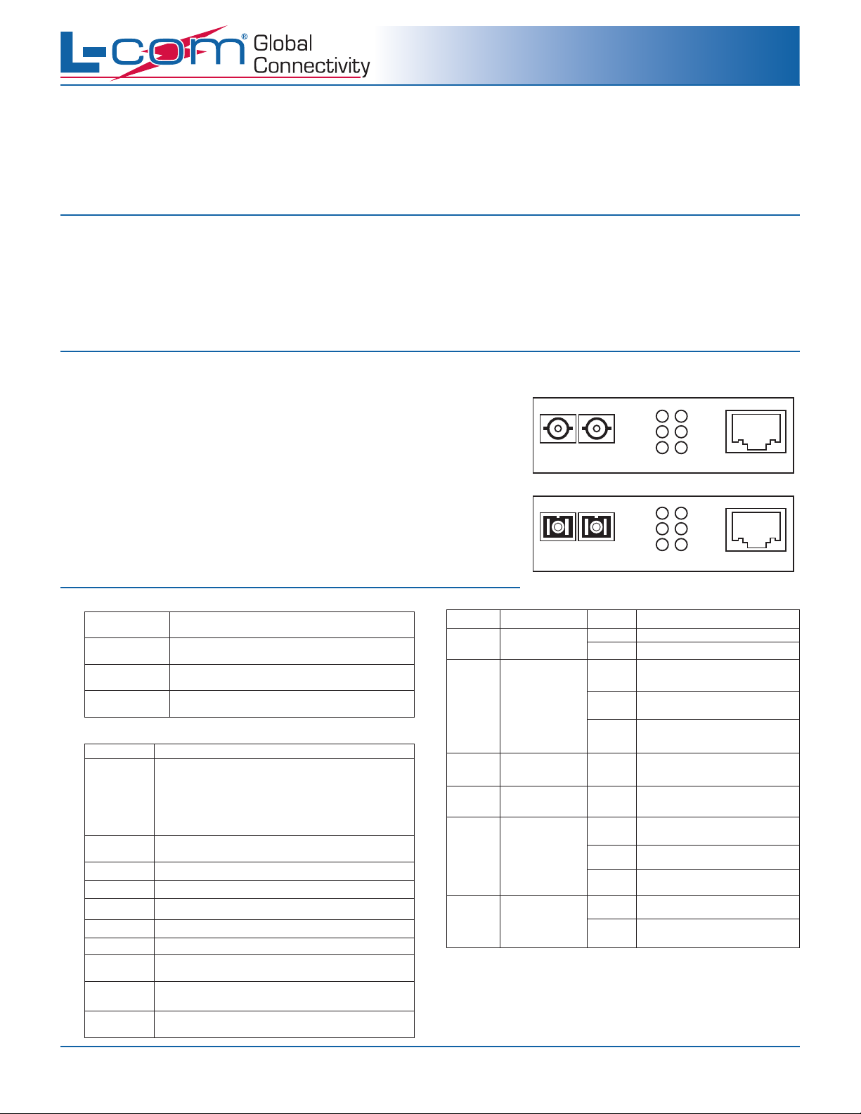
TX RX
1000M
FX/ACT
Duplex ST port version
TX RX
1000M
FX/ACT
Duplex SC port version
OFF Power OFF
ON
Blink
OFF
ON
ON
ON
Blink
OFF
ON Full duplex
OFF Half duplex
100M
TP/ACT
FDX
FDX
10M Copper Cable Link or Better
connected
Copper port is
transmitting data
No Cable connected or No
Network Connection
Copper port Network Connection
speed at 100M
Copper port Network
Connection speed is at 1000M
Fiber Optic Network connection is
present
Fiber Optic port is
transmitting data
Fiber is disconnected or no
Network Connection
PWR
100M
TP/ACT
PWR
RJ45
RJ45
L-com Global Connectivity | 50 High St., West Mill, 3rd floor, Suite #30 | North Andover, MA 01845 | USA
© L-com, Inc. All Rights Reserved. L-com Global Connectivity and the L-com Logo are registered marks.
Toll Free Ordering and Technical Support: 1-800-343-1455 Visit our website at www.L-com.com
 Loading...