

Page 1
Quick Start Guide LC-IND232-422-485
Optically Isolated RS-232 to RS-422/485 Converter
Introduction
The LC-IND232-422-485 is an optically isolated RS-232 to RS-422/485 converter. RS-232 signals interface through a DB9 female connector or a terminal block. RS-422/485 signals
and power inputs connect to the terminal block. Terminal block s are arranged to allow easy wiring inside a control panel.
Built-in Automatic Send Data Control circuitry allows quick set-up and eliminates the need for external software drivers to control handshake signals. The converter operates on
externally sourced 10-30 VDC power.
Features
• Extend data up to 1.2 km (4,000 ft.)
• 2 kV optical isolation on input/output
• Wide operating temperature (-40 to +80 °C)
• Modbus compatible
• NEMA TS2
• Automatic Send Data Control
Installation
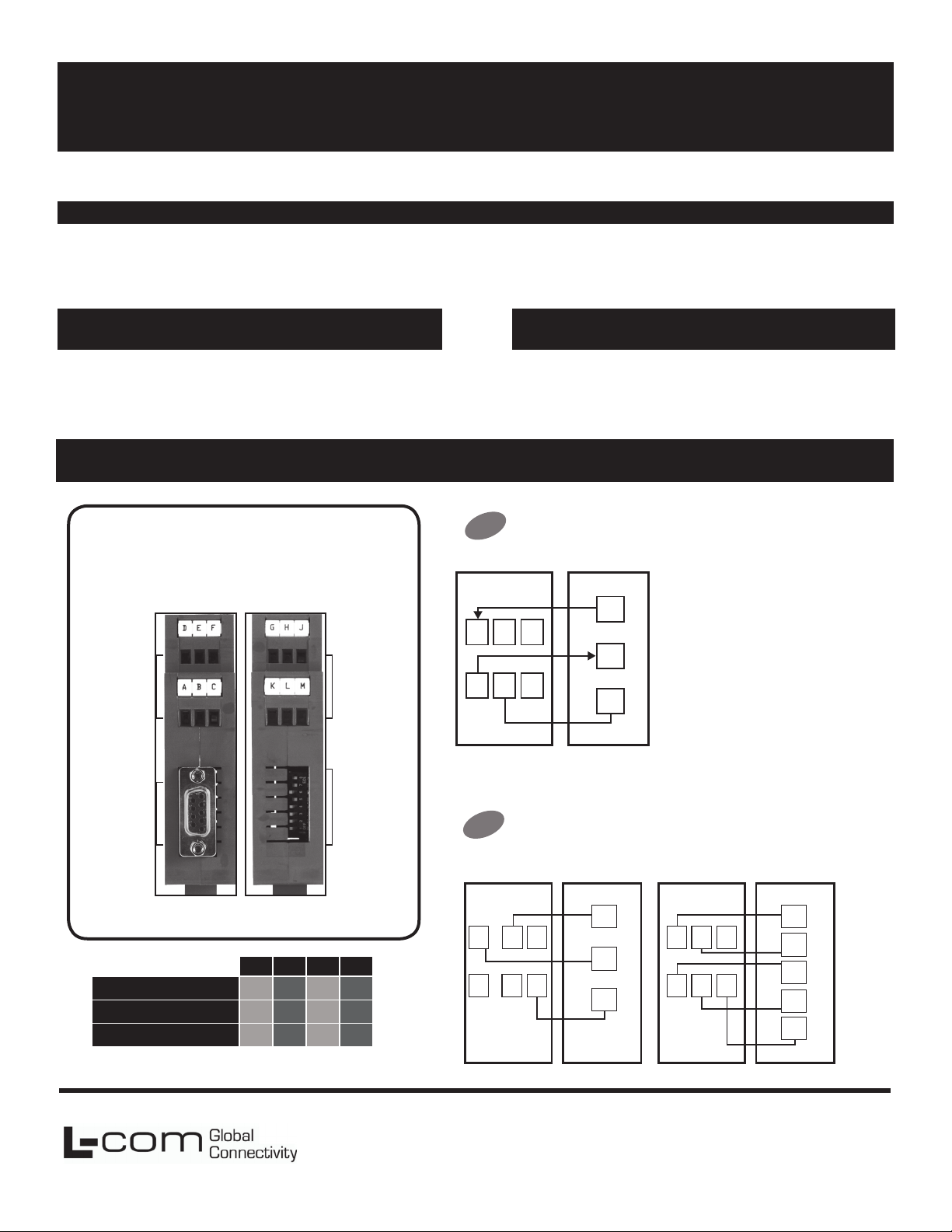
Product Overview
Top View
(232 and Power Side)
Terminal Block
Connectors
A – F
• Power 10-30 VDC, .5 W
• LED indicates power and data ow
Bottom View
(422/485 Side)
Terminal Block
Connectors
G – M
Package Contents
• LC-IND232-422-485 Serial Converter
• Additional items required but not included:
Power Supply
RS -232 Cable
RS-422/485 Cable
Connect Your RS-232 Device
1
(Terminal Block OR DB9 Port)
You r D ev ic eLC-IND232-42 2-4 85
TD
D
RD
AEBFC
GND
DTE
Computer
• Use a straight through DB9 to
DB9 if you are connecting to a
computer (DTE).
• Use a cross over (null modem)
DB9 to DB9 if you are not
connecting to a computer.
(DCE)
DB9 F PINS
Please Note:
Terminal block and DIP switch settings located on product.
SW-1 SW-2 SW-3 SW-4
RS-485 2-Wire Half Duplex
RS-485 4-Wire Full Duplex
RS-422 Full Duplex
ON ON ON ON
ON OFF OFF OFF
OFF OFF OFF OFF
DIP Switches
Note: Termination is not usually required.
L-com Global Connectivity
50 High Street
West Mill 3rd oor, Suite #30
North Andover, MA 01845 USA
1 – 8
Set The 422/485 Side of the Converter
2
2 Wire 485 4 Wire 485/422
LC-IND2 32-42 2-48 5
G
HLJ
K
M
Your De vi ce
DATA
B (+)
DATA
A (-)
GND
LC-IND2 32-42 2-48 5
G
KHLJM
Your De vi ce
RDA (-)
RDB (+)
TDA (-)
TDB (+)
GND
Toll Free: 800-341-5266
PH: 978-682-6936
Fax: 978-689-9484
Page 2
Set the Dipswitch Settings for Data Rate
3
SW-6 SW-7 SW-8 Timeout (MS)
Safety Information
When installed in the end-use equipment,
consideration should be given to the following:
2400
4800
9600
19.2K
Termination Switch: Set to OFF
4
OFF OFF ON 4.16
OFF ON OFF 2.08
ON OFF OFF 1.04
ON ON ON 0.580
(Recommended)
SW-5
Use the 120Ω
Built-in Termination
Use External or
No Termination
5
Connect Your Power Supply
10-30 VDC power required.
Terminal G = negative. Terminal F = positive.
ON
OFF
This device is to be mounted in a suitable enclosure
in the end product.
• Input Voltage: 10 – 30 VDC
• Input Power: 0.5 Watts
• Wire Range: 12 – 24 AWG
• Tightening Torque: 4 kgf-cm
• Use copper wire only
• Maximum surrounding ambient air temperature
80 C.
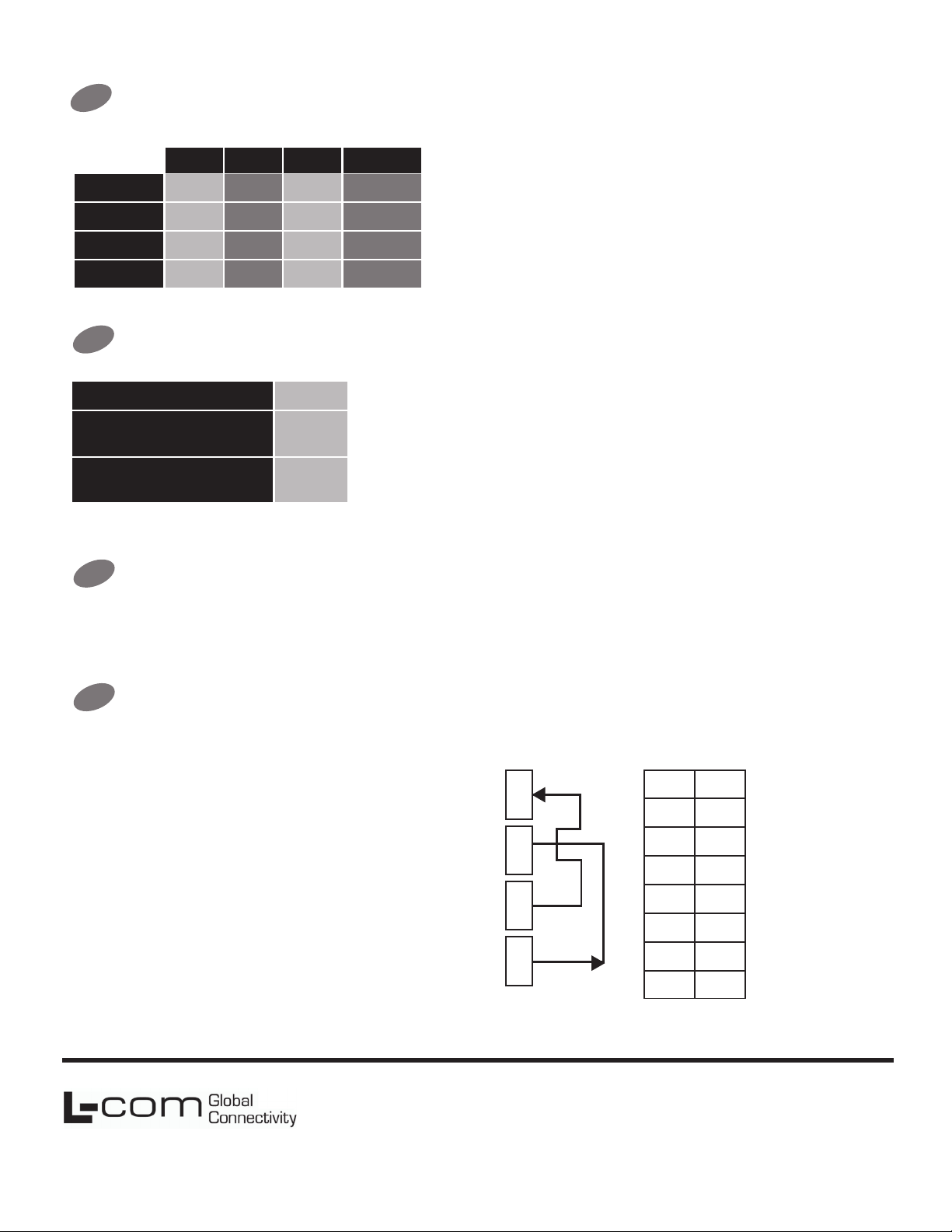
Loopback Test (Optional)
6
To verify serial port and LC-IND232-422-485 functionality
• Configure for RS-485 four wire, 9600 baud.
• Jumper terminals H to L and G to K.
• Connect a PC to the RS-232 port see Step 1).
• Using HyperTerminal or similar program, connect to the
appropriate COM port
(remember to set the baud rate at 9600).
Turn off HyperTerminal local echo.
• Start typing. If you can see the data you are typing, you
have a good loop-back. If you cannot, contact tech
support.
• LED Indicators: Power is ON when power is applied. TD
flashes when RS-422/485
data is sent. RD flashes when
L-com Global Connectivity
50 High Street
West Mill 3rd oor, Suite #30
North Andover, MA 01845 USA
L
K
H
G
Set DIP
Switches to:
1
OFF
2
OFF
3
OFF
4
5
OFF
6
OFF
7
OFF
8
ON
ON
RS-485 4-Wire
Toll Free: 800-341-5266
PH: 978-682-6936
Fax: 978-689-9484
710-10664-00_LC-IND232-422-485
 Loading...