

Page 1
Quick Start Guide LC-232SW-422-485
Universal Converter RS-232, 4-wire RS-422, 2-wire or 4-wire RS-485
Introduction
The LC-232SW-422-485 provides RS-232 to RS-422/R S-485 conversion using either por t-power or an ex ternal power supply. Data is conver ted in both directions, RS-232 Transmit data is
converted to balanced RS- 422 or RS-485 Transmit, and Received RS-422/RS-485 signals are converted to RS-232. Unlike converters which require programming hardware handshaking
signals to control RS-485 or R S-422 operation, the LC-232SW-422-485 provides automatic control. In RS- 422 mode, the transmit ter and receiver are always enabled. The operating mode is
set with 4 switches. The LC-232SW-422-485 is powered by the RS-232 signal lines whether they are set high or low. If not enough power is available from the por t, or no handshaking lines
are available, a DC jack is provided to connect a 12VDC supply. The DB9 female connector for RS-232 is wired as DCE (like a modem).
Features
• Selec table R S-485 2-wire half-duple x, or RS- 485 4-wire full-duplex operation
• Selec table R S-422 ope ration
• DB9 Female RS-232 Conne ction
• Terminal Blocks for RS -422/RS-485
• Port power or External 12V DC p ower (jack)
• Automatic RS-485 Driver Control
Installation
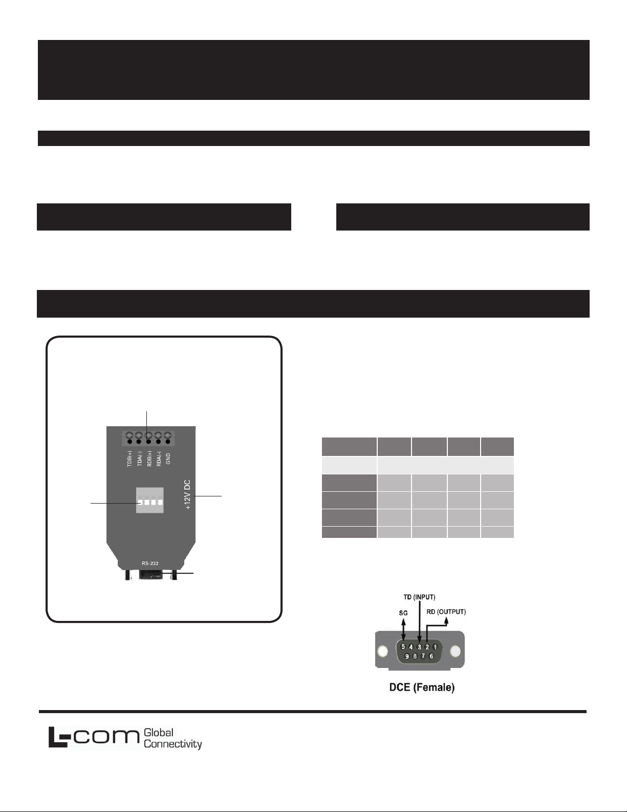
Product Overview
Terminal Block
Connectors
DIP
Switches
Power
Port
2.5 mm
Package Contents
• LC-232SW-422- 485
• Additional items required but not included:
Power Supply
RS-422/485 Cable
Power
External power is not required if two RS-232 output handshake
lines (RTS & DTR) are available and the cable run is short. Less
than 3mA is required to operate the LC-232SW-422-485. A
+12VDC power supply with a 2.5mm plug (tip positive) can
also be used to power the device.
Operating Mode Switch Settings
Switches
Operating
Mode
RS-485 2-Wire
(half duplex)
RS-485 4-Wire
(full duplex)
RS-422 4-Wire
(full duplex)
Loopback Test
Switch 1
(Tx)
As Desired Echo On 2-Wire 2-Wire
Switch 2
(Rx)
RS-485 Echo Off 2-Wire 2-Wire
RS-485 Echo On 4-Wire 4-Wire
RS-422 Echo On 4-Wire 4-Wire
Switch 3
(bridge)
Switch 4
(bridge)
Pins 1, 4 and 6 are jumpered internally.
RS-232
Pins 7 and 8 are jumpered internally
Connection
L-com Global Connectivity
50 High Street
West Mill 3rd oor, Suite #30
North Andover, MA 01845 USA
Toll Free: 800-341-5266
PH: 978-682-6936
Fax: 978-689-9484
Page 2
RS-232 Operation
RS-232 connections require pins 2 (RD), 3 (TD), and 5 (Signal
Ground). Pins 7 (RTS) and 8 (CTS) are tied together, and pins 6 (DSR),
1 (DCD), and 4 (DTR) are also tied together. Any incoming data
lines in either the high or low state are used to port power the LC232SW-422-485. The more handshake lines available, the more likely
the unit can be port powered.
RS-422/485 Operations
The RS-422 standard was designed to extend RS-232 connections, the
RS-485 standard is an enhanced version which allows multiple drivers/
receivers to alternately share one pair of wires for transmit and receive,
or two pairs for full duplex operation. With a RS-485 device, the transmitter/driver is only active while transmitting, but when not transmitting, is set to a high impedance state which allows another transmitter
to send data on the same wire pair. In the LC-232SW-422-485, the
driver is controlled by circuitry which senses the RS-232 TD input and
automatically enables transmit. In half duplex operation, the receiver is
enabled when not transmitting (Echo Off).
The LC-232SW-422-485 does not require any handshaking lines to
control the driver in RS-422 or RS-485 mode. When Switch 1 set to
RS-422, the driver is always enabled. When switch 1 is in the RS-485
position, the RS-485 driver is automatically enabled during each Space
state by the RS-232 data. During the Mark or idle state, the RS-485
driver is disabled and the data lines are held in the Mark state by Bias
provided by the 4.7K Ohm pull-up and pull-down resistors. The value
of these resistors may need to be changed to a different value when
termination is used in order to maintain the proper DC bias during the
idle state.
RS-485 2-Wire Half Duplex
This communications mode is used to connect several RS-485 devices
to the same network with a minimum number of wires when only one
unit talks at a time. All units are normally in Receive mode, listening for
data. When data is requested, the addressed device waits (1 delay
time) then transmits, afterwards, goes back to receive. To use this mode
set Switch 1: RS-485 , Switch 2: Echo Off, and Switches 3 and 4 to
2-Wire.
RS-485 4-Wire Full Duplex
This mode is used for 4-Wire Master/Slave. Devices can be polled and
respond faster, unlike half duplex mode, no turn-around time delay is
needed between requests and responses. The RS-485 driver works the
same as in haft duplex but the receiver is always enabled. This can
allow devices to receive information even while they are responding to
a request. To use RS-485 4-Wire mode, set Switch 1: RS-485, Switch
2: Echo On, and Switches 3 and 4 to 4-Wire. When the 4WSD9TB
is used as a Master in a single master system, Switch 1 can be set RS422 since it is the only transmitter. When used for a Slave device, the
RS-232 device must provide addressability, and RS-485 mode should
be selected. As in 2-Wire operation RS-485 Biasing is provided on
Receive, and should be provided on the transmit pair by the End-of-Line
slave device, RS-422 Transmit mode requires no bias on transmit.
RS-422 4-Wire Full-Duplex or 2-Wire Simplex
This communications mode is typically used for point-to-point communications over long distances with better noise immunity than RS-232.
Another common use is as a single master in a master/slave configuration, where the slave devices only receive, but don’t transmit back.
In RS-422 the transmitter and receiver are always enabled to allow
full-duplex communications. Connections require one twisted pair for
Transmit, another twisted pair for Receive and a ground reference wirei
for a total of 5 lines to operate properly. To set this mode, Table 1:
Switch 1: RS-422, Switch 2: Echo On, and Switches 3 and 4: 4-wire
Troubleshooting Operation
If an RS-485 or RS-422 device doesn’t respond to data requests, try
swapping the polarity of the data lines. Some devices are marked
opposite the RS-485 or RS-422 Standard. 4-Wire devices must swap
polarity of each pair. Operation of the converter can be checked with
HyperTerminal. Set Converter to Loopback Test mode. Open HyperTerminal using the Com port connected to, set baud rate, set Flow Control
to None, type characters. Each character should show as typed, two
if local echo is on.
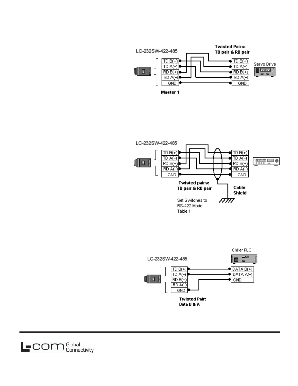
4-Wire RS-485
4-Wire RS-422
2-Wire RS-485
L-com Global Connectivity
50 High Street
West Mill 3rd oor, Suite #30
North Andover, MA 01845 USA
Toll Free: 800-341-5266
PH: 978-682-6936
Fax: 978-689-9484
710-10683-00_LC-232SW-422-485
 Loading...