

OUTDOOR INSTALLATION WARNING
IMPORTANT SAFETY PRECAUTIONS:
LIVES MAY BE AT RISK! Carefully observe these instructions and any special instructions that are included with the equipment
you are installing.
IMPORTANT: Look over the site before beginning any installation, and anticipate possible hazards, especially these:
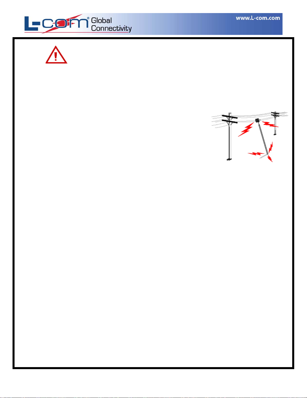
CONTACTING POWER LINES CAN BE LETHAL. Make sure no power lines are
anywhere where possible contact can be made. Antennas, masts, towers, guy wires or cables
may lean or fall and contact these lines. People may be injured or killed if they are touching or
holding any part of equipment when it contacts electric lines. Make sure there is NO possibility
that equipment or personnel can come in contact directly or indirectly with power lines.
Assume all overhead lines are power lines.
The horizontal distance from a tower, mast or antenna to the nearest power line should be at least twice the total length of the
mast/antenna combination. This will ensure that the mast will not contact power if it falls either during installation or later.
TO AVOID FALLING, USE SAFE PROCEDURES WHEN WORKING AT HEIGHTS ABOVE GROUND.
• Select equipment locations that will allow safe, simple equipment installation.
• Don’t work alone. A friend or co-worker can save your life if an accident happens.
• Use approved non-conducting ladders and other safety equipment. Make sure all equipment is in good repair.
• If a tower or mast begins falling, don’t attempt to catch it. Stand back and let it fall.
• If anything such as a wire or mast does come in contact with a power line,
MOVE IT
• Don’t attempt to erect antennas or towers on windy days.
. Instead, save your life by calling the power company.
DON’T TOUCH IT OR ATTEMPT TO
MAKE SURE ALL TOWERS AND MASTS ARE SECURELY GROUNDED, AND ELECTRICAL CABLES
CONNECTED TO ANTENNAS HAVE LIGHTNING ARRESTORS.
in case of lightning, static build-up, or short circuit within equipment connected to the antenna.
• The base of the antenna mast or tower must be connected directly to the building protective ground or to one or more
approved grounding rods, using 1 OAWG ground wire and corrosion-resistant connectors.
• Refer to the National Electrical Code for grounding details.
• Lightning arrestors for antenna feed coaxial cables are available from HyperLink Technologies, Inc.
This will help prevent fire damage or human injury
IF A PERSON COMES IN CONTACT WITH ELECTRICAL POWER, AND CANNOT MOVE:
• DON’T TOUCH THAT PERSON, OR YOU MAY BE ELECTROCUTED.
• Use a non-conductive dry board, stick or rope to push or drag them so they no longer are in contact with electrical power.
• Once they are no longer contacting electrical power, administer CPR if you are certified, and make sure that emergency
medical aid has been requested.
Copyright © This drawing is property of L-com Global Connectivity. All rights reserved.
WWW.L-COM.COM E-MAIL: SALES@L-COM.COM PHONE: 1-800-343-1455 FAX: 1-978-689-9484
© L-com, Inc. All Rights Reserved. L-com Global Connectivity and the L-com logo are registered marks.
L-COM, INC. 45 BEECHWOOD DRIVE NORTH ANDOVER, MA 01845
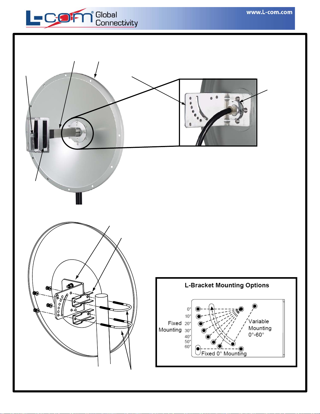
Installation Instructions
Self-Tapping
Screw
Feed Reflector
(shown vertical)
(Shown for Vertical Polarization)
Feed Horn
Dish
L-Bracket
L-Bracket
Clamp
Model: HG2418D
1. Attach the L-Bracket to the rear of the dish using
the 4-sets of screws included (see below).
Retaining
Nut
Rear View
2. Attach the Feed Reflector to the Feed Horn and
secure with Self-tapping screw included. Then
insert Feed Horn assembly into the front of the
dish and secure with Retaining Nut (see above).
Installation Note: The Feed Horn can be oriented
for either vertical or horizontal polarization (vertical
polarization shown in photo). For horizontal polarization
rotate Feed Horn Assembly so that the Feed Reflector
is orientated horizontally, then insert assembly into dish.
3. Secure antenna assembly to mast using U-Bolts,
Clamp and hardware. (Note: Only one U-Bolt is
required when using tilt feature of L-Bracket)
Mast
IP-00089 Rev. A – 01/07 Page 2/2
WWW.L-COM.COM E-MAIL: SALES@L-COM.COM PHONE: 1-800-343-1455 FAX: 1-978-689-9484
© L-com, Inc. All Rights Reserved. L-com Global Connectivity and the L-com logo are registered marks.
Antenna can be mounted in a tilt position. See
Below for mounting options.
U-Bolt
L-COM, INC. 45 BEECHWOOD DRIVE NORTH ANDOVER, MA 01845
L-Bracket shown for down-tilt mounting. For up-tilt,
rotate bracket 180 degrees when attaching to antenna.
Copyright © This drawing is property of L-com Global Connectivity. All rights reserved.
 Loading...