

L-com HG2412Y User Manual
www.L-com.com
IMPORTANT SAFETY PRECAUTIONS:
LIVES MAY BE AT RISK! Carefully observe these instructions and any special instructions that are included with the equipment you are installing.
IMPORTANT:
Look over the site before beginning any installation, and anticipate possible hazards, especially these:
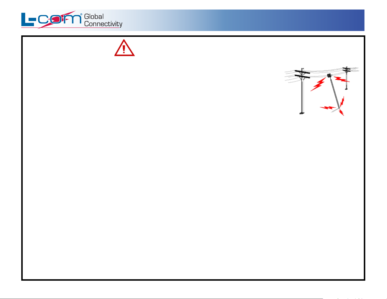
CONTACTING POWER LINES CAN BE LETHAL. Make sure no power lines are anywhere where possible
contact can be made. Antennas, masts, towers, guy wires or cables may lean or fall and contact these lines.
People may be injured or killed if they are touching or holding any part of equipment when it contacts electric lines.
Make sure there is NO possibility that equipment or personnel can come in contact directly or indirectly with power lines.
Assume all overhead lines are power lines.
The horizontal distance from a tower, mast or antenna to the nearest power line should be at least twice the total length of the mast/antenna combination.
This will ensure that the mast will not contact power if it falls either during installation or later.
TO AVOID FALLING, USE SAFE PROCEDURES WHEN WORKING AT HEIGHTS ABOVE GROUND.
• Select equipment locations that will allow safe, simple equipment installation.
• Don’t work alone. A friend or co-worker can save your life if an accident happens.
• Use approved non-conducting ladders and other safety equipment. Make sure all equipment is in good repair.
• If a tower or mast begins falling, don’t attempt to catch it. Stand back and let it fall.
• If anything such as a wire or mast does come in contact with a power line,
DON’T TOUCH IT OR ATTEMPT TO MOVE IT. Instead, save your life
by calling the power company.
• Don’t attempt to erect antennas or towers on windy days.
MAKE SURE ALL TOWERS AND MASTS ARE SECURELY GROUNDED, AND ELECTRICAL CABLES CONNECTED TO ANTENNAS
HAVE LIGHTNING ARRESTORS.
equipment connected to the antenna.
This will help prevent fire damage or human injury in case of lightning, static build-up, or short circuit within
• The base of the antenna mast or tower must be connected directly to the building protective ground or to one or more approved grounding rods, using 1
OAWG ground wire and corrosion-resistant connectors.
• Refer to the National Electrical Code for grounding details.
• Lightning arrestors for antenna feed coaxial cables are available from HyperLink Technologies, Inc.
IF A PERSON COMES IN CONTACT WITH ELECTRICAL POWER, AND CANNOT MOVE:
• DON’T TOUCH THAT PERSON, OR YOU MAY BE ELECTROCUTED.
• Use a non-conductive dry board, stick or rope to push or drag them so they no longer are in contact with electrical power.
• Once they are no longer contacting electrical power, administer CPR if you are certified, and make sure that emergency medical aid has been requested.
IP-00010 Rev. B – 07/05 Page 2/2
L-COM, INC. 45 BEECHWOOD DRIVE NORTH ANDOVER, MA 01845
WWW.L-COM.COM E-MAIL: SALES@L-COM.COM PHONE: 1-800-343-1455 FAX: 1-978-689-9484
© L-com, Inc. All Rights Reserved. L-com Global Connectivity and the L-com logo are registered marks.
Copyright © This drawing is property of L-com Global Connectivity. All rights reserved.
www.L-com.com
INSTALLATION INSTRUCTIONS: HG2412Y, HG2312Y
Location
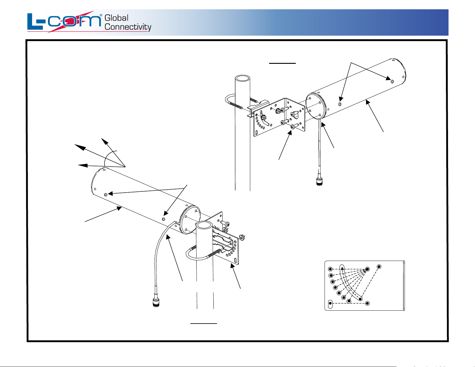
1. The antenna receives and transmits within a horizontal angle of 45°.
Locate the antenna so linked equipment will be in this beam. The
center of the antenna beam is the long axis of the antenna, with the
beam pointing away from the mast.
2. Surrounding objects such as metal structures, trees, power lines,
other antennas, etc. will reduce antenna efficiency and may block
signals. Choose a location that is high and clear of obstruction.
3. Make absolutely sure that the location is safe, especially from
possible contact with power lines. See warning on back.
45° Beam Direction
(2) Drain Hole Plugs
(2) Open Drain Holes
on bottom
Horizontal Polarized Mounting
1. To mount the antenna in the horizontal
polarized position, rotate antenna into
the position shown in Figure B. The
cable should be exiting from the side of
the antenna and the plugged drain
holes facing down.
2. Remove (2) drain hole plugs from
bottom and insert into side holes.
3. Attach antenna to L-Bracket using the
(4) pan head screws.
IP-00010 Rev. B – 07/05 Page 1/2
Side exiting cable
Figure B
Horizontal Polarized Position
L-Bracket
Figure A
(2) Drain Hole Plugs
Vertical Polarized Position
(As shipped from factory)
(2) Open Drain Holes
on bottom
Bottom exiting cable
(4) Pan Head Screws
Mounting
1. The antenna can be vertical polarized mounted (Figure A) or
horizontal polarized mounted (Figure B). It is shipped from the
factory in the vertical polarized position.
2. Mount the antenna as shown, ensuring U-Bolt nuts are securely
tightened to prevent antenna shift in high wind.
3. The antenna can be mounted in a up or down tilt position from 0-60°.
See below for mounting options.
L-Bracket Mounting Options
0°
10°
Fixed
Mounting
20°
30°
40°
50°
60°
Fixed 0° Mounting
L-Bracket shown for down-tilt mounting. For up-tilt,
rotate bracket 180 degrees when attaching to antenna.
Copyright © This drawing is property of L-com Global Connectivity. All rights reserved.
Variable
Mounting
0°-60°
WWW.L-COM.COM E-MAIL: SALES@L-COM.COM PHONE: 1-800-343-1455 FAX: 1-978-689-9484
© L-com, Inc. All Rights Reserved. L-com Global Connectivity and the L-com logo are registered marks.
L-COM, INC. 45 BEECHWOOD DRIVE NORTH ANDOVER, MA 01845
 Loading...