


OUTDOOR INSTALLATION WARNING
IMPORTANT SAFETY PRECAUTIONS:
LIVES MAY BE AT RISK! Carefully observe these instructions and any special instructions that are included with the equipment
you are installing.
IMPORTANT: Look over the site before beginning any installation, and anticipate possible hazards, especially these:
CONTACTING POWER LINES CAN BE LETHAL. Make sure no power lines are
anywhere where possible contact can be made. Antennas, masts, towers, guy wires or cables
may lean or fall and contact these lines. People may be injured or killed if they are touching or
holding any part of equipment when it contacts electric lines. Make sure there is NO possibility
that equipment or personnel
Assume all overhead lines are power lines.
The horizontal distance from a tower, mast or antenna to the nearest power line should be at least twice the total length of the
mast/antenna combination. This will ensure that the mast will not contact power if it falls either during installation or later.
TO AVOID FALLING, USE SAFE PROCEDURES WHEN WORKING AT HEIGHTS ABOVE GROUND.
• Select equipment locations that will allow safe, simple equipment installation.
• Don’t work alone. A friend or co-worker can save your life if an accident happens.
• Use approved non-conducting ladders an
• If a tower or mast begins falling, don’t attempt to catch it. Stand back and let it fall.
• If anything such as a wire or mast does come in contact with a power line,
MOVE IT
• Don’t attempt to erect antennas or towers on windy days.
. Instead, save your life by calling the power company.
can come in contact directly or indirectly with power lines.
d other safety equipment. Make sure all equipment is in good repair.
DON’T TOUCH IT OR ATTEMPT TO
MAKE SURE ALL TOWERS AND MASTS ARE SECURELY GROUNDED, AND ELECTRICAL CABLES
CONNECTED TO ANTENNAS HAVE LIGHTNING ARRESTORS.
in case of lightning, static bui
• The base of the antenna mast or tower must be connected directly to the building protective ground or to one or more
approved grounding rods, using 1 OAWG ground wire and corrosion-resistant connectors.
• Refer to the National Electrical Code for grounding details.
• Lightning arrestors for antenna feed coaxial cables are available from HyperLink Technologies, Inc.
ld-up, or short circuit within equipment connected to the antenna.
This will help prevent fire damage or human injury
IF A PERSON COMES IN CONTACT WITH ELECTRICAL POWER, AND CANNOT MOVE:
• DON’T TOUCH THAT PERSON, OR YOU MAY BE ELECTROCUTED.
• Use a non-conductive dry board, stick or rope to push or drag them so they no longer are in contact with electrical power.
• Once they are no longer contacting electrical power, administer CPR if you are certified, and make sure that emergency
medical aid has been requested.
Copyright © This drawing is property of L-com Global Connectivity. All rights reserved.
WWW.L-COM.COM E-MAIL: SALES@L-COM.COM PHONE: 1-800-343-1455 FAX: 1-978-689-9484
© L-com, Inc. All Rights Reserved. L-com Global Connectivity and the L-com logo are registered marks.
L-COM, INC. 45 BEECHWOOD DRIVE NORTH ANDOVER, MA 01845

User Manual
Model HA2401-G11FNFPC
FCC ID: MYF-G11FNFPC
IC: 2837A-G11FNFPC
Interference Statement
This device complies with Part 15 of the FCC Rules and with RSS-210 of Industry
Canada. Operation is subject to the following two conditions: (1) this device may not
cause harmful interference, and (2) this device must accept any interference received,
including interference that may cause undesired operation.
Warning: Changes or modifications not expressively approved by the party
responsible for compliance could void the user’s authority to operate the equipment.
The term “IC:” before the radio certification number only signifies that Industry Canada
technical specifications were met.
NOTE: This system must be installed by experienced professional installers who are
familiar with radio frequency (RF) equipment operation as well as local building
and safety codes. Failure to do so may void the Product Warranty, as well as expose
the end-user to legal and/or financial liabilities.
Information to the user
NOTE: This equipment has been tested and found
Class B digital device, pursuant to Part 15 of the FCC Rules. These limits are
designed to provide reasonable protection against harmful interference in a
residential installation. This equipment generates, uses, and can radiate radio
frequency energy. If not installed and used in accordance with the instructions, it
may cause harmful interference to radio communications. However, there is no
guarantee that interference will not occur in a particular installation. If this
equipment does cause harmful interference to radio or television reception, which
can be determined by turning the equipment o and on, the user is encouraged
to try and correct the interference by one or more of the following measures:
Reorient or relocate the receiving antenna.
Increase the distance between the equipment and the receiver.
Connect the equipment to an outlet on a circuit dierent from that to which the
receiver is connected.
Consult the dealer or an experienced radio/TV techni
to comply with the limits for a
cian for help.

Any changes or modifications of equipment not expressly approved by the
manufacturer could void the user’s authority to operate the equipment and
the company’s warranty.
NOTE: Certain high gai n antennas are intended for point-to-point or point to-multipoint applications only. These antennas are clearly identified in the
table contained in this manual. Note that +36 dBi may only be exceeded for
point-to-point applications as given in 15.247(b). It is the installers
responsibility that when using these antennas to ensure that the system is
used exclusively for point-to-point operations, and that the antenna may
not be co-located with other intentional radiators transmitting the same
information". The device and its antenna and must not be co-located or
operating in conjunction with any other antenna or transmitter.
The table contained in this manual identifies which antennas are
considered “fixed” and which are “mobile”. When this device is installed as
a fixed-mount application there is a minimum required separation distance
of one hundred (100) cm between the antenna and all persons during normal
operation. All mobile antennas must be mounted at a minimum distance of
20 cm from users.

AP Installation:
Conduct a Site Survey to determine the best location for the system. Once located, install
the Enclosure in an appropriate location. Follow the enclosure mounting instructions for
specific mounting and grounding details.
Mount the AP Mounting Bracket to the mounting plate in the enclosure using the (3)
screws provided. Refer to the figure below for proper positioning.
Attach the AC Power Cord to the Power Supply and clip the AP Power Supply into the
base of the AP Mounting Bracket. Slide the AP module onto the mounting bracket.
Make sure it is properly seated.
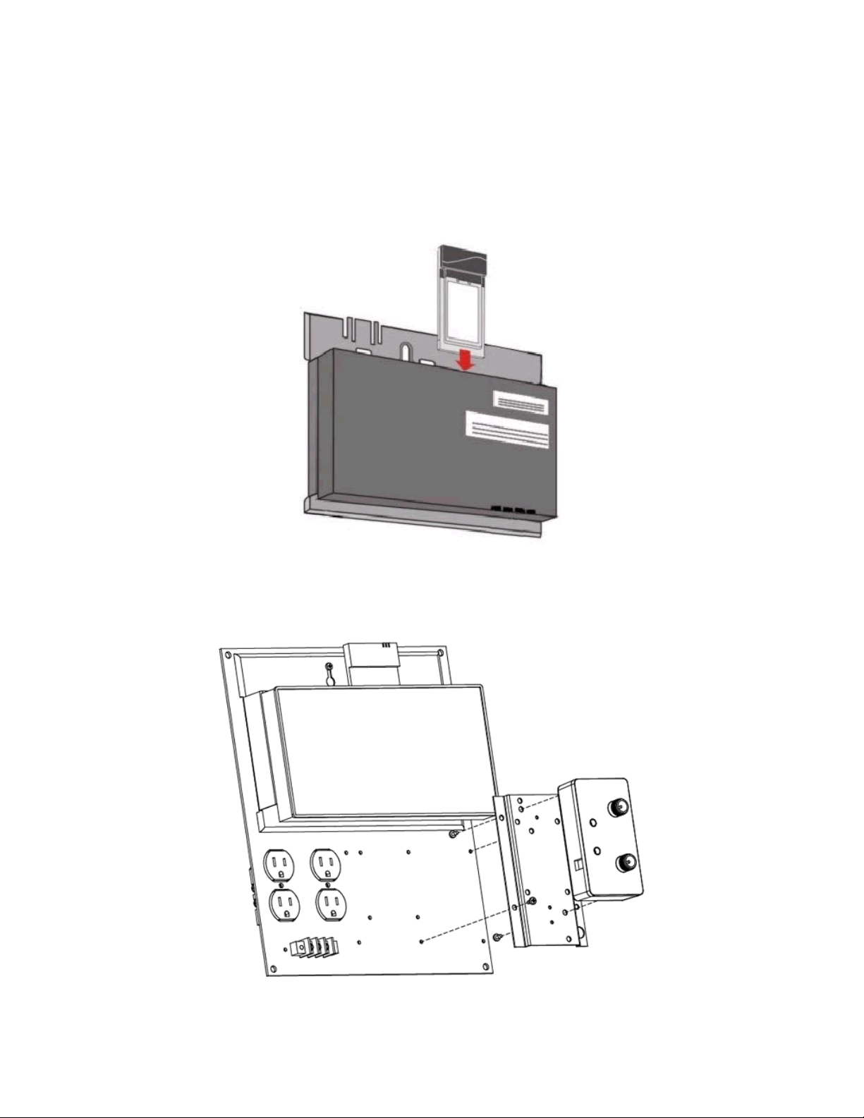
Slide the PC Card into either Slot A or Slot B.
Mount the amplifier into the enclosure as shown in below:

Connect the Pigtail Cable between the PC Card and the Amplifier input. Connect the
amplifier output to the Filter/ Lightning Protector, as required (see Appendix A).

Install the Antenna
NOTE: THE ANTENNA SYSTEM SHALL BE INSTALLED ONLY BY EXPERIENCED
ANTENNA INSTALLERS WHO ARE FAMILIAR WITH LOCAL BUILDING AND SAFETY
CODES, AND WHEREVER NECESSARY HAVE BEEN LICENSED BY APPROPRIATE
GOVERNMENT REGULATORY BODIES. FAILURE TO DO SO MAY VOID THE PRODUCT
WARRANTY, AS WELL AS EXPOSE THE END-USER TO LEGAL AND/OR FINANCIAL
LIABILITIES. HYPERLINK TECHNOLOGIES, ITS AGENTS, RESELLERS OR
DISTRIBUTORS, ARE NOT LIABLE FOR INJURY, DAMAGE, OR VIOLATION OF
GOVERNMENT REGULATIONS THAT MAY ARISE FROM FAILING TO COMPLY WITH THE
GUIDELINES DESCRIBED IN THIS DOCUMENT.
Mount the antenna according to the specific installation instructions for the model you
are installing. When choosing the antenna site you must observe the following exposure
limits:
The table contained in Appendix A of this manual identifies which antennas
are considered “fixed” and which are “mobile”. When thi s device is
installed as a fixed-mount application there is a minimum required
separation distance of one hundred (100) cm between the antenna and all persons
during normal operation. All mobile antennas must be mounted at a
minimum distance of 20 cm from users.
Once the antenna is installed connect the antenna to the amplifier and signal filter (as
applicable) using the antenna cable.
Connect the Ethernet cable to the AP. For configuration, use an Ethernet crossover and
connect directly to a PC.
Apply power to the Access Point unit. Check the diagnostic lights to ensure proper
connection.
You should now be ready to configure the Access Point.
Use the Scan Tool to determine the MAC and IP Address for the AP
Install the Scan Tool program on the PC you will be using to configure the AP over the
Ethernet segment.
Run the Scan Tool to determine the MAC Address and default IP Address for the AP.
You can use the Change Screen to change the IP Address, Subnet Mask and Gateway IP
Address as required.
For more detailed information about installing and running the Scan Tool, refer to the
AP-2000 User Guide.

Configure the AP’s Basic Wireless Operations Settings
The first time you connect to the AP using the HTTP interface, the Setup Wizard
launches automatically. It provides instructions for how to configure the Access Point’s
basic operating parameter including Network Name, IP Parameters, RF Parameters,
System Parameters and Management Passwords.
To access the setup screens, first open a Web browser on the configuration PC. It may be
necessary to disable the browser’s Internet Proxy Settings if set. Enter the IP Address of
the AP in the browser’s address line and press Enter.
When the Security screen appears you will need to log in. Leave the User Name b lank.
The default login password is public.
Using the configuration screens configure the basic operating parameters below:
Network Name (SSID): Enter a Network Name (between 2 and 31 characters long) for
the wireless network.
Auto Channel Select: You must disable this feature in order to manually set the
operating channel.
Frequency Channel: Select an authorized frequency channel based upon the specific
antenna used from the table in Appendix A.
Transmit Rate: Use the drop-down menu to select t he Auto-Fallback option.
WEP Encryption: Place a check mark in the box provided to enable WEP encryption.
See WEP Encryption in the AP -2000 User Guide for more information about WEP and
Encryption Keys.
Set Encryption Key 1: If you enable Encryption, co nfigure an Encryption Key. See
WEP Encryption in the AP -2000 User Guide for more information about WEP and
Encryption Keys.

Note: Additional advanced settings are available in the Wireless Interface Configuration
screen. See the Wireless (802.11b/g) Configuration information in the AP -2000 User
Guide for more information.
Review the Configuration Summary. If you want to make any additional changes, use
the navigation panel on the left-hand side of the screen to return to an earlier screen.
After making a change, click Save & Next to save the change and proceed to the next
screen.
When finished click Reboot on the Summary screen to restart the AP and apply your
changes.

Setting and Changing Security Passwords
Note: Configure the following passwords by entering a password in both the Password
field and the Confirm field:
SNMP Read Password – The password for read access to the AP using SNMP.
SNMP Read-Write Password – The password for read and write access to the AP using
SNMP.
SNMPv3 Authentication Password – The password used when sending authenticated
SNMPv3 messages. Secure Management (Services Tab) must be enabled in order to
configure SNMPv3.
SNMPv3 Privacy Password - The password used when sending encrypted SNMPv3
data. Secure Management (Services Tab) must be enabled in order to configure
SNMPv3.
Telnet (CLI) Password – The password for the CLI interface (via serial or Telnet).
HTTP (Web) Password – The password for the Web browser HTTP interface.
For security purposes make sure you set ALL PASSWORDS during installation.
IP Access Table
The Management IP Access Table limits in-band management access to the IP
addresses or range of IP addresses specified in the table. This feature applies to all
management options (SNMP, HTTP, and CLI) except for CLI management over the
serial port. To configure this table, enter the IP Addresses and IP Masks for the desired
addresses or range of addresses. Refer to the AP -2000 User Guide for further
information.
Configuring WEP and WPA
Each wireless interface can be configured to operate in WEP Encryption mode, 802.1x
Security Mode, Mixed (802.1x and WEP) Mode, WPA Mode and WPA-PSK (Pre-shared
Key) Mode. The Security mode selection is accessed through the Advanced
Configuration menus. Refer to the AP -2000 User Guide for further information.
Once the AP settings have been configured, apply power to the amplifier by plugging in
the appropriate DC power supply. Check the diagnostic LEDs to ensure proper
connection.

Running the Link Test Utility
You should now be ready to align the antenna using the Link Test utility. During the
Link Test, the Access Point and a selected Test Partner device exchange a series of
packets to test the strength and quality of the wireless connection. The Link Test utility
tab is accessible from the Monitor option.
Advanced Network Settings
The sytem should now be ready for advanced network configuration parameters. For
more information about the Advanced Network Settings, refer to the AP -2000 User
Guide.

AN/AN/AN/A
AN/AN/AN/A
AN/AN/A
For Amplifier(s): HA2401GI-XXX, HA2401G-XXX, where XXX stands for the amplifier power rating labeled in mW (see below)
Appendix A
FCC / IC Compliant Configurations - Channels of Operation
Antenna Model Antenna Type Gain (dBi) 29.2 29 28 27 26 24 23 20 18 17 14 17.5 (dBm)
1000 800 630 500 400 250 200 100 60 50 25 (mW) - as labeled
HG2401U whip/monopole 1 4-8 4-8 4-8 4-8 4-8 4-8 4-8 4-8 4-8 4-8 4-8 -
HG2402RD whip/monopole 2 4-8 4-8 4-8 4-8 4-8 4-8 4-8 4-8 4-8 4-8 4-8 -
HG2403RD whip/monopole 3 4-8 4-8 4-8 4-8 4-8 4-8 4-8 4-8 4-8 4-8 4-8 -
HG2403UR whip/monopole 3 4-8 4-8 4-8 4-8 4-8 4-8 4-8 4-8 4-8 4-8 4-8 - Channel
HG2404CU whip/monopole 3 4-8 4-8 4-8 4-8 4-8 4-8 4-8 4-8 4-8 4-8 4-8 - 1
RE05E whip/monopole 5 4-8 4-8 4-8 4-8 4-8 4-8 4-8 4-8 4-8 4-8 4-8 - 2
RE05U whip/monopole 5 4-8 4-8 4-8 4-8 4-8 4-8 4-8 4-8 4-8 4-8 4-8 1-11 3
HG2405 whip/monopole 5 4-8 4-8 4-8 4-8 4-8 4-8 4-8 4-8 4-8 4-8 4-8 - 4
HG2406U whip/monopole 6 4-8 4-8 4-8 4-8 4-8 4-8 4-8 4-8 4-8 4-8 4-8 - 5
HG2407U whip/monopole 7 N/A 4-8 4-8 4-8 4-8 4-8 4-8 4-8 4-8 4-8 4-8 - 6
HG2408U whip/monopole 8 N/A 4-8 4-8 4-8 4-8 4-8 4-8 4-8 4-8 4-8 4-8 - 7
HG2409U whip/monopole 8.5 N/A 4-8 4-8 4-8 4-8 4-8 4-8 4-8 4-8 4-8 4-8 - 8
HGV-2409U whip/monopole 8.5 N/A 4-8 4-8 4-8 4-8 4-8 4-8 4-8 4-8 4-8 4-8 - 9
HG2410U whip/monopole 10 N/A N/A 4-8 4-8 4-8 4-8 4-8 4-8 4-8 4-8 4-8 - 10
HG2412U whip/monopole 12 N/A N/A N/A 4-8 4-8 4-8 4-8 4-8 4-8 4-8 4-8 - 11
HG2415U-PRO whip/monopole 15 N/
HG2409P patch 8 N/A 4-6 4-6 4-6 4-6 4-6 4-6 4-6 4-6 4-6 4-6 -
HG2408P patch 8 N/A 4-6 4-6 4-6 4-6 4-6 4-6 4-6 4-6 4-6 4-6 -
HG2412P patch 12 N/A N/A 4-6 4-6 4-6 4-6 4-6 4-6 4-6 4-6 4-6 -
HG2414P patch 14 N/A N/A N/A 4-6 4-6 4-6 4-6 4-6 4-6 4-6 4-6 -
HG2416P patch 16 N/
HG2409Y Yagi-Uda 9 N/A 4-8 4-8 4-8 4-8 4-8 4-8 4-8 4-8 4-8 4-8 -
HG2412Y Yagi-Uda 12 N/A N/A 4-8 4-8 4-8 4-8 4-8 4-8 4-8 4-8 4-8 -
HG2415Y Yagi-Uda 14.5 N/
Configurations in BLACK can be used in either MOBILE OR FIXED MOUNTED Installations (FILTER REQUIRED)
Configurations in BLUE can be used in either MOBILE OR FIXED MOUNTED Installations (NO FILTER REQUIRED)
Configurations in RED can only be used in FIXED MOUNTED Installations (FILTER REQUIRED)
Configurations with N/A are NOT PERMISSIBLE, via. FCC 15.247(b)(4)(i)
Configurations with "-" are NOT PERMISSIBLE as they do not meet the FCC Part 15 restricted band limits
Amplifier Power Rating
4-8 4-8 4-8 4-8 4-8 4-8 4-8 -
4-6 4-6 4-6 4-6 4-6 4-6 4-6 -
4-8 4-8 4-8 4-8 4-8 4-8 4-8 4-8 -
Card Alone
Frequency (MHz)
2412
2417
2422
2427
2432
2437
2442
2447
2452
2457
2462

Minimum Separation Distance (cm)
Antenna Model Gain (dBi)
HG2401U 1
HG2402RD 2
HG2403RD 3
HG2403UR 3
HG2404CU 3
RE05E 5
RE05U 5
HG2405 5
HG2406U 6
HG2407U 7
HG2408U 8
HG2409U 8.5
HGV-2409U 8.5
HG2410U 10
HG2412U 12
HG2415U-PRO 15
HG2409P 8
HG2408P 8
HG2412P 12
HG2414P 14
HG2416P 16
HG2409Y 9
HG2412Y 12
HG2415Y 14.5
Configurations in BLACK Can be used in either MOBILE OR FIXED MOUNTED Installations
Configurations in RED can only be used in FIXED MOUNTED Installations
Configurations with N/A are not permissible, via. FCC 15.247(b)(4)(i)
Antenna Model Gain (dBi)
HG2401U 1
HG2402RD 2
HG2403RD 3
HG2403UR 3
HG2404CU 3
RE05E 5
RE05U 5
HG2405 5
HG2406U 6
HG2407U 7
HG2408U 8
HG2409U 8.5
HGV-2409U 8.5
HG2410U 10
HG2412U 12
HG2415U-PRO 15
HG2409P 8
HG2408P 8
HG2412P 12
HG2414P 14
HG2416P 16
HG2409Y 9
HG2412Y 12
HG2415Y 14.5
HG2424G 24
29.2 29 28 27 26 24 23 20 18 17 14 17.5
9.1 8.9 8.0 7.1 6.3 5.0 4.5 3.2 2.5 2.2 1.6 -
10.2 10.0 8.9 8.0 7.1 5.6 5.0 3.6 2.8 2.5 1.8 -
11.5 11.2 10.0 8.9 8.0 6.3 5.6 4.0 3.2 2.8 2.0 -
11.5 11.2 10.0 8.9 8.0 6.3 5.6 4.0 3.2 2.8 2.0 -
11.5 11.2 10.0 8.9 8.0 6.3 5.6 4.0 3.2 2.8 2.0 -
14.5 14.1 12.6 11.2 10.0 8.0 7.1 5.0 4.0 3.6 2.5 -
14.5 14.1 12.6 11.2 10.0 8.0 7.1 5.0 4.0 3.6 2.5 3.8
14.5 14.1 12.6 11.2 10.0 8.0 7.1 5.0 4.0 3.6 2.5 -
16.2 15.9 14.1 12.6 11.2 8.9 8.0 5.6 4.5 4.0 2.8 -
N/A 17.8 15.9 14.1 12.6 10.0 8.9 6.3 5.0 4.5 3.2 -
N/A 20.0 17.8 15.9 14.1 11.2 10.0 7.1 5.6 5.0 3.6 -
N/A 21.2 18.9 16.8 15.0 11.9 10.6 7.5 6.0 5.3 3.8 -
N/A 21.2 18.9 16.8 15.0 11.9 10.6 7.5 6.0 5.3 3.8 -
N/A N/A 22.4 20.0 17.8 14.1 12.6 8.9 7.1 6.3 4.5 -
N/A N/A N/A 25.1 22.4 17.8 15.9 11.2 8.9 8.0 5.6 -
N/A N/A N/A N/A 31.7 25.1 22.4 15.9 12.6 11.2 8.0 -
N/A 20.0 17.8 15.9 14.1 11.2 10.0 7.1 5.6 5.0 3.6 -
N/A 20.0 17.8 15.9 14.1 11.2 10.0 7.1 5.6 5.0 3.6 -
N/A N/A 28.2 25.1 22.4 17.8 15.9 11.2 8.9 8.0 5.6 -
N/A N/A N/A 31.7 28.2 22.4 20.0 14.1 11.2 10.0 7.1 -
N/A N/A N/A N/A 35.5 28.2 25.1 17.8 14.1 12.6 8.9 -
N/A 22.4 20.0 17.8 15.9 12.6 11.2 8.0 6.3 5.6 4.0 -
N/A N/A 28.2 25.1 22.4 17.8 15.9 11.2 8.9 8.0 5.6 -
N/A N/A N/A 33.5 29.9 23.7 21.2 15.0 11.9 10.6 7.5 -
29.2 29 28 27 26 24 23 20 18 17 14 17.5
0.208 0.199 0.158 0.126 0.100 0.063 0.050 0.025 0.016 0.013 0.006 -
0.262 0.250 0.199 0.158 0.126 0.079 0.063 0.032 0.020 0.016 0.008 -
0.330 0.315 0.250 0.199 0.158 0.100 0.079 0.040 0.025 0.020 0.010 -
0.330 0.315 0.250 0.199 0.158 0.100 0.079 0.040 0.025 0.020 0.010 -
0.330 0.315 0.250 0.199 0.158 0.100 0.079 0.040 0.025 0.020 0.010 -
0.523 0.500 0.397 0.315 0.250 0.158 0.126 0.063 0.040 0.032 0.016 -
0.523 0.500 0.397 0.315 0.250 0.158 0.126 0.063 0.040 0.032 0.016 0.035
0.523 0.500 0.397 0.315 0.250 0.158 0.126 0.063 0.040 0.032 0.016 -
0.659 0.629 0.500 0.397 0.315 0.199 0.158 0.079 0.050 0.040 0.020 -
N/A 0.792 0.629 0.500 0.397 0.250 0.199 0.100 0.063 0.050 0.025 -
N/A 0.997 0.792 0.629 0.500 0.315 0.250 0.126 0.079 0.063 0.032 -
N/A 0.045 0.889 0.706 0.561 0.354 0.281 0.141 0.089 0.071 0.035 -
N/A 0.045 0.889 0.706 0.561 0.354 0.281 0.141 0.089 0.071 0.035 -
N/A N/A 0.050 0.997 0.792 0.500 0.397 0.199 0.126 0.100 0.050 -
N/A N/A N/A 0.063 0.050 0.792 0.629 0.315 0.199 0.158 0.079 -
N/A N/A N/A N/A 0.100 0.063 0.050 0.629 0.397 0.315 0.158 -
N/A 0.997 0.792 0.629 0.500 0.315 0.250 0.126 0.079 0.063 0.032 -
N/A 0.997 0.792 0.629 0.500 0.315 0.250 0.126 0.079 0.063 0.032 -
N/A N/A 0.080 0.063 0.050 0.792 0.629 0.315 0.199 0.158 0.079 -
N/A N/A N/A 0.100 0.080 0.050 0.040 0.500 0.315 0.250 0.126 -
N/A N/A N/A N/A 0.126 0.080 0.063 0.792 0.500 0.397 0.199 -
N/A 0.050 0.997 0.792 0.629 0.397 0.315 0.158 0.100 0.079 0.040 -
N/A N/A 0.080 0.063 0.050 0.792 0.629 0.315 0.199 0.158 0.079 -
N/A N/A N/A 0.112 0.089 0.056 0.045 0.561 0.354 0.281 0.141 -
N/A N/A N/A N/A N/A 0.502 0.399 0.200 0.126 0.100 0.050 -
Amplifier Power Rating (dB)
RF Exposure (mW/cm^2)
Amplifier Power Rating (dB)
Card Alone
Card Alone
Configurations in BLACK Can be used in either MOBILE OR FIXED MOUNTED Installations (RF Exposure computed at 20 cm distance)
Configurations in RED can only be used in FIXED MOUNTED Installations (RF Exposure computed at 100 cm distance)
Configurations with N/A are not permissible, via. FCC 15.247(b)(4)(i)

Important Information
Your wireless system has been installed and configured by an RF professional to comply
with FCC Part 15 regulations. These limits are designed to provide reasonable
protection against harmful interference when the equipment is operated in a commercial
environment. This equipment generates, uses and can radiate radio frequency energy
and, if not installed and used in accordance with the installation and configuration
manual, may cause harmful interference to radio communications. Operation of this
equipment in a residential area is likely to cause harmful interference in which case the
end user will be required to correct the interference at their own expense.
Mo difications to this system including changing the antenna, power setting or transmit
channel may result in a non-compliant system, and should only be undertaken by
professional installers after reading the Installation Guide for this system.
For further information contact:
Hyperlink Technologies
Technical Support Dept.
1201 Clint Moore Road
Boca Raton, FL 33487
Email: support@hyperlinktech.com
This equipment complies with FCC radiation exposure
limits set forth for an uncontrolled environment when
installed as directed. When this device is installed as
a fixed-mount application there is a minimum required
separation distance of one hundred (100) cm between
the antenna and all persons during normal operation.
For mobile mounted antennas, the required separation
distance is a minimum of twenty (20) cm between the
antenna and all persons during normal use.
Installer: Please post this notice in a prominent location near the transmitter.
SAFETY NOTICE
 Loading...