

www.L-com.com
OUTDOOR INSTALLATION WARNING
IMPORTANT SAFETY PRECAUTIONS:
LIVES MAY BE AT RISK! Carefully observe these instructions and any special instructions that are included with the equipment you are installing.
IMPORTANT:
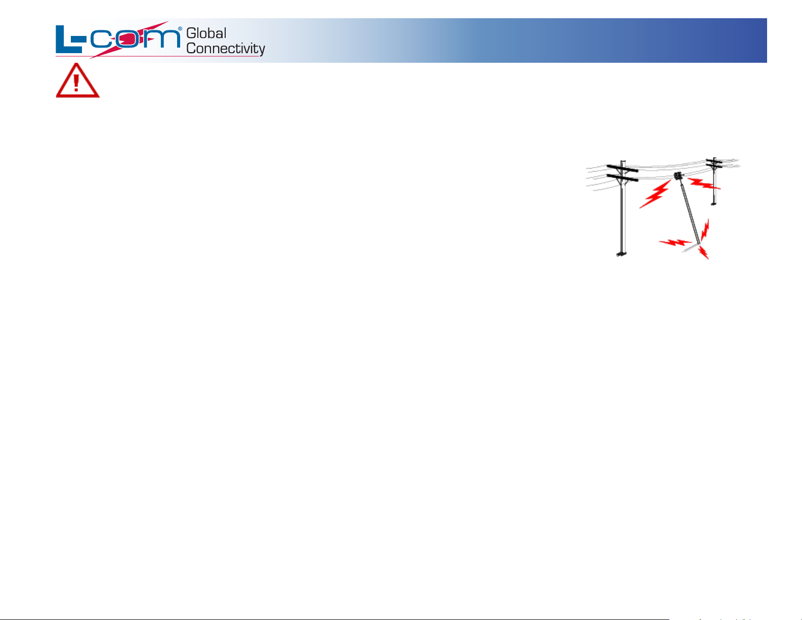
CONTACTING POWER LINES CAN BE LETHAL.
can be made. Antennas, masts, towers, guy wires or cables may lean or fall and contact these lines. People may be injured or
killed if they are touching or holding any part of equipment when it contacts electric lines. Make sure there is NO possibility
that equipment or personnel can come in contact directly or indirectly with power lines.
Assume all overhead lines are power lines.
The horizontal distance from a tower, mast or antenna to the nearest power line should be at least twice the total length of the
mast/antenna combination. This will ensure that the mast will not contact power if it falls either during installation or later.
Look over the site before beginning any installation, and anticipate possible hazards, especially these:
Make sure no power lines are anywhere where possible contact
TO AVOID FALLING, USE SAFE PROCEDURES WHEN WORKING AT HEIGHTS ABOVE GROUND.
• Select equipment locations that will allow safe, simple equipment installation.
• Don’t work alone. A friend or co-worker can save your life if an accident happens.
• Use approved non-conducting ladders and other safety equipment. Make sure all equipment is in good repair.
• If a tower or mast begins falling, don’t attempt to catch it. Stand back and let it fall.
• If anything such as a wire or mast does come in contact with a power line,
calling the power company.
• Don’t attempt to erect antennas or towers on windy days.
DON’T TOUCH IT OR ATTEMPT TO MOVE IT
. Instead, save your life by
MAKE SURE ALL TOWERS AND MASTS ARE SECURELY GROUNDED, AND ELECTRICAL CABLES CONNECTED TO ANTENNAS
HAVE LIGHTNING ARRESTORS.
connected to the antenna.
This will help prevent fire damage or human injury in case of lightning, static build-up, or short circuit within equipment
• The base of the antenna mast or tower must be connected directly to the building protective ground or to one or more approved grounding rods, using 1O AWG
ground wire and corrosion-resistant connectors.
• Refer to the National Electrical Code for grounding details.
• Lightning arrestors for antenna feed coaxial cables are available from HyperLink Technologies, Inc.
IF A PERSON COMES IN CONTACT WITH ELECTRICAL POWER, AND CANNOT MOVE:
DON’T TOUCH THAT PERSON, OR YOU MAY BE ELECTROCUTED.
•
• Use a non-conductive dry board, stick or rope to push or drag them so they no longer are in contact with electrical power.
• Once they are no longer contacting electrical power, administer CPR if you are certified, and make sure that emergency medical aid has been requested.
Copyright © This drawing is property of L-com Global Connectivity. All rights reserved.
WWW.L-COM.COM E-MAIL: SALES@L-COM.COM PHONE: 1-800-343-1455 FAX: 1-978-689-9484
© L-com, Inc. All Rights Reserved. L-com Global Connectivity and the L-com logo are registered marks.
L-COM, INC. 45 BEECHWOOD DRIVE NORTH ANDOVER, MA 01845
www.L-com.com
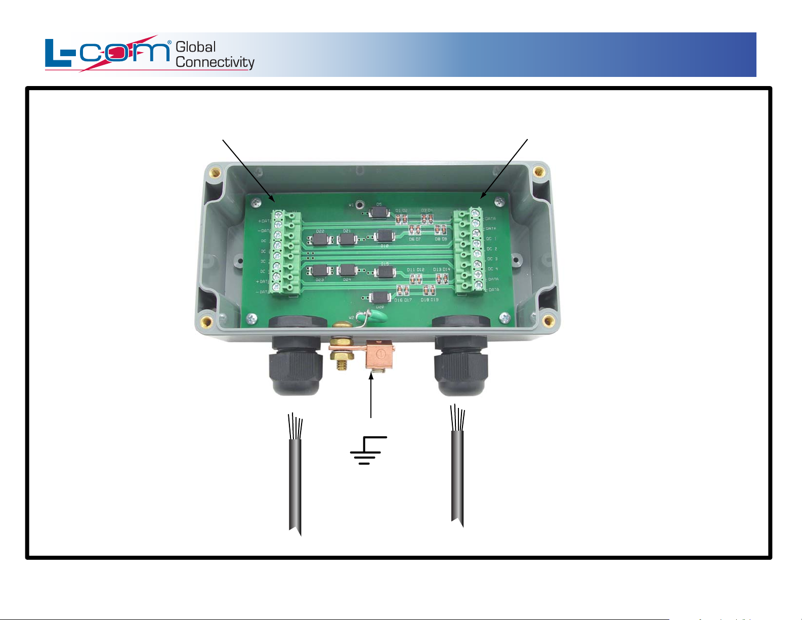
AL-CAT5EW Connection Diagram
Terminal Strip*
LINE SIDE
Terminal Strip*
*Unit provides protection
to both sides equally.
EQUIPMENT SIDE
AIP-00055 Rev. C – 09/06 Page 2/5
To Ground
CAT5e Cables
(Unterminated)
L-COM, INC. 45 BEECHWOOD DRIVE NORTH ANDOVER, MA 01845
WWW.L-COM.COM E-MAIL: SALES@L-COM.COM PHONE: 1-800-343-1455 FAX: 1-978-689-9484
© L-com, Inc. All Rights Reserved. L-com Global Connectivity and the L-com logo are registered marks.
Copyright © This drawing is property of L-com Global Connectivity. All rights reserved.

www.L-com.com
1. Position the suppressor with the strain reliefs down
when mounting.
2. The data cable is connected to the suppressor
via the terminal strips.
Install the data cable through the strain reliefs, strip
back cable jackets as needed and terminate the data
wires to the screw down terminal blocks (Pinouts
located next to terminal strip).
Terminal strips can be removed to ease wiring.
CAT5e Pinout: 1 - Data 1 +
2 - Data 1 3 - DC 1
4 - DC 2
5 - DC 3
6 - DC 4
7 - Data 1 +
8 - Data 1 -
LINE
AL-CAT5EW Installation Instructions
1
2
3
4
5
6
7
8
58 VOLT
PROTECTION
DEVICE
58 VOLT
PROTECTION
DEVICE
1
2
3
4
5
6
7
8
LINE
3. Adjust the cable inside the unit to ensure proper closing
of cover, then secure by tightening strain reliefs onto cables.
4. Attach cover using the provided hardware.
5. To ensure proper operation of suppressor,
install an earth ground to the external ground
lug on the unit.
Note: This unit provides Bi-Directional Protection,
input and output cables may be interchanged.
AIP-00055 Rev. C – 09/06 Page 3/5
L-COM, INC. 45 BEECHWOOD DRIVE NORTH ANDOVER, MA 01845
WWW.L-COM.COM E-MAIL: SALES@L-COM.COM PHONE: 1-800-343-1455 FAX: 1-978-689-9484
© L-com, Inc. All Rights Reserved. L-com Global Connectivity and the L-com logo are registered marks.
EARTH GROUND
Copyright © This drawing is property of L-com Global Connectivity. All rights reserved.

RJ45 Pin/Color
CAT5e Cable Reference for AL-CAT5EW
CAT5e (EIA 568-B) Cable
LINE
EQUIPMENT
www.L-com.com
RJ45 Pin/Color
1 WHT/ORG
2 ORG
5 WHT/BLU
4 BLU
7 WHT/BRN
8 BRN
3 WHT/GRN
6 GRN
RJ45 Pin/Color
1 WHT/GRN
2 GRN
5 WHT/BLU
4 BLU
7 WHT/BRN
8 BRN
3 WHT/ORG
6 ORG
DATA PAIR 1 +
DATA PAIR 1 DC 1
DC 1
DC 2
DC 2
DATA PAIR 2 +
DATA PAIR 2 -
DATA PAIR 1 +
DATA PAIR 1 DC 1
DC 1
DC 2
DC 2
DATA PAIR 2 +
DATA PAIR 2 -
AL-CAT5EW Lightning Protector
CAT5e (EIA 568-A) Cable
LINE
DATA PAIR 1 +
DATA PAIR 1 DC 1
DC 1
DC 2
DC 2
DATA PAIR 2 +
DATA PAIR 2 -
EQUIPMENT
DATA PAIR 1 +
DATA PAIR 1 DC 1
DC 1
DC 2
DC 2
DATA PAIR 2 +
DATA PAIR 2 -
1 WHT/ORG
2 ORG
5 WHT/BLU
4 BLU
7 WHT/BRN
8 BRN
3 WHT/GRN
6 GRN
RJ45 Pin/Color
1 WHT/GRN
2 GRN
5 WHT/BLU
4 BLU
7 WHT/BRN
8 BRN
3 WHT/ORG
6 ORG
AIP-00055 Rev. C – 09/06 Page 4/5
AL-CAT5EW Lightning Protector
Copyright © This drawing is property of L-com Global Connectivity. All rights reserved.
L-COM, INC. 45 BEECHWOOD DRIVE NORTH ANDOVER, MA 01845
WWW.L-COM.COM E-MAIL: SALES@L-COM.COM PHONE: 1-800-343-1455 FAX: 1-978-689-9484
© L-com, Inc. All Rights Reserved. L-com Global Connectivity and the L-com logo are registered marks.

www.L-com.com
AL-CAT5EW Dimensions
Cable Conduit
TOP VIEW
6.313"
Ground Clamp
3.157"
4.157"
5.840" (2X)
BOTTOM VIEW
.176" Dia. Mounting Holes (4x)
Mounting Screw (4x)
(#6 or M3.5 Pan Hd.)
.237"
.592"
1.973" (2X)
1.680"
AIP-00055 Rev. C – 09/06 Page 5/5
2.950"
SIDE VIEW
2.170"
.980" (2X)
Copyright © This drawing is property of L-com Global Connectivity. All rights reserved.
L-COM, INC. 45 BEECHWOOD DRIVE NORTH ANDOVER, MA 01845
WWW.L-COM.COM E-MAIL: SALES@L-COM.COM PHONE: 1-800-343-1455 FAX: 1-978-689-9484
© L-com, Inc. All Rights Reserved. L-com Global Connectivity and the L-com logo are registered marks.
(Cover Removed)
 Loading...