

Page 1

H.264 Digital Video/Audio Recorders
User’s Manual
Models:
16-CH
9-CH
Before attempting to connect or operate this product,
please read these instructions carefully and save this manual for future use.
Page 2
1
CAUTION
TO REDUCE THE RISK OF ELECTRIC SHOCK, DO NOT REMOVE COVER.
NO USER SERVICEABLE PARTS INSIDE.
PLEASE REFER SERVICING TO QUALIFIED SERVICE PERSONNEL.
NOTE: This equipment has been tested and found to comply with the limits for a
Class “A” digital device, pursuant to Part 15 of the FCC Rules. These limits are
designed to provide reasonable protection against harmful interference when the
equipment is operated in a commercial environment. This equipment generates,
uses and can radiate radio frequency energy and, if not installed and used in
accordance with the instruction manual, may cause harmful interference to radio
communications. Operation of this equipment in a residential area is likely to
cause harmful interference in which case the users will be required to correct the
interference at their own expense.
FCC Caution: To assure continued compliance, use only shielded interface cables
when connecting to computer or peripheral devices. Any changes or
modifications not expressly approved by the party responsible for compliance
could void the user’s authority to operate this equipment.
This Class A digital apparatus meets all the requirements of the Canadian
Interference Causing Equipment Regulations.
WARNING
TO PREVENT FIRE OR ELECTRIC SHOCK HAZARD, DO NOT EXPOSE THIS
APPLIANCE TO RAIN OR MOISTURE.
Page 3

2
LIMITATION OF LIABILITY
THIS PUBLICATION IS PROVIDED “AS IS” WITHOUT WARRANTY OF ANY KIND,
EITHER EXPRESS OR IMPLIED, INCLUDING BUT NOT LIMITED TO, THE IMPLIED
WARRANTIES OF MERCHANTIBILITY, FITNESS FOR ANY PARTICULAR PURPOSE,
OR NON-INFRINGEMENT OF THE THIRD P ARTY’S RIGHT.
THIS PUBLICATION COULD INCLUDE TECHNICAL INACCURACIES OR
TYPOGRAPHICAL ERRORS. CHANGES ARE ADDED TO THE INFORMA TION
HEREIN, AT ANY TIME, FOR THE IMPROVEMENTS OF THIS PUBLICATION
AND/OR THE CORRESPONDING PRODUCT(S).
DISCLAIMER OF WARRANTY
IN NO EVENT SHALL THE SUPPLIER BE LIABLE TO AN Y PARTY OR ANY PERSON,
EXCEPT FOR REPLACEMENT OR REASONABLE MAINTENANCE OF THE PRODUCT,
FOR THE CASES, INCLUDING BUT NOT LIMITED TO THE FOLLOWINGS:
ANY DAMAGE OR LOSS, INCLUDING BUT WITHOUT LIMITATION, DIRECT OR
INDIRECT, SPECIAL, CONSEQUENTIAL OR EXEMPLARY, ARISING OUT OF OR
RELATING TO THE PRODUCT;
PERSONAL INJURY OR ANY DAMAGE CAUSED BY INAPPROPRIATE USE OR
NEGLIGENT OPERATION OF THE USER;
UNAUTHORIZED DISASSEMBLE, REPAIR OR MODIFICATION OF THE PRODUCT
BY THE USER;
ANY PROBLEM, CONSEQUENTIAL INCONVENIENCE, OR LOSS OR DAMAGE,
ARISING OUT OF THE SYSTEM COMBINED WITH THE DEVICES OF THE THIRD
PARTY;
ANY CLAIM OR ACTION FOR DAMAGES, BROUGHT BY ANY PERSON OR
ORGANIZATION BEING A PHOTOGENIC SUBJECT, DUE TO VIOLATION OF
PRIVACY WITH THE RESULT OF THA T SURVEILLANCE-CAMERA ’S PICTURE,
INCLUDING SAVED DATA, FOR SOME REASON, BECOMES PUBLIC OR IS USED
FOR THE PURPOSE OTHER THAN SURVEILLANCE.
Page 4

3
PRECAUTIONS
Please refer all work related to the installation of this product to qualified service
personnel or system installers.
Do not operate the appliance beyond its specified temperature, humidity or power
source ratings.
Use the appliance at temperatures between 0
o
C ~ +45oC (32oF ~ 113oF) and humidity below
85%.
The input power source for this appliance is between 90 ~ 264 VAC, 47 ~ 63 Hz.
Performance and lifetime of hard disk drives are easily affected by heat (used at high
temperature). It is recommended to use this appliance at temperature between +20
o
C ~
+30
o
C (68oF ~ 86oF)
Handle the hard disk drives with care.
It is possible to damage them if they are moved while their mot ors are still running. Do no t
move them just after turning the power on or off (for around 30 seconds).
Protect the hard disk drives from static electricity .
Do not stack them or keep them upright.
Do not use an electric screwdriver to fix them.
Clean only with dry cloth.
Do not block any ventilation openings.
Do not use the appliance near any heat sources such as radiators, heat registers, stoves or
other apparatus that produce heat.
Protect the power cord from being stepped on or pinched particularly at plugs, convenient
receptacles and the points where they exit from the apparatus.
Do not drop metallic parts through slots. This could permanently damage the appliance.
Turn the power off immediately and contact qualified service personnel for service.
Handle the appliance with care. Do not strike or shake, as this may damage the appliance.
Do not expose the app lianc e to wa ter or mo istur e, nor t ry to op erate it in wet areas. Do take
immediate action if the appliance becomes wet. Turn the power off and refer servicing to
qualified service personnel. Moisture may damage the appliance and also cause electric
shock.
Do not use strong or abrasive detergents when cleaning the app lianc e body. When th e dirt is
hard to remove, use a mild detergent and wipe gently.
Do not overload outlets and extension cords as this may result in a risk of fire or electric
shock.
Please make a note of your settings and save them. This will help when you are required to
change the system configuration, or when unexpected failure or trouble occurs.
Distributing, copying, disassembling, reverse compiling, reverse engineering, and also
exporting in violation of export laws of the software provided with this product, is expressly
prohibited.
Page 5

4
Table of Contents
1. Product Overview
················································································
1.1 Features··························································································
2. Panels And Remote Controller·····························································
2.1 Front Panel······················································································
2.2 Back Panel······················································································
2.3 Remote Controller············································································
3. Installations·························································································
3.1 Basic Connections············································································
3.2 Optional Connections·······································································
4. Main Screen And Basic Operations
·······················································
4.1 Text Input························································································
4.2 Login And Logout············································································
4.3 Basic Operations··············································································
4.4 Digital Zoom···················································································
5. Menu Display·······················································································
5.1 Status Display··················································································
5.2 Volume Control···············································································
5.3 V ideo Adjustment············································································
5.4 VGA Display··················································································
5.5 Backup Device················································································
5.6 Software Upgrade (Administrator) ····················································
5.7 System Shutdown (Administrator) ····················································
6. Setup (Administrator)
·········································································
6.1 Pre-Camera Setup············································································
6.2 Camera Setup··················································································
6.2.1 V ideo Loss Setup······································································
6.2.2 Motion Setup···········································································
6.3 Alarm Setup····················································································
6.4 SEQ Display Setup··········································································
6.5 Scheduled Record Setup···································································
6.6 HDD Setup······················································································
6.6.1 HDD Format/Clear···································································
6.6.2 Advanced HDD Setup································································
6.6.3 Removable Hard Drive······························································
6.7 Password Setup················································································
6.8 System Setup···················································································
6.9 RS-232/422/485 Setup······································································
6.10 Network Setup···············································································
6.10.1 E-mail Setup··········································································
6
6
7
7
10
12
13
13
14
18
18
19
20
21
22
23
23
24
25
26
28
29
29
30
32
34
35
38
40
42
43
44
46
47
47
48
50
51
52
Page 6

5
6.10.2 Advanced Network Setup························································
7. PTZ Control·························································································
8. Search/Playback/Archive (Administrator/Supervisor) ·························
8.1 Search By Time···············································································
8.2 Search By Event / Log Display··························································
8.3 Search Archived Files ·······································································
8.4 Playback/Archive For Search By Ti m e ···············································
8.5 Playback/Archive For Search By Event··············································
8.6 Playback For Archived Files·····························································
8.7 Playback Procedures ·····························································
9. PC Remote Access················································································
10. 2G ~ 3.5G PDA/Mobile Phone Remote Access ····································
Appendix A – MS-Windows HEM player····················································
Appendix B – The mouse operation interface reference·································
Appendix C – Specifications·······································································
Appendix D – Times Zone Table·································································
Appendix E – Recording Table···································································
Appendix F – Compatible HDD List Table··················································
53
54
56
56
57
59
60
62
62
62
64
71
72
74
78
80
82
84
Page 7

6
1. Product Overview
The H.264 digital video/audio recorders are designed for use within a surveillance system and
are a combination of a hard disk recorder, a video multiplexer, and a web server. To achieve
the highest inter-connectivity and inter-operability, this series of digital video/audio recorders
are all based on industry-leading front-end to back-end surveillance infrastructure. With
state-of-the-art system architecture, powerful hardware compression/decompression engine,
and intelligent recording algorithms, sixfold operation can be easily achieved without
sacrificing the increasing demands of functionality, performance, reliability, and availability
in the surveillance industry.
1.1 Features
16/9 color and/or B/W cameras can be connected
H.264 Baseline Profile video compression/decompression with configurable quality
Hardware ADPCM audio compression/decompression -2 stereo audio input,2 audio
output
Real sixfold operation - simultaneous record, live, playback, backup, control, & remote
access
Record capabilities –
Full-D1: up to 60 (NTSC) / 50 (PAL) IPS for 16/9-CH models,
Half-D1: up to 120 (NTSC) / 100 (PAL) IPS for 16/9-CH models,
CIF: up to 240 (NTSC) / 200 (PAL) IPS for 16/9-CH models,
Live display, 30 (NTSC) / 25 (PAL) IPS, for each channel
Event recording, time-lapse recording or both
Playback search by time or event (alarm, motion, & video loss)
Versatile display formats: full-screen, 4, 7, 9, 10, 13, and 16 split windows
Digital zoom, X2 & X4
Intelligent motion detection with programmable area and sensitivity
Powerful alarm processor with configurable triggering conditions and reactions
Up to four hard disk drives
Video/audio backup to USB2.0 storage devices, including pen drive, DVD+RW, DVD+R,
and DVD-R
Internal DVD Models: Video/audio backup to internal DVD, including DVD+RW,
DVD+R, and DVD-R
Ethernet interface for remote access through web browser or proprietary remote software,
remote alarm notification, remote setup, and remote software upgrade
1 I.E. software for up to 4 DVRs
PTZ control capabilities & RS-422/RS-485 keyboard control capabilities
Multi-lingual support
Multi-level password and authentication key protection to ensure high degree of security
Page 8

7
2. Panels and Remote Controller
2.1 Front Panel
1. Front Door
Conceal Hard Disk Tray (and internal DVD for DVD models). For internal DVD, please
open the front door in order not to block the tray from ejecting, esp. while it’s in
backup process. Blocking the tray from ejecting may damage the DVD writer.
2. USB connector (USB)
Connect to USB 2.0 compatible storage device, such as USB 2.0 disk drive, DVD+RW,
card reader, etc.
3.
DVR ID Switch
Used to set the DVR ID (1-4) of this unit for one I/R remote controller to control up to 4
sets of digital video/audio recorders.
4. Alpha-numeric Buttons (1-9, 0, *, #)
Press these buttons for camera selection in most circumstances. These buttons can also
be used to enter text and number in the way similar to most of the mobile phones.
5. X2/GOTO Button
In PTZ control, press this button to move the camera to the preset position. In full
screen display, press this button for Digital Zoom (X2/X4).
6. MUTE/NEXT Button
In PTZ control, press this button for the next miscellaneous control. In the other screens,
press this button to mute the audio.
7. Alarm Reset Button
Press this button to cancel ala rm activation, and return the system to the condition befo re
the alarm was activated.
Page 9

8
8. SEARCH Button
Press this button to display the search menu in main screen display. In some dialogs,
this button is used as a miscellaneous function key.
9. CALL Button
Press this button to switch to or return from full screen display of the focus camera in
main screen display. In some dialogs, this button is used as a miscellaneous function
key.
10. SEQ Button
Press this button to switch to or return from SEQ display mode in main screen display.
In some dialogs, this button is used as a miscellaneous function key.
11. MODE Button
Press this button to toggle between live mode and playback mode in main screen display.
In some dialogs, this button is used as a miscellaneous function key.
12. LEDs
Indicators for POWER, Normal Recording, Alarm Recording, Net Link, and Net Active.
13. Copy Button (
)
Press this button to copy the playback images to the storage device connected to the USB
port. Press this button again to stop copying.
14. REC Button
Press this button to force manual recording. To stop manual recording, press it again.
15. ESC/PTZ Button
In main screen display, press this button to enter/exit PTZ control if the focus camera is a
PTZ camera. In the other displays, press this button to escape to the upper level display.
16. MENU Button
Press this button to display the main menu.
17. ENTER Button
This button is used as “enter” key in most circumstances. In PTZ control, this button is
used to start/stop the selected PTZ control mode.
18.
Left/Right Buttons (◄,►)
In PTZ control, press these buttons to pan the camera. In the other screens, press this
button to move the cursor or focus window.
19. Up/BS Button (▲/BS)
Press this button to move the cursor or focus window in most circumstances. In PTZ
Page 10

9
control, press this button to tilt up the camera. In text editing mode, this button is used
as “backspace” key.
20. Down/DEL Button (▼/DEL)
Press this button to move the cursor or focus window in most circumstances. In PTZ
control, press this button to tilt down the camera. In text editing mode, this button is
used as “del” key.
21. Fast Backward Button (
)
Press this button for fast backward playback.
22. Play/Pause Button (
)
Press this button to play the recorded images, or pause the playback.
23. Stop Button (
)
Press this button to stop the playback.
24. Single Step Button (
)
Press this button to play the recorded images frame by frame.
25. Fast Forward Button (
)
Press this button for fast forward playback.
26.
(Vol/Zoom) +/- Buttons (
/ / )
Press these buttons to change the volume in most circumstances. In PTZ control, press
these buttons to zoom in/out the camera.
27. (Split Windows) +/- Buttons (
)
In split-window display, press these buttons for next/previous split-window display. In
the others, press these buttons to change the contents.
28. Power Buttons
29. IR Window
This receives the IR signal from the remote control. Please make sure nothing is
blocking this window to ensure proper operation of your remote control.
Page 11

10
2.2 Back Panel
1.
Video Input Connectors (1-16/1-9)
Connect system cameras to these BNC connectors. The corresponding 75Ω termination
(see # 5) must be made unless the video output terminal is connected.
2. Video Output Connectors (1-16/1-9)
Connect these BNC connectors for looping the corresponding camera video inputs.
3. Stereo Audio Input Connectors (AUDIO IN 1-4)
These RCA connectors accept 2 stereo line-in audio signals supplied from external
devices such as microphone amplifiers.
4.
Audio Output Connectors (AUDIO OUT 1-2)
These connectors supply 2 line-out audio signals to external devices such as speakers.
Recorded audio will be supplied from AUDIO OUT during playback.
5. 75Ω termination
Set each of the DIP switches to ON unless the corresponding video output terminal is
connected.
6. Mouse plug port
For mouse connection.
7.
MAIN-AUX Connectors (MAIN-AUX IN/OUT)
Used to daisy-chain to TV monitor. MAIN-AUX OUT has the same output as MAIN
OUT, but can be switched off through RS-485 keyboard control.
8. Call Monitor Output Connector (CALL OUT)
Connect TV monitor to this BNC connector for call monitor display.
9. CALL-AUX Connectors (CALL-AUX IN/OUT)
Used to daisy-chain to TV monitor. CALL-AUX OUT has the same output as CALL
OUT, but can be switched off through RS-485 keyboard control.
10.
RS-232 Connector
Connect this connector to PTZ camera(s).
Page 12

11
11. RS-422/485 Selector Switch
Used to select RS-422/485 3-line or 2-line.
12. RS-422/485 Connector
Connect this connector to RS-42 2/485 compatible PTZ camera(s) or keyboard. Please
set the Selector Switch correctly. Please refer to the manuals that come with the
RS-422/485 compatible devices for the correct settings. Please refer to Appendix D
for
the Keyboard Control Protocol for the digital video recorder.
13. Alarm Input Connectors (ALARM IN 1-16)
Connect these connectors to external devices such as sensors or door switches.
14. Alarm Output Connectors (ALARM OUT 1-4)
Connect these connectors to 2 Normally Closed (NC) alarm outputs (1-2) and 2 Normally
Open (NO) alarm outputs (3-4).
15. Ethernet Connector
Connect this unit to a 10/100Base-T Ethernet network through this port.
16. NTSC/PAL Selector Switch
Set this unit to NTSC or PAL according to the local TV system.
17. USB Connector (USB)
Connect this port to USB 2.0 compatible storage device, such as USB 2.0 disk drive,
DVD+RW, card reader, etc.
18.
Cooling Fan
The cooling fan of the internal SPS (Switching Power Supply).
19.
Power Cord Inlet (AC IN)
Connect a power cord to this inlet. It accepts 90~264 VAC, 47~63 Hz power source.
20. VGA Connector
Connect VGA monitor to the VGA connector for main monitor display.
Page 13

12
2.3 Remote Controller
The remote controller is an optional accessory to ease the user’s operations. You can do all
the operations by the remote controller instead of the buttons on the front panel. The
effective distance is about 10 meters without any obstacle.
1. DVR ID Selection Buttons (DVR #1-4)
Press these buttons to select the DVR to be controlled by the remote controller. The
remote controller can control up to 4 sets of DVRs. Please make sure that the DVR ID
Switch for each of the DVRs is set correctly.
2.
The Other Buttons
Each of these buttons corresponds to one of those buttons on the front panel. Please
refer to the descriptions in Section 2.1.
DVR ID selection buttons
Page 14

13
3. Installations
The installations described below should be made by qualified service personnel or system
installers.
3.1 Basic Connections
Please refer to the following diagram for the connections.
Please make sure to set the NTSC/PAL Selector Switch on the back panel according to
the local TV system for the digital video/audio recorder to work correctly.
Cameras
Connect the camera video input connectors to the video outputs from system cameras or
other composite video sources via coaxial cables.
Main monitor
Connect the main monitor output connector (BNC or S-video) to a surveillance TV
monitor. The TV monitor displays selected live or recorded cameras in any available
split window format.
Hard disk drive(s)
Make sure to install at least one hard disk drive inside the hard disk tray.
Note: Each of the HDDs must be formatted before it can be used to record
video/audio. Please refer to Section 6.6.1 HDD Format/Clear
to format the
HDDs.
Page 15

14
Before connection After connection
Power
Plug 115 VAC or 230 VAC power source into the power socket.
3.2 Optional Connections
Audio inputs
Connect the audio input connectors to the audio line-outs from system cameras or other
audio sources. Please make sure to associate the audio inputs with the cameras in
Camera Setup as described in Section 6.2
accordingly.
Audio outputs
Connect the audio output connectors to the audio line-ins from speakers.
Alarm inputs
Each alarm input should have 2 or 3 wires. Those with 2 wires will either be Normally
Open (NO) or Normally Closed (NC). Those with 3 wires will allow the user to
choose. Connect two of those wires to the alarm input connector in the pairs indicated in
the diagram. Direction does not matter. There is availability for 8 possible alarm
inputs. When the alarm input has been connected, please configure the software system
accordingly as per Alarm Setup as described in Section 6.3
.
Alarm outputs
Connect the alarm outputs 1-2 to NC type of alarm signals, alarm outputs 3-4 to NO type
of alarm signals.
Ethernet
Connect the Ethernet connector to a standard twisted-pair Ethernet cable for remote
access via LAN or internet. Please make sure to setup the related configurations as
described in Section 6.10 Network Setup
.
Page 16

15
USB 2.0 disk drives, DVD+RW, card reader, etc.
If the user wants to use USB2.0 peripheral device to retrieve important recorded images
and/or audio, please connect it to the USB port connectors (one on the front panel, the
other on the back panel).
I/R remote controller
If there are more than one digital video/audio recorders to be controlled by the I/R remote
controller, please set the DVR ID on the front panel. One I/R remote controller can
control up to 4 sets of DVRs (with ID 1-4 individually).
Call monitor
Connect the call monitor output connector to a surveillance TV monitor. This monitor
displays the full screen images of the cameras asso ciated with the events (al arm or mo tion)
or the images from the installed ca meras sequ entially according to the SEQ Display Setup
(Section 6.4
) for call monitor.
PTZ Cameras
Connect the RS-232 connector or the RS-422/485 connector to PTZ camera(s) via the
appropriate cable. The system supports a variety of different PTZ cameras, including
Pelco D protocol Dome, Samsung SCC- 64 1P, Kalatel Cyber Dom e , Bosch A utoDome, etc.
But different PTZ cameras can coexist in a system only if they support the same protocol.
Please make sure to set the PTZ ID of the camera(s), and setup the camera (Section 6.1
),
and RS-232 or RS-422/485 (Section 6.9
) accordingl y. Pl ease also make su re to set the
RS-422/RS-485 Selector Switch if you are using the RS-422/485 port.
RS-485 keyboard or Terminal
Connect the RS-422/485 connector to a RS-485 keyboard controll er or VT-100 terminal
via the appropriate cables. Please refer to the following diagram for the pin definitions
of the RS-422/485 connector. Please make sure to set the RS-422/RS485 Selector
Switch and setup the RS-422/485 configurations as described in Section 6.9
accordingly.
Page 17

16
For 4-line devices (such as keyboard)
DVR Devices
For PTZ cameras
DVR Devices
MAIN-AUX monitor
Please refer to the diagram below to connect the MAIN-AUX monitor output connector to
a surveillance TV monitor or the MAIN-AUX monitor input connector of another digital
video/audio recorder. The MAIN-AUX monitor, if enabled, has the same output display
as the main monitor, and is typically used with RS-485 keyboard controller for distant
monitoring and control (e.g. in central control room).
N
/C N/C
GND
RxD+
RxD-
TxD+
TxD-
GND
Set this unit to 3-line
or 2-line according
to the connected
devices.
GND
TxDTxD+
RxDRxD+
GND
TxDTxD+
RxDRxD+
GND
RS485RS485+
GND
TxDTxD+
RxDRxD+
Page 18

17
CALL-AUX monitor
Please refer to the diagram below to connect the CALL-AUX monitor output connector to
a surveillance TV monitor or the CALL-AUX monitor input connector of another digital
video/audio recorder. The CALL-AUX monitor, if enabled, has the same output display
as the call monitor, and is typically used with RS-485 keyboard controller for distant
monitoring and control (e.g. in central control room).
Page 19

18
4. Main Screen And Basic Operations
The split-window screen, as shown above, is the main screen after system startup. There are
several types of split-window screens, including 1-Window, 4-Window, 7-Window,
9-Window, 10-Window, 13-Window, and 16-Window. The system will remember the last
one before normal shutdown (as described in Section 5.7
) of the system. In addition to the
split windows, the system time is displayed on the lower-left corner, the system state on the
lower-right corner, and the rolling screen messages, if shown while certain event occurs, on
the lower corner.
The system state, from right to left, are described as the followings:
(1) Normal recording percentage,
(2) Alarm recording percentage,
(3) X2 state – X1, X2, or X4,
(4) Manual record ON/OFF – Red Circle shown for ON,
(5) Backup state – Backup icon shown for backup,
(6) SEQ display ON/OFF or playback state – SEQ icon shown for SEQ display ON, other
icons for different playback states.
4.1 Text Input
There are certain circumstances where the system requires the user to enter text, such as
system login, camera title setup, and so on. Please follow the steps below to enter text:
(1) Press ENTER to edit the highlighted option. The flashing cursor will be shown to
indicate the editing point.
(2) Press ◄► to move the cursor to the left/right.
36%
Page 20

19
(3) Press code in text editing mode to change text case. (If this entry can accept number
only, pressing code will have no effects.) Indicators on the screen show the current
setting:
123 = Number only
abc = No capital letters
ABC = All capital letters
CODE = Internal code for the selected language, such as Chinese, Japanese, etc.
(4) Press a number key (1-9, 0) repeatedly until the character you want appears. (1 for 1 or
space, 2 for 2, a/A, b/B, or c/C, the others as shown on the keypad) If internal CODE is
selected, a
CODE box
will be shown (after the first code is entered) for each new code to
be entered. Please check the internal code table for the selected language. For 2-byte
code, e.g. Chinese or Japanese, the code accepted is from 0000 - FFFF.
(5) Press mark to bring up a list of punctuation marks and special characters. The
highlighted character in the list shows the selected one. Press ▲▼◄► to change the
selection.
(6) If you make a mistake, press BS to remove the character to the left of the cursor, or press
DEL
to delete the character at the current cursor position.
(7) In text editing mode, internal code box, and mark list, press ENTER to exit and save
changes, press
ESC
to exit without making changes.
4.2 Login And Logout
There are three password levels in the system, including Administrator (highest),
Supervisor, and Operator (lowest). If the user does not login the system, he/she will be
treated as “Guest” and can only view live video display.
The system allows up to 18 user accounts. The a dministrator can set up the login name and
password for each user. (Please refer to Section 6.7
for Password Setup.)
The Operator can operate live video display, the Supervisor live video display, image
playback and archive, and the Administrator everything.
To login/logout the system, press MENU in
split-window display to call up Menu display, and
then press ENTER when the highlighted option is
Login/Logout to enter Login/Logout display as
shown.
In Login/Logout display, follow the Text Input
method described in Section 4.1
to enter the Login name and Password, press ▲▼ to
highlight and select Login option, and then press ENTER to login the sy stem. If the u ser
wants to logout the system, just press ▲▼ to highlight and select Logout option , and then
press ENTER. Press ESC to exit without making changes.
Page 21

20
There is one factory-preset login name/password aa/11 at Administrator level. The user
can use it to login the system for the first time.
Should the user have forgotten all the administrator-level passwords, please contact the
local dealer or installer to recover from it.
4.3 Basic Operations
The basic user’s operations after he/she has logged into the system are described below:
Numeric (ENTER)
Press these buttons to change the camera for the focu s window. If the camera already
exists in the other window, the focus window will exchange with that window for the
cameras.
Alarm Reset
Press this button to cancel alarm activation, i.e. reset the alarm outputs and silence the
buzzer.
MODE (Administrator/Supervisor)
In split-window displ ay, press this button to change circular ly the live/play back mode for
the focus window and the other windows that form a rectangle on the screen. Please
note that the rectangle can contain at most 16/9 split windows.
SEQ
Press this button to switch to or return from SEQ display mode. In SEQ display mode,
each page in the sequence will b e shown for the preset page dwelling time sequentially,
and SEQ icon will be shown on the lower-right corner of the screen.
CALL
In split-window display, press this button to switch to or return from full screen display of
the focus camera.
SEARCH (Administrator/Supervisor)
In split-window display, press this button to display the search menu. The system will
remember the last one the user chose.
REC
Press this button to force manual recording. To stop manual recording, press it again.
All cameras will be recorded as if the scheduled record is A/V, and REC will be shown on
the lower-right corner of the screen if manual recording is ON.
MENU
In split-window display, press this button to display the main menu.
Page 22

21
PTZ
In split-window display, press this button to enter PTZ control mode if the focus camera is
a PTZ camera.
X2
In full screen display, press this button to enter Digital Zoom mode. Please refer to
Section 4.4 Digital Zoom
for the detailed operations in Digital Zoom mode.
▲▼◄►
Press these buttons to move focus. The title of the camera for the focus window is
highlighted as shown on the screen.
Vol+/- (
/ ), MUTE
Press these buttons to control the volume.
+/-
Press these buttons to circulate up/down among the available split-window displays.
4.4 Digital Zoom
The system supports X2/X4 Digital Zoom fun ction. To use this function, press X2 button in
full screen display to enter Digital Zoom mode. There will be a zoom window shown in the
video window as shown. The zoom window (a) will always be shown at zoom factor X1, (b)
can be shown or hidden at zoom factor X2, and (c) will never be shown at zoom factor X4.
The operations in Digital Zoom mode are as below:
▲▼◄►
Press these buttons to
(a) move the zoom window if it’s shown in the video window, or
(b) navigate the video window around if the zoom factor is X2 or X4.
Page 23

22
ENTER
Press this button to zoom in the zoom window, from X1 to X2 or from X2 to X4, if the
zoom window is shown in the video window.
X2
Press this button to
(a) show/hide the zoom window if the current zoom factor is X1/X2, or
(b) zoom out the video window back to zoom factor X1 if the current zoom factor is X4.
ESC
Press this button to escape from Digital Zoom mode, and return to normal full screen
display. The video window will always return to zoom factor X1.
5. Menu Display
In split-window display, press MENU to call up
Menu display as shown.
There are a variety of displays under Menu
display. In Menu display and all the
subsequent displays, the items enabled are
shown in black-colored text, and those disabled
in white-colored text. Please refer to
Appendix B
for the Structure Of Menu Displays.
Please refer to Section 4.2
for Login/Logout
display.
The user’s operations are described as the followings:
▲▼
Press these buttons to change the highlighted item.
ENTER
Press this button to enter the detailed display of the highlighted option. For the details of
each option, please refer to the following sections.
ESC
Press this button to escape from Menu display, and return to spli t-window display.
Page 24

23
5.1 Status Display
In Menu display, press ▲▼ to change the highlighted option to Status, and then press
ENTER to call up Status display as shown.
Status display includes Alarm Recording Status, Normal Recording Status, Camera Status,
Alarm Input Status, Product Serial Number, and Product Version Number. Press ESC to
escape from Status display, and return to Menu display.
5.2 Volume Control
In Menu display, press ▲▼ to change the
highlighted option to Volume, and then press
ENTER to call up Volume Control display as
shown.
The general operations are as below:
▲▼◄►
Press these buttons to select the items.
ESC
Press this button to escape from this sc reen, and return to Menu disp lay. If th e contents
have been modified, a Save dialog will be shown to ask the user to save the changes,
press ENTER to exit and save, ESC to exit without saving.
Following is a brief description for each item and its specific operations:
Mute – to mute the selected audio channel. Press ENTER to check/uncheck this item.
The default setting is “-” - unchecked.
Volume – the volume of the selected audio channel. Press +/- buttons to change the
value (1-20).
Page 25

24
5.3 Video Adjustment
In Menu display, press ▲▼ to change the highlighted option to Video Adjustment, and then
press ENTER to call up Vi deo Adjustment display as shown.
There are 4 items which can be adjusted, including Brigh tness, Contrast, Hu e, and Satu ration.
The operations are as below:
▲▼
Press these buttons to select the items.
ENTER
Press these buttons to change the camera.
+/-
Press these buttons to adjust the selected item.
SEQ
Press this button to reset the settings for this camera to factory default values.
CALL
Press this button to reset the settings for all cameras to factory default values.
MODE
Press this button to restore the values.
ESC
Press this button to escape from this screen, and return to Menu display. The settings
will be saved for future reference.
Page 26

25
5.4 VGA Display
In Menu display, press ▲▼ to change the highlighted option to VGA Display, and then press
ENTER to call up VGA Display dialog as shown.
There are 5 items which can be adjusted, including Resolution (1280x1024, 1024x768,
800x600, 640x480), Brightness, Contrast, Hue, and Saturation. The operations are as
below:
▲▼
Press these buttons to select the items.
+/-
Press these buttons to adjust the selected item.
MODE
Press this button to restore Brightness, Contrast, Hue, and Saturation to factory default
values.
ESC
Press this button to escape from this sc reen, and return to Menu disp lay. If th e contents
have been modified, a Save dialog will be shown to ask the user to save the changes,
press ENTER to exit and save, ESC to exit without saving.
Page 27

26
5.5 Backup Device
In Menu display, press ▲▼ to chang e the highlighted option to Backup Device, and then
press ENTER to call up Backup Device display as shown below.
The system supports internal DVD for Internal DVD models and a variety of USB 2.0
storage devices, including Storage Disk such as USB 2.0 storage disk drives and DVD Disc
(including DVD+RW, DVD+R, and DVD-R). (DVD-RW is not supported.) The
operations are as below:
▲▼◄►
Press these buttons to select the items.
ESC
Press this button to escape from this screen, and return to previous display.
MODE
Eject the tray and disconnect. (for Internal DVD only)
SEQ
Load the tray and connect. (for Internal DVD only)
Connect/Disconnect – If the specific backup device is disconnected (as shown in Current
Status), please plug the USB device in one of the USB ports of th e system and/o r insert a
DVD for DVD device, and then press
ENTER
to command the system to connect with
the device. If the specific device is already connected (EX. Read/write, as shown in
Current Status), please press ENTER to command the system software to disconnect with
the device, and then unplug the backup device from the backup port.
Note 1: Please DO NOT format the DVD disc for better performance and compatibility.
Note 2: Before using USB pen drive, please format it to FAT32 file system by
MS-Windows.
Note 3: The backup device has to be connected by the system software before it can be
used to read/write.
Page 28

27
Note 4: Some backup devices may have compatibility problems. Please contact your
local dealer or installer for the supported devices.
Note 5: For internal DVD, please open the front door in order not to block the tray from
ejecting, esp. while it’s in backup process. Blocking the tray from ejecting
may damage the DVD writer.
Backup
Press ENTER when this item is selected to backup the configurations of this unit to the
corresponding USB device.
Restore
Press ENTER when this item is selected to restore the configuration files in the
corresponding USB device to this unit.
Some USB 2.0 Devices Tested
USB-Storage Enclosures 5.25” –
Macpower’s Alumni Prefect USB 2.0 - PF-U2MS.
USB-Disk Storage –
Adata C801-8G, C702-16G, classic series 4GB
Transcend’s JetFlash 150/V60 Series,
Apacer’s Handy Steno AH220,
Pretec’s i-Disk Wave 512M-Black
Kingston’s DataTraveler USB Flash Driver(DTI/512FE)
SanDisk’s Cruzer micro USB Flash Driver
Sony’s MICRO VAULT Classic Series
DVD Writer –
Asus DRW-1608P Series,
Pioneer DVR-A11 Series, DVR-116BXL
LITEON Light Scribe DVD Writer Model SHM-165H6S Series, DH-20A4P39C
Sony DVD/CD Rewritable Drive Model DRX-810UL Series, DRU-V200A-BR
NEC DVD/CD Rewritable Drive Model ND-4550A Series.
HP dvd9404e External 18X Super Multi DVD Writer Series.
Some DVD Discs Tested – Only single-side, single-layer disc is supported
Infomedia DVD+R 16X
Mitsubishi DVD+RW 1-4X
Philips DVD+RW 1-4X
Ritek DVD-R 8X
Ritek DVD+RW 1-4X
Page 29

28
Verbatim DVD+RW 1-4X
5.6 Software Upgrade (Administrator)
In Menu display, press ▲▼ to change the highlighted option to Software Upgrade, and then
press ENTER to call up Software Upgrade display as shown.
The operations are as below:
▲▼◄►
Press these buttons to select the items.
ESC
Press this button to escape from this screen, and return to Menu display.
Following is a brief description for each item and its specific operations:
USB Device – press ENTER to call up USB Device dialog (if there’s no USB device
connected).
Disk Storage
– to select the disk storage to upgrade. Press
+/-
buttons to select the
available storage.
Upgrade File
– press
ENTER
to start the upgrade process when the highlighted file is a
correct upgrade file. A confirmation dialog will be shown on the screen, press ENTER
to confirm to upgrade the system software.
Note : After the software is upgraded, the system will restart immediately. The split
window display will be shown after restart, please wait a moment.
Page 30

29
5.7 System Shutdown (Administrator)
In Menu display, press ▲▼ to change the highlighted option to Shutdown, and then press
ENTER to shutdown the system. A confirmation dialog will be shown on the screen, press
ENTER to confirm the shutdown. The system will save all the file s and all the states, and
then display a power-off message in the rolling screen message area. The user may power
off the system safely when the power-off message is shown.
6. Setup (Administrator)
In Menu display, press
▲▼
to change the highlighted option to
Setup
, and then press
ENTER to call up Setup Menu display as shown. (To enter Setup Menu display of the
system, please login as Administrator first.)
The user’s operations are described as the
followings:
▲▼
Press these buttons to change the highlighted
item.
ENTER
Press this button to enter the setup of the
highlighted option. For the details of each
option, please refer to the following sections.
ESC
Press this button to escape from Setup Menu display,
and return to Menu display.
Page 31

30
If the user wants to reset all the settings to factory default values, he/she may press ▲▼ to
change the highlighted option to Factory Default s, and then press ENTER. A confirmation
dialog will be shown, press ENTER again to make the changes, ESC to not do it.
6.1 Pre-Camera Setup
In Setup Menu display, press ▲▼ to change the highlighted option to Pre-Camera, and then
press ENTER to call up Pre-Camera Setup display as shown.
There are up to 16, 9, or 4 cameras which can be connected to th e system. The Pre-Ca mera
Setup allows th e administrator to defi ne some fundamental attributes, which may relate one
camera to the others, for all the installed camera s.
The general operations are as below:
▲▼◄►
Press these buttons to select the items. The display will scroll up/down if the selected
item is not shown on the screen.
Numeric (ENTER)
Press these buttons to select the camera.
ESC
Press this button to escape from this screen, and return to Setup Menu display. If the
contents have been modified, a Save dialog will be shown to ask the user to save the
changes, press ENTER to exit and save, ESC to exit without saving.
Following is a brief description for each item and its specific operations:
REC Resolution – the record resolution for all the cameras in the system. For NTSC, it
can be 720x480, 720x240, or 360x240 ; for PAL, 720x576, 720x288, or 360x288. Press
+/-
buttons to select the resolution.
Page 32

31
Installed – whether this camera is installed or not. If installed, the following items will
be settable. Press ENTER to check/uncheck this item. The default setting is “ˇ” checked.
PTZ ID
– the PTZ ID of this camera if it’s a PTZ camera. The PTZ ID has to be
consistent with the setting of this camera. Please refer to the manual of the camera for
the ID setting. Press +/- buttons to change the value (N/A or 0-255). The default
setting is “
N/A
” – Not Available, which means that it’s not a PTZ camera.
Group – the group which the camera belongs to if its record resolution is 360x240 or
360x288. It’s used to maximize the record capacity of the system. Please refer to the
table below for the maximum number of cameras in a group. None-selectable groups
will be disabled and grayed. Please press ▲▼◄► buttons to highlight the group, and
then press ENTER to select the group of the camera.
TV system Record
Resolution
Max. number of cameras
in a group
720x480 N/A
720x240 N/A
NTSC
360x240
2
720x576 N/A
720x288 N/A
PAL
360x288
2
Please note that the cameras in the same group will have the same record attributes such
as record quality, record IPS, etc.
Page 33

32
6.2 Camera Setup
In Setup Menu display, press ▲▼ to change the highlighted option to Camera, and then
press ENTER to call up Camera Setup display as shown.
The Camera Setup al lows the administrato r to define the attribu tes for each camera. There
are up to 16, 9 cameras which can be connected to the system.
The general operations are as below:
▲▼◄►
Press these buttons to select the items. The display will scroll left/right if the selected
item is not shown on the screen.
Numeric (ENTER)
Press these buttons to select the camera.
COPY (
)
Press this button to copy all the settings - excluding detailed Motion settings, Video Loss
settings, Title/Audio - of the focus camera to all the following cameras. (EX. focus
camera is 5, its settings will be copied to those of cameras 6-16.)
ESC
Press this button to escape from this screen, and return to Setup Menu display. If the
Save dialog is shown, press ENTER to exit and save, ESC to exit without saving.
Following is a brief description for each item and its specific operations:
Title
– The title (Max. 8 characters) of this camera. Please follow the Text Input method
described in Section 4.1
to modify this item.
Page 34

33
Video Loss Settings.. – used to setup the action settings when video loss is detected for
this camera. Press ENTER in Settings.. to call up Video Loss Setup display for the
camera. Please refer to Section 6.2.1
for the details.
Motion Detection – whether the motion detection of this camera is enabled or not.
Press ENTER to check/uncheck this item. The default setting is “ˇ” - checked.
Motion Settings.. – used to setup the Motion Detection setting, for this camera. Press
ENTER
in
Settings..
to call up Motion Setup display for the camera. Please refer to
Section 6.2.2
for the details.
Covert
– covert or not. If th e camera is covert, the video of this camera can on ly be
seen if the user has logged in as Administrator. Press ENTER to check/uncheck this
item. The default setting is “–” - unchecked.
Call By Event – whether to switch the call monitor to the video of this camera if certain
event occurs for this camera. There are 4 options, including Off, Motion, Alarm, and
(Motion & Alarm). Press +/- buttons to select one.
Dwell Time – the dwell time if Call By Event is set to Motion, Alarm, or Both. Press
+/- buttons to adjust the value (3-60 seconds, discrete).
Audio – the AUDIO IN corresponding to this camera. The audio data for the select ed
AUDIO IN will be recorded with the video data for this camera. Press +/- buttons to
select none (N/A) or AUDIO Inputs (1/2, 3/4). The default setting is “N/A”.
Record Quality – the record quality for this camera. Press +/- buttons to select the
value (1-9, with 1 the lowest (rough) quality, 9 the highest (fine) quality).
Event Record IPS – the IPS (Images Per Second) for this camera if certain event
(Motion, Alarm) occurs for this camera. This camera will be recorded at this rate for
Post-record time since the event occurs. (Please refer to the following sections for
Post-record time.) Press +/- buttons to select the value (0 – 25 (PAL) / 30 (NTSC),
discrete).
Pre-record IPS – the pre-record IPS for this camera if certain event (Video Loss, Motion,
Alarm) occurs for this camera. This camera is recorded at this rate fo r Pre-record time
before the event occurs. (Please refer to the following sections for Pre-record time.)
Press +/- buttons to select the value (0 – Event Record IPS for this camera, discrete).
Normal Record IPS – the normal record IPS for this camera. This camera will be
recorded at this rate if no event occurs. Press +/- buttons to select the value (0 –
Pre-record IPS for this camera, discrete).
Page 35

34
6.2.1 Video Loss Setup
In Camera Setup, press ENTER to call up Video Loss Setup of the selected camera as shown
when the highlighted option is Video Loss Settings.. of the camera to setup. The Video
Loss Setup allows the administrator to define how the system responds to the detected video
loss for the camera.
The general operations are as below:
▲▼
Press these buttons to select the items.
Numeric (ENTER)
Press these buttons to select the camera.
COPY (
)
Press this button to copy the Video Loss settings of the focus camera to all the following
cameras. (EX. focus camera is 5, its Video Loss settings will be copied to those of
cameras 6-16.)
ESC
Press this button to escape from this screen, and return to Camera Setup display. If the
Save dialog is shown, press ENTER to exit and save, ESC to exit without saving.
Following is a brief description for each item and its specific operations:
Duration – response duration to define at most how long (in seconds) the Alarm Out
relay and the Buzzer will keep being triggered after video loss is detected for this camera.
However, the Alarm Out relay and the Buzzer will be reset immediat ely once the camera
returns to normal. Press +/- buttons to ad ju st the value (3 seconds - 60 minutes, discrete,
‘-‘ for ‘Forever’).
Pre-record – to define how long before video loss is detected this camera shall be
intensively recorded at Pre-record IPS. Press +/- buttons to adjust the value (0-60
seconds, discrete). Please note that the actual pre-record time may be shorter than the
value set if the total size of the pre-record pi ctures exceeds the pre-record buffer size of
the system.
Page 36

35
Alarm Out – to define which Alarm Output will be triggered when video loss of this
camera is detected. Press +/- buttons to select none (N/A) or one of the Alarm Outputs
(1-4).
Buzzer – to activate the internal Buzzer or not when video loss of this camera is detected.
Press ENTER to check/uncheck this item. The default setting is “ˇ” - checked.
Log – to log to event logs or not. Press ENTER to check/uncheck this item. The
default setting is “ˇ” - checked.
Screen Message – to display the event message on the screen or not. Press ENTER to
check/uncheck this item. The default setting is “ˇ” - checked.
E-mail
– to send the event e-mail to remote station or not. The e-mail will be sent to the
predefined receivers at the moment when the event is triggered. Press ENTER to
check/uncheck this item. The default setting is “–” - unchecked.
6.2.2 Motion Setup
In Camera Setup, press ENTER to call up Motion Setup as shown when the highlighted
option is Motion Settings.. of the camera to setup. The Motion setup allows the
administrator to define how the system responds to the detected motion for the camera.
The general operations are as below:
▲▼◄►
Press these buttons to select the items.
Numeric (ENTER)
Press these buttons to select the camera.
COPY (
)
Press this button to copy the Motion settings, including Detection settings, of the focus
camera to all the following cameras. (EX. focus camera is 5, its Motion settings will be
copied to those of cameras 6-16.)
Page 37

36
ESC
Press this button to escape from this screen, and return to Camera Setup display. If the
Save dialog is shown, press ENTER to exit and save, ESC to exit without saving.
Following is a brief description for each item and its specific operations:
Duration – response duration to define at most how long (in seconds) the Alarm Out
relay and the Buzzer will keep being triggered after motion is detected for this camera.
However, the Alarm Out relay and the Buzzer will be reset immediat ely once the camera
returns to normal. Press +/- buttons to ad ju st the value (3 seconds - 60 minutes, discrete,
‘-‘ for ‘Forever’).
Goto Preset – to define the preset position to go to if motion is detected and this camera
is a PTZ camera. For more details about preset locations, please refer to Chapter 7 PTZ
Control.
Pre-record – to define how long before motion is detected this camera shall be
intensively recorded at Pre-record IPS. Press +/- buttons to adjust the value (0-60
seconds, discrete). Please note that the actual pre-record time may be shorter than the
value set if the total size of the pre-record pi ctures exceeds the pre-record buffer size of
the system.
Post-record – to define how long after motion is detected this camera shall be intensively
recorded at Event Record IPS. Press +/- buttons to adjust the value (0 second - 60
minutes, discrete).
Alarm Out – to define which Alarm Output will be triggered when motion of this camera
is detected. Press +/- buttons to select none (N/A) or one of the Alarm Outputs (1-4).
Buzzer – to activate the internal Buzzer or not when motion of this camera is detected.
Press ENTER to check/uncheck this item. The default setting is “ˇ” - checked.
Log – to log to event logs or not. Press ENTER to check/uncheck this item. The
default setting is “ˇ” - checked.
Screen Message – to display the event message on the screen or not. Press ENTER to
check/uncheck this item. The default setting is “ˇ” - checked.
E-mail – to send the event e-mail to remote station or not. The e-mail will be sent to the
predefined receivers when the ev ent is triggered. Pre ss ENTER to check/uncheck this
item. The default setting is “–” - unchecked.
Detection Settings..
– used to setup the motion detection settings, including detection
area and sensitivity, when motion is detected for this camera. Press ENTER in Settings..
to call up Motion Detection Setup (as shown) for this camera. In Motion Detection
Setup, the video area is divided into many small grids, and the area with
transparent
grids is the area which will be detected for motion, while gray gr ids not detected for
motion. Besides, there is a (green) Mask window.
Page 38

37
Following is a brief description for the operations:
Numeric
Press these buttons to select the camera.
▲▼
◄►
Press these buttons to move the Mask window.
+/-
Press these buttons to resize the Mask window.
ENTER
Press this button to set/reset the area under the Mask window.
MODE
Press this button to set/reset the whole video area.
SEQ
Press this button to decrease the sensitivity, from 10 – 1, for the motion detection of
this camera.
CALL
Press this button to increase the sensitivity, from 1 – 10, for the motion detection of
this camera.
SEARCH
Press this button to test the motion detection of this camera. The detected motion
will be shown on the screen. Press this button again to stop testing.
ESC
Press this button to escape from Motion Detection Setup, and return to Motion Setup.
Page 39

38
6.3 Alarm Setup
In Setup Menu display, press ▲▼ to change the highlighted option to Alarm, and then press
ENTER to call up Alarm Setup display as shown. The Alarm Setup allows the
administrator to define the attributes for each alarm input, and the actions if it’s triggered.
There are up to 16 alarm inputs which can be connected to the system.
The general operations are as below:
▲▼◄►
Press these buttons to select the items. The display will scroll left/right if the selected
item is not shown on the screen.
Numeric (ENTER)
Press these buttons to select the alarm input.
COPY (
)
Press this button to copy the settings of the focus alarm in put to all the following alarm
inputs. (EX. focus alarm input is 5, its settings will be copied to those of alarm inputs
6-16.)
ESC
Press this button to escape from this screen, and return to Setup Menu display. If the
Save dialog is shown, press ENTER to exit and save, ESC to exit without saving.
Following is a brief description for each item and its specific operations:
Normal State – press +/- buttons to select N/A, Close or Open. Pl ease check the signal
type, normally close or normally open, connected to the alarm input terminal on the rear
panel of the system. If the re’s no signal connected, please select N/A – Not Available,
and the following items will not be settable. The default setting is Open.
Focus Camera – the camera corresponding to this alarm input.
Page 40

39
Duration – response duration to define at most how long (in seconds) the Alarm Out
relay and the Buzzer will keep being triggered after this alarm input is triggered.
However, the Alarm Out relay and the Buzzer will be re set immediately once this alarm
input returns to normal. Press +/- buttons to adjust the value (3 seconds - 60 minutes,
discrete, ‘-‘ for ‘Forever’).
Goto Preset – to define the preset position to go to for the Focus Camera if this alarm
input is triggered and the Focus Camera is a PTZ camera. For more details about preset
locations, please refer to Chapter 7 PTZ Control.
Pre-record – to define how long before this alarm input is triggered the Focus Camera
shall be intensively recorded at Pre-record IPS. Press
+/-
buttons to adjust the value
(0-60 seconds, discrete). Please note that the actual pre-record time may be shorter than
the value set if the total size of the pre-record picture s exceeds the pre-record buffer size
of the system.
Post-record
– to define how long after this alarm input is triggered the Focus Camera
shall be intensively recorded at Event Record IPS. Press +/- buttons to adjust the value
(0 second - 60 minutes, discrete).
Alarm Out – to define which Alarm Output will be triggered when this alarm input is
triggered. Press
+/-
buttons to select none (N/A) or one of the Alarm Outputs (1-4).
Buzzer – to activate the internal Buzzer or not when this alarm input is triggered. Press
ENTER or +/- to check/uncheck this item. The default setting is “ˇ” - checked.
Log – to log to event logs or not. Press ENTER to check/uncheck this item. The
default setting is “ˇ” - checked.
Screen Message – to display the event message on the screen or not. Press ENTER to
check/uncheck this item. The default setting is “ˇ” - checked.
E-mail – to send the event e-mail to remote station or not. The e-mail will be sent to the
predefined receivers when the ev ent is triggered. Pre ss ENTER to check/uncheck this
item. The default setting is “–” - unchecked.
Page 41

40
6.4 SEQ Display Setup
In Setup Menu display, press ▲▼ to change the highlighted option to SEQ Display, and
then press ENTER to call up SEQ Display Setup as shown.
The SEQ Display Setup allows the administrator to define the display pages in SEQ Display
for main monitor and call monitor. There are up to 7 display types - 1-Window, 4-Window,
7-Window, 9-Window, 10-Window, 13-Window and 16-Window - for main monitor, and 1
display type for call monitor.
The general operations are as below:
▲▼◄►
Press these buttons to select the items.
ESC
Press this button to escape from this screen, and return to Setup Menu display. If the
Save dialog is shown, press ENTER to exit and save, ESC to exit without saving.
Following is a brie f description for each item and its specific operatio ns:
Total Pages – total pages for this SEQ Display Type. The maximum number varies
according to the display type. Press +/- buttons to select the desired number from the
available list.
Dwell Time – the dwell time (3 ~ 60 seconds, discrete) for each page of this display type.
Press +/- buttons to change the value.
Page Settings.. – used to set the camera in each viewing window for each page of this
SEQ Display Type. Press ENTER to call up Display Page Setup as shown.
Page 42

41
In Display Page Setup, the split window display for the current page is shown. And the
title of the camera for the focus window
is highlighted. Following is a brief description
for the operations:
▲▼◄►
Press these buttons to move the focus window.
Numeric (ENTER)
Press these buttons to change the camera for the focus window.
+/-
Press these buttons to change the current page for this SEQ Display Type.
ESC
Press this button to escape from Display Page Setup, and return to SEQ Display
Setup.
Page 43

42
6.5 Scheduled Record Setup
In Setup Menu display, press ▲▼ to change the highlighted option to Scheduled Record,
and then press ENTER to call up Scheduled Record Setup as shown.
The Scheduled Record Setup allows the administrator to define when and how to record for
the system. There are up to 16 time segments (T1 – T16) for each weekday.
The general operations are as below:
▲▼◄►
Press these buttons to select the items. The display will scroll left/right if the selected
item is not shown on the screen.
COPY (
)
Press this button to copy the settings of the focus weekday to all the following weekdays.
(EX. focus weekday is TUE, its settings will be copied to those of weekdays WED-SAT.)
ESC
Press this button to escape from this screen, and return to Setup Menu display. If the
Save dialog is shown, press
ENTER
to exit and save,
ESC
to exit without saving.
Following is a brief description for each item and its specific operations:
Start – th e start time of this time segment, increment at 30 minutes. (The end time of
this time segment is implicitly set as the start time of next time segment, or the start time
of the first time segment of the same weekday if it’s the last one.) Press +/- buttons to
select the desired start time.
Example: If the user sets the start time of T1/MON as 9:00, T2/MON as 18:00,
T3-T16/MON as N/A (Not Available), then T1/MON is 9:00-18 :00, T2/MON is
0:00-9:00, and 18:00-24:00.
Alarm – record mode (No, Video, or Audio/Video) when certain alarm input is triggered.
Press
+/-
buttons to change the value.
Motion – record mode (No, Video, or Audio/Video) when motion is detected for certain
camera. Press
+/-
buttons to change the value.
Page 44

43
Normal – normal record mode, including No, V (Video only), or A/V (Audio/Video).
Press +/- buttons to change the value.
6.6 HDD Setup
In Setup Menu display, press ▲▼ to change the highlighted option to HDD, and then press
ENTER to call up HDD Setup as shown.
In the surveillance applications, alarm video/audio is much more important than normal
video/audio. So, this digital video/audio recorder is designed to allow the user to divide
each HDD into alarm partition and normal partition. Alarm video/audio will be recorded in
alarm partition, normal video/audio in normal partition.
The HDD Setup allows the administrator to format/clear each HDD, set Alarm Record size
and Normal Record size of each HDD, and define the behaviors for Alarm Record and
Normal Record if it reaches the end of the last HDD in the system.
The general operations are as below:
▲▼◄►
Press these buttons to select the items.
MODE => Format/Clear
Press this button to format/clear the HDDs as described in Section 6.6.1
.
ESC
Press this button to escape from this screen, and return to Setup Menu display. If the
Save dialog is shown, press
ENTER
to exit and save,
ESC
to exit without saving.
Following is a brief description for each item and its specific operations:
Size (GB) – the total HDD storage in GB (Giga-Byte) for Alarm Record and Normal
Record respectively. This item is just for information. Please refer to Section 6.6.1
for
more detailed information and setup of each individual HDD.
Page 45

44
Auto Overwrite – automatic overwrite of the recorded video/audio from HDD#1 when
the Alarm/Normal Record disk dr ive capacity reaches the end of the last HDD. If Auto
Overwrite is disabled and the Alarm/Normal Record disk drive capacity reaches the end,
the system will not overwrite the recorded video/audio, and hence not record
Alarm/Normal video/audio, until the user presses the Alarm Reset button. Press
ENTER to check/uncheck this item. The default setting is “ˇ” - checked.
HDD Full Action – actions when Alarm/Normal Record disk drive capacity reaches the
end of the last HDD. Press
ENTER
to check/uncheck this item. The default setting is
“ˇ” - checked.
Duration – response duration to define at most how long (in seconds) the Alarm Out
relay and the Buzzer will keep being triggered after the corresponding partition, Alarm
Record or Normal R ecord, is full. Press +/- buttons to adjust the valu e (3 seconds - 60
minutes, discrete, ‘-‘ for ‘Forever’).
Alarm Out – to define which Alarm Output will be triggered when the corresponding
partition, Alarm Record or Normal Record, is full. Press +/- buttons to select none (N/A)
or one of the Alarm Outputs (1-4).
Buzzer – to activate the internal Buzzer or not when the corresponding partition, Alarm
Record or Normal Record, is full. Press
ENTER
to check/uncheck this item. The
default setting is “ˇ” - checked.
Log – to log to event logs or not. Press ENTER to check/uncheck this item. The
default setting is “ˇ” - checked.
E-mail – to send the event e-mail to remote station or not. The e-mail will be sent to the
predefined receivers when the ev ent is triggered. Pre ss
ENTER
to check/uncheck this
item. The default setting is “–” - unchecked.
6.6.1 HDD Format/Clear
In HDD Setup display, press MODE to call up HDD Format/Clear screen as shown.
Page 46

45
Each of the HDDs must be formatted before it can be used to record video/audio.
The
HDD Format/Clear screen allows the administrator to format and/or clear each HDD, and set
the size for Alarm Record partition and Normal Record partition for each HDD. Please note
that the HDD IDs for the internal HDDs in the DVR start from ID 1, lower for IDE and
higher for SATA, and the HDDs in the farthest Hard Disk Box have the lowest HDD ID
next to internal HDDs.
Note:When re-set the size of Alarm Record partition and Normal Re cord partit ion, only
one HD can be changed every time. It’s not allowed that two or more than two
HDs be changed.
The general operations are as below:
▲▼◄►
Press these buttons to select the items. The display will scroll left/right if the selected
item is not shown on the screen.
MODE => Format
Press this button to format the selected HDD. A confirmation dialog will be shown on
the screen, press ENTER to confirm, or ESC to cancel. Please note that it would take
about 40 seconds to format a brand new HDD.
Note: If the HDD has not been formatted yet, it will be formatted and partitioned with
default record size, 30% for Alarm record and 70% for Normal record. If it has
been formatted before, it will be formatted according to the Alarm REC Size (%)
and Normal REC Size (%) displayed on the screen, but the previously recorded
contents within the new size won’t be cleared and will be accessible.
SEQ => Clear
Press this button to clear the selected HDD. A confirmation dialog will be shown on the
screen, press ENTER to confirm, or ESC to cancel.
Note: If the HDD has not been formatted yet, it will be formatted and partitioned with
default record size, 30% for Alarm record and 70% for Normal record. If it has
been formatted (and recorded) before, it will be partitioned according to the Alarm
Record Size (%) and Normal Record Size (%) displayed on the screen, and the
previously recorded contents will all be cleared.
CALL => Physical Format
Press this button to physically format the selected HDD. A confirmation dialog will be
shown on the screen, press ENTER to confirm, or ESC to cancel. Please note that the
recording will be always optimized for performance & lifetime no matter it’s for the
first time or for the one hundredth time. The formatting would take less than 1
minute. We strongly recommend that the user use this physical format function to
format the HDD for the first time.
Note: The HDD will be physically formatted and partitioned with default record size,
30% for Alarm record and 70% for Normal record. All the previously recorded
Page 47

46
contents will be cleared.
ESC
Press this button to escape from this screen, and return to HDD Setup display. If the
Save dialog is shown, press ENTER to exit and save, ESC to exit without saving.
Following is a brief description for each item and its specific operations:
Alarm Recording HDD – the current HDD for alarm recording. This item is just for
information.
Normal Recording HDD – the current HDD for normal recording. This item is just for
information.
Size (GB) – the total storage in GB (Giga-Byte) for this HDD if it has been formatted.
This item is just for information.
Alarm Record(%) – Alarm Record Size (in percentage) for this HDD. Please follow
the Text Input method described in Section 4.1
to change the value.
Normal Record(%) – Normal Record Size (in percentage) for this HDD. It equals to
(100% - Alarm Record Size). This item is just for information.
6.6.2 Advanced HDD Setup
Here is the action list to set up while HDD is failed in DVR operation:
Duration – response duration to define at most how long (in seconds) the Alarm Out
relay and the Buzzer will keep b eing trigge red after th e HDD fai l ed. Press
+/-
buttons to
adjust the value (3 seconds - 60 minutes, discrete, ‘-‘ for ‘Forever’).
Alarm Out
– to define which Alarm Output will be triggered when HDD is failed.
Press +/- buttons to select none (N/A) or one of the Alarm Outputs (1-4).
Page 48

47
Buzzer – to activate the internal Buzzer or not when the HDD is failed. Press ENTER
to check/uncheck this item. The default setting is “ˇ” - checked.
Log – to log to event logs or not. Press ENTER to check/uncheck this item. The
default setting is “ˇ” - checked.
E-mail – to send the event e-mail to remote station or not. The e-mail will be sent to the
predefined receivers whe n the HDD is failed. Press ENTER to check/uncheck this item.
The default setting is “–” - unchecked.
6.6.3 Removable Hard Drive
Some DVRs come with an optional removable hard drive unit. To remove the hard drive,
first ensure the machine is POWERED OFF. On the front of the machine, you will notice a
flap. Open the flap and inside, you will see a plastic enclosure with a flap on the front. Pull
the flap to take out the hard drive unit. The top of the unit can slide out . Please slide out the
top to install hard drive.
To replace the hard drive in the removable hard drive unit, disconnect the power and data cable
and reconnect them to the new hard drive. Screw the hard drive into the hard drive bracket to
secure the hard drive and replace the top cover. Next, reinstall the hard drive enclosure into
the DVR. To ensure proper closure, keep the hard drive enclosure flap up until the enclosure is
fully inside the DVR, then close the flap.
When replacing with another hard drive, please ensure the new hard drive has been formatted
for this DVR. If the hard drive has not been formatted yet, the DVR will not find the hard
drive. Please see 6.6 HDD Setup for more information.
6.7 Password Setup
In Setup Menu display, press ▲▼ to change the highlighted option to Password, and then
press
ENTER
to call up Password Setup as shown.
The Password Setup allows the administrator to add new users, delete existing ones, and/or
modify the user’s name, password, and/or level.
Page 49

48
There are three password levels in the system, including Administrator (highest),
Supervisor, and Operator (lowest). The Operator can operate live video display, the
Supervisor live video display, image playback and archive, and the Administrator everything.
The system allows up to 18 user accounts.
There is one factory-preset login name/password aa/11 at Administrator level. The user
can use it to login the system for the first time.
The general operations are as below:
▲▼◄►
Press these buttons to select the items. The display will scroll up/down if the selected
item is not shown on the screen.
MODE => Select/Deselect as default
Press this button to select this user as the default one at login, or deselect if this user is the
default login user. An asterisk (*) will be shown preceding the number for the default
login user. And this login name/password will be the default one each time the login
dialog is shown, so the user doesn’t need to enter the text to login the system.
ESC
Press this button to escape from this screen, and return to Setup Menu display. If the
Save dialog is shown, press ENTER to exit and save, ESC to exit without saving.
Following is a brief description for each item and its specific operations:
Login Name – please follow the Text Input method described in Section 4.1 to modify
this item.
Password – this item accepts numbers only. Please follow the Text Input method
described in Section 4.1
to modify this item.
Level
– the password level (
Administrator, Supervisor
, or
Operator
) for this user.
Press +/- buttons to change the level.
6.8 System Setup
In Setup Menu display, press ▲▼ to change the highlighted option to System, and then press
ENTER to call up System Setup as shown.
Page 50

49
The System Setup allows the administrator to set the system time, time zone, time
synchronization, language, etc.
The general operations are as below:
▲▼◄►
Press these buttons to select the items.
ESC
Press this button to escape from this screen, and return to Setup Menu display. If the
Save dialog is shown, press ENTER to exit and save, ESC to exit without saving.
Please note that if the selected language is changed, the user will be asked to reboot
the system for the newly selected language to take effect.
Following is a brief description for each item and its specific operations:
Time Z one – press
+/-
buttons to select the t ime zone for the system. Please refer to
Appendix C
for the time zone table.
Daylight Saving Time – p ress
ENTER
to check/uncheck this item. The default value is
set by selecting a different time zone, but the user may check/uncheck this item if the
default setting is checked.
System Time –
Synchronization
– time synchronized with TSP Server or not. Press
ENTER
to
check/uncheck this item. The default setting is “–” - unchecked.
TSP Server – TSP (Time Synchronization Protocol) server name if Time
Synchronization is enabled. The system will try to do time synchronization with the
specified TSP server at the system preset interval. Please follow the Text Input
method described in Section 4.1
to modify this item.
Page 51

50
Date – system date. Press +/- buttons to modify each of these items.
Time – system time. Press +/- buttons to modify each of these items.
Display Format – format used for the system time displayed on the lower-left corner
of the main screen. Press +/- buttons to select the desired format.
Language – press +/- buttons to select the language for the system. The languages
supported include: Simplified Chinese, Russian, English , ITALIAN, etc.
6.9 RS-232/422/485 Setup
In Setup Menu display, press ▲▼ to chan ge the highlighte d option to RS-232/422/485, and
then press ENTER to call up RS-232/422/485 Setup as shown.
The RS-232/422/485 Setup allows the administrator to setup RS-232 control port, and RS422
or RS-485 control port. Please refer to the manuals for the connected devices - PTZ
cameras or keyboard controllers – to set these items in RS-232/422/485 Setup.
The general operations are as below:
▲▼◄►
Press these buttons to select the items.
ESC
Press this button to escape from this screen, and return to Setup Menu display. If the
Save dialog is shown, press ENTER to exit and save, ESC to exit without saving.
Following is a brief description for each item and its specific operations:
Baud Rate – press +/- buttons to change the value.
Data Bit
– press
+/-
buttons to change the value.
Stop Bit – press +/- buttons to change the value.
Page 52

51
Parity – (Odd, Even, or None). Press +/- buttons to change the value.
6.10 Network Setup
In Setup Menu display, press ▲▼ to change the highlighted option to Network, and then
press ENTER to call up Network Setup as shown.
The Network Setup allows the administrator to setup all Ethernet network related parameters.
Please check with your network administrator to set these parameters correctly.
The general operations are as below:
▲▼◄►
Press these buttons to select the items.
ESC
Press this button to escape from this screen, and return to Setup Menu display. If the
Save dialog is shown, press ENTER to exit and save, ESC to exit without saving.
Following is a brief description for each item and its specific operations:
Net Type – Static IP, PPPoE, or DHCP. DHCP can only be used for intranet (LAN)
access, while Static IP and PPPoE can be used for both internet & intranet ac cess. Press
+/- buttons to change the Net Type.
IP Address – Ethernet IP address for the system. To get the static IP address, please
contact your local ISP (Internet Service Provider). Please follow the Text Input method
described in Section 4.1 to modify these items.
Net Mask – Net Mask for the IP address. Pl ease fo llow the Te x t Inpu t meth od des crib ed
in Section 4.1
to modify these items.
Gateway
– Gateway IP address for the system. Please follow the Text Input method
described in Section 4.1
to modify these items.
DNS – DNS (Domain Name Server) IP address for the system. Pl ease follow the Text
Page 53

52
Input method described in Section 4.1 to modify these items.
Username – PPPoE username for the system if PPPoE is used. Please follow the Text
Input method described in Section 4.1
to modify this item.
Password – PPPoE password for the system if PPPoE is used. Please follow the Text
Input method described in Section 4.1 to modify this item.
DDNS Type – Dynamic, Static, or Custom DDNS (Dynamic Domain Name Server) type.
Please contact your local DDNS Service Provider to get the DDNS URL, username, and
password. Press +/- buttons to change this item.
URL – the URL (Uniform Resource Locators) for the system if PPPoE is used. Please
follow the Text Input method described in Section 4.1
to modify this item.
DDNS Username
– DDNS username for the syst em if PPPoE is used. Please follow the
Text Input method described in Section 4.1
to modify this item.
DDNS Password
– DDNS password for the system if PPPoE is used. Pl ease follow the
Text Input method described in Section 4.1
to modify this item.
E-mail
– press
ENTER
to call up E-mail Setup. Please refer to Section 6.10.1
for the
details.
Adv.
– press
ENTER
to call up Advanced Network Setup. Please refer to Section 6.10.2
for the details.
6.10.1 E-mail Setup
In Network Setup, press ENTER to call up E-mail Setup as shown when the highlighted
option is E-mail.
The E-mail Setup allows the administrator to set e-mail related parameters. When an event
occurs and E-mail is enabled for the corresponding action, an e-mail will be sent based on the
parameters set here.
Page 54

53
The general operations are as below:
▲▼
Press these buttons to select the items.
ESC
Press this button to escape from this screen, and return to Network Setup display. If the
Save dialog is shown, press ENTER to exit and save, ESC to exit without saving.
Following is a brief description for each item and its specific operations:
SMTP Server
– SMTP mail server name. Please follow the Text Input method
described in Section 4.1
to modify this item.
Authentication – whether the SMTP mail server requires authentication. Press ENTER
to check/uncheck this item.
Username – username if the SMTP mail server requires authentication . Please follow
the Text Input method described in Section 4.1
to modify this item.
Password – password if the SMTP mail server requires authentication. Please follow
the Text Input method described in Section 4.1
to modify this item.
Mail From – the e-mail address of this DVR unit, i.e. the sender of the e-mails originated
from the triggered events. Please follow the Text Input method described in Section 4.1
to modify this item.
Mail To #1-5 – the receivers’ e-mail addresses. The system can send the e-mails
originated from the triggered events to up to 5 different receivers. Please follow the Text
Input method described in Section 4.1 to modify these items.
6.10.2 Advanced Network Setup
In Network Setup, press ENTER to call up Advanced Network Setup as shown when the
highlighted option is Adv..
The Advanced Network Setup allows the administrator to set advanced network parameters.
If the user is not familiar with network administration, please DO NOT modify the
items in this dialog.
Page 55

54
The general operations are as below:
▲▼
Press these buttons to select the items.
ESC
Press this button to escape from this screen, and return to Network Setup display. If the
Save dialog is shown, press ENTER to exit and save, ESC to exit without saving.
Following is a brief description for each item and its specific operations:
Control Port – the control port for remote access. The default value is 67. Please
follow the Text Input method described in Section 4.1
to modify this item.
Data Port – the data port for remote access. The defau lt value is 68. Please follow the
Text Input method described in Section 4.1
to modify this item.
HTTP Port
– the HTTP (web page) port for remote access. The default value is 80.
Please follow the Text Input method described in Section 4.1
to modify this item.
Note: If the Control Port or Data Port is not available or accessible during remote access,
the system will reset the ports to their default values, i.e. 67/68.
7. PTZ Control
The digital video/audio recorder supports a variety of PTZ cameras. The user can easily
control the PTZ cameras through the operations described in this Chapter if those PTZ
cameras have been connected and setup correctly. Please refer to Section 3.2 Optional
Connections for the connections. Please refer to Section 6.1 Pre-Camera Setup to set the
PTZ ID of each PTZ camera, and Section 6.9 RS-232/422/485 Setup
to setup the control port.
If a camera is also a PTZ camera, there will be an asterisk (*) preceding its title in its video
window in split-window display. Please press PTZ button to enter PTZ control mode if the
focus camera is a PTZ camera. The asterisk (*) will be chang ed to inverse color to indicate
that the camera is now in PTZ control mode.
In PTZ control mode, the user’s operations can be divided into general operations and
miscellaneous function specific operations, and are described as the followings:
General operations:
PTZ
Press this button to exit PTZ control mode. The asterisk (*) will be changed back to
normal color.
▲▼
Press these buttons to tilt the camera up/down.
Page 56

55
◄►
Press these buttons to pan the camera left/right.
ZOOM (
) +/-
Press these buttons to zoom in/out the camera.
GOTO
Press this button to move the camera to the preset position. Press numeric buttons
00-99 to enter the number of the preset position to move the camera to.
NEXT
Press this button for the next miscellaneous function. The miscellaneous functions
include Focus, Iris, Auto PAN, SEQ, Preset, and Pan Speed. And the active one will be
shown on the lower right corner of the screen. The miscellaneous function specific
operations are described in the following table.
Miscellaneous function specific operations:
Active function Operations Descriptions
Focus
+/ENTER
focus far/near
auto focus
Iris
+/-
Iris increase/decrease
Auto Pan (3)
+/ENTER
*
#
Auto pan speed is shown in parenthesis
increase/decrease speed
start/stop Auto Pan
set start position
set end position
SEQ (5 sec.)
+/-, NUMBER
ENTER
SEQ dwell time is shown in parenthesis.
If SEQ mode is on, the camera will
preset position 0-9 (or 1-10) sequentially.
change dwell time
start/stop SEQ mode, an asterisk (*) will
be shown if SEQ mode is on
Preset (1)
+/-, NUMBER
ENTER
Preset location is shown in parenthesis
change Preset location
set Preset location
Pan Speed (3)
+/-
Manual pan speed is shown in parenthesis
increase/decrease speed
Page 57

56
8. Search/Playback/Archive (Administrator, Supervisor)
There are five ways to search the recorded video/audio for playback:
(a) Search by time,
(b) Search by event,
(c) Search archived files
In split-window display, press SEARCH button to call up Search Menu display as shown.
The user’s operations are described as the followings:
▲▼
Press these buttons to change the highlighted
item.
ENTER
Press this button to enter the corresponding Search display of the highlighted item. The
Search displays and their operation s are described in the following sections, followed by
the playback operations of the searched video/audio.
ESC
Press this button to escape from Search Menu display, and return to split-window display.
8.1 Search By Time
The screen for Search By Time is shown on the right
side:
The Status field will show the ‘Recorded from’ time
based on the selected Video/Audio before searching alarm partition if any of Alarm, Motion, or Video
Loss, is checked, and normal partition if Normal is
checked.
The general operations are as below:
▲▼
Press these buttons to select the items.
ESC
Press this button to escape from this screen, and return to split-window display.
SEARCH / MODE
Press this button to start searching the recorded video/audio with the selected search time
and video/audio type
for playback
. The search result will be shown on the bottom of
this dialog if it failed. If there’s no camera in playback mode, up to 4 camera s in the
current split window will be set to playback mode.
Page 58

57
Play Button (
)
Press this b utton to start play ing the recorded v ideo/audio with th e selected search t ime
and video/audio type. If there’s no camera in playback mode, up to 4 cameras in the
current split window will be set to playback mode.
Copy Button ( )
Press this button to
backup (copy)
the selected type of recorded video/audio starting from
the Search Time (described below) in the HDD to the connected backup device without
playback. The Backup display (described in Section 8.4) will be shown. Please note
that this kind of backup is performed in the background, and the user can still do
almost all the operations.
Note: For internal DVD, please open the front door in order not to block the tray from
ejecting, esp. while it’s in backup process. Blocking the tray from ejecting
may damage the DVD writer.
Following is a brief description for each item and its specific operations:
Search Time
– (
Year, Month, Date, Hour, Minute
) for the recorded video/audio. The
playback (or backup) will start from the time entered here when the user press the
playback buttons (or Copy button) later. Press +/- buttons to modi fy each item.
Video/Audio
– (
Alarm, Motion, Video Loss, Normal
). Check the types of the
recorded video/audio you want to search for playback. Press ENTER to check/uncheck
each item.
8.2 Search By Event / Log Display
The screen for Search By Event - Log display, is shown below:
There are four different types of event logs, including Alarm, Motion, Video Loss, and
System. Up to 3000 most recent event logs can be stored in the system.
Page 59

58
The general operations are as below:
▲▼◄►
Press these buttons to select the items.
ESC
Press this button to escape from this screen, and return to split-window display.
MODE => Refresh
Press this button to refresh the log display. If there are new event logs after the screen is
last updated, the log list shown will be updated accordingly.
SEQ => Page Up
CALL => Page Down
Press SEQ/CALL to Page Up/Down the Log display.
Numeric (ENTER)
Press these buttons to select the display page of the event logs, the log list will also be
updated.
Following is a brief description for each item and its specific operations:
Event Type – the type of th e events (Record, Alarm, Motion, Vid eo Lo ss , System) to
be shown in the log list. The Event Type “System” includes all system related events,
such as power on/off, and will not trigger recording. Press ENTER or to check/uncheck
the event type for the log list.
Source ID – the source which triggered the event. For Alarm, it’s the alarm input
number; for Motion and Video Loss, it’s the camera number. It’s used to filter the events
to be shown in the log list. Press
ENTER
to check/uncheck each item.
Log List – the event logs according to the Event Type and Source ID selected. The user
may (1) press
ENTER
to enter Event Playback display of the selected event log in this list,
(2) press Play Buttons (
, ) to playback it directly, or (3) press Copy Button
(
) to backup (copy) the selected recorded video/a udio to the connected backup device
without playback. The Backup display (described in Section 8.4) will be shown.
Please note that this kind of backup is performed in the background, and the user
can still do almost all the operations. Please refer to Section 8.5 Playback For Search
By Event for the detailed operations for event playback.
Note: For internal DVD, please open the front door in order not to block the tray from
ejecting, esp. while it’s in backup process. Blocking the tray from ejecting
may damage the DVD writer.
Page 60

59
8.3 Search Archived Files
The screen for Search Archived Files is shown below:
The operations are as below:
▲▼◄►
Press these buttons to select the items.
ESC
Press this button to escape from this screen, and return to split-window display.
Following is a brief description for each item and its specific operations:
USB Device – press ENTER to call up USB Device dialog (if there’s no USB device
connected).
Disk Storage – to select the disk storage to search the archived files. Press +/- buttons
to select the available storage.
Archived File List – the archived files in the selected Disk Storage. Please sele ct the
file, and then press
ENTER
to enter Archi ve d Fi le Pl ay ba ck display of the selected file in
this list, or press Play Buttons (
, ) to playback it directly. Please refer to
Section 8.7 Playback For Arch ived Files
for the detailed operations. Besides, you may
press MODE to delete the selected file.
Note : The format of the filename is camNN-YYYYMMDD-hhmmss.h264, where NN
stands for camera number, YYYY year, MM month, DD date, hh hour, mm
minute, and ss second.
Page 61
60
8.4 Playback/Archive For Search By Time
In split-window display, press MODE button to change circularly the live/playback mode for
the focus window and the other windows that form a rectangle on the screen. The video
windows for the windows in playback mode are grayed, while those in live mode display live
video.
Please refer to Section 4.3 Basic Operations
for how to change the camera(s) in the playback
windows(s). After the playback windows and cameras are all set as you want, you may use
the following buttons to control the playback:
Play/Pause Button (
)
Press this button to play the recorded vid eo/audio searched at fo rward speed 1X, or p ause
the playback. If the playback is paused, press this button again to resume playing.
Note that audio can only be played at forward speed 1X.
Stop Button (
)
Press this button to stop playing the recorded video/audio. If the user press
button
later, the playback will start from the beginning.
Fast Forward Button ( )
Press this button for fast forward playback . Each time this button is pressed, the forward
playback speed will become faster, from 2X, 4X, 8X, up to 64X, and then back to 2X.
Fast Backward Button ( )
Press this button for fast backward playback. Each time this button is pressed, the
backward playback speed will become faster, from 2X, 4X, 8X, up to 64X, and then back
to 2X.
Single Step Button ( )
Press this button to play the recorded images frame by frame.
Copy Button ( )
Press this button to copy or stop copying the playback video/audio to the storage device
connected to the USB port or internal DVD. The
Backup display
will be shown as
below.
Page 62

61
Following is a brief description for the operations in Backup display:
▲▼◄►
Press these buttons to select the items.
Copy Button (
)
Press this button to start backup (copy) or apply the revised settings if it’s copying,
and return to the previous display. There will be a Copy icon on the lower-right
corner indicating that the selected video/ audio is being archived to the storage device.
For DVD disc, the files won’t be written to the disc until the storage size reaches
1 GB or the user stop copying. Writing to the disc may take more than 1 minute
for every 100 MB (depending on the disc type).
Note: For internal DVD, please open the front door in order not to block the tray from
ejecting, esp. while it’s in backup process. Blocking the tray from ejecting
may damage the DVD writer.
Stop (
)
Press this button to stop copying and return to the previous display. The Copy icon
will be disappeared.
ESC
Press this button to cancel, and return to the previous display.
The description for each item and its specific operations is as below:
Backup Device
– the backup device connected to the system. Press
ENTER
on the
left button to call up Backup Device dialog if there’s no backup device connected.
Press +/- buttons on the rig ht sel ection to sel ect the connected device. Please follow
the steps described in Section 5.5 Backup Device
to connect the backup device
before copying.
Backup Speed
– 1-9, with 1 the lowest speed, 9 the highest speed. Press
+/-
buttons
to select the value.
Directory – the directory in the backup device to store the archived files. Please
follow the Text Input method described in Section 4.1
to input the directory.
Cameras – the video/audio of the cameras to be archived. Press ENTER or +/- to
select/deselect each of the selectable cameras.
End Time – (Year, Month, Date, Hour, Minute) for the recorded video/audio for the
backup without playback of Search By Time. The files will be backup from the
start time to the end time entered here when the user press the COPY button to start
copying. Press +/- buttons to modify each item.
Page 63
62
Except the playback buttons, the user can still do all the other operations in split-window
display as if there is no playback. Please refer to Section 4.3 Basic Operations
for the
operations of the other buttons.
8.5 Playback/Archive For Search By Event
In Log display, press
ENTER
to enter Eve nt Playback displ ay of the selected ev ent log, or
press Play Buttons (
, ) to playback it directly. This display is the same as full
screen display of the main display, and the playback buttons are effective.
The operations are as below:
Playback Buttons ( , , , , , ,ENTER)
These buttons are all the same as in Section 8.4 Playback/Archive For Search By Time
.
The Other Buttons
All the other buttons are the same as in Section 4.3 Basic Operations
.
8.6 Playback For Archived Files
In Search Archived Files display, press
ENTER
to enter Archived File Playback display of
the selected file, or press Play Buttons (
, ) to playback it directly. This display is
the same as full screen display of the main display, and the playback buttons are effective.
The operations are as below:
Playback Buttons ( , , , , ,ENTER)
These buttons are all the same as in Section 8.4 Playback/Archive For Search By Time
.
Please note that COPY button (
) is not effective in this display.
The Other Buttons
All the other buttons are the same as in Section 4.3 Basic Operations
.
8.7
Playback Procedures
Playback could be by 4ch, 1ch or all channels, max is all channels only.
8.7.1 Playback by 4ch
Search -> by Time/by Event/by Archived Files -> Play -> move to the area you want
to playback
Page 64

63
Will playback the area 4 channels only, the other channels are real time.
You may change each channel position:
Move the cursor to the position you like and press the channel number.
8.7.2 Playback by 1ch
Mode -> Search -> by T ime/by Event/by Archived Files -> Play -> move to the
channel you want to playback
Will playback the channel only, the other channels are real time.
You may change to any channel directly, just move cursor to the channel and press play.
8.7.3 Playback All Channels
Press the MODE until all channels turn grayed, then
Search -> by Time/by Event/by Archived Files -> Play -> move to the
Page 65

64
9. PC Remote Access
The digital video/audio recorder can be accessed by using a web browser installed on a PC if
this unit is connected to a network, either internet or intranet.
Before Logging On
Before accessing this unit through web browser, please make sure the followings (For most
PCs, only step 4 & 7 is needed!):
1. This unit is connected to the network correctly, and the configurations are all setup
correctly. Please refer to Section 6.10 Network Setup
for the detailed configurations.
2.
DirectX® End-User Runtime 9.0
or above has been installed in your PC successfully. If
not, please logon to http://www.microsoft.com
to get the free download of it.
3. Windows XP KB319740 Package has been installed in your PC successfully if the PC is
running Windows XP SP2. If not, please logon to
http://www.microsoft.com/downloads/details.aspx?FamilyId=9B5EDFC8-A4BB-4080-90
63-6518166E2DAB&displaylang=en to get the free downlo ad of it, or ins tall it
from the corresponding directory in the CD. (This package is a bug fix for Windows XP
SP2.)
4. The domain name or IP address of the digital video/audio recorder has been set as trusted
web site in your PC, and the (https:) server verification for trusted web site is
unchecked. If not, please go to Tools->Options->Security in your I.E. to add the
website as a trusted web site. For I.E. 7, please set the Security level for this zone to
Low.
5. The ActiveX control in your PC is not disabled. If you are not sure, please go to
Tools->Options->Security->Custom in your I.E. to enable ActiveX control.
6. Port 67 (control port) or port 68 (data port) is not blocked out by your router or ISP
(Internet Service Provider).
7. If the PC has used I.E. to access earlier software version of DVR, please go to
Tools->Options->General in your I.E. to delete “Temporary Internet files” and all
offline contents.
8. To have better look-&-feel for your PC, please go to Start->Setup->Control, and select
Display->Visual Style->Windows XP Style.
9. Please go to Start->Setup->Control, select Display->Settings, and set the Screen Resolution
to at least 1024x768 and Color to 32-bit.
Page 66

65
Logon
After the above-mentioned items have been done correctly, restart your web browser and
enter the domain name or IP address (EX. http://192.168.1.100
if HTTP port is 80, or
http://192.168.1.100:800
if HTTP port is 800) of the digital video/audio recorder in the
Location/Address field of the web browser. The plug-in software in the system will be
downloaded and run automatically in the web browser. Please note that up to 5 users can
logon this DVR simultaneously.
Remote Display and Operations
After the plug-in software is downloaded and run in the web browser, you will be asked (1) to
install redistributable software, and (2) for ActiveX control to interact with your PC. Please
select Yes, and the remote login display will be shown. Please note that the PC user must
have system administrator password for the PC; otherwise, the process will fail, and an
error dialog will be shown. For some PCs, it may be necessary to click in the window with
the message in red color, but outside the Login Dialog before the next step. Please enter the
correct login name and password for the digital video/audio recorder to login the system.
(For software V3.30 or above, please enter the correct control port & data port if they have
been changed.) And the main remote display will be shown as below.
The video images can be displayed in several types of split-window screens, including
1/4/9/16-Window for single DVR and 25/36/49/64 for multiple DVRs. And the focus
window is surrounded by a frame border. In addition to the video windows, there are
different icons on the lower corner and the right corner of t he screen for status display and
control. (Please note that the “.L” following the camera title stands for Live display, “.P”
for Playback, and the camera title with white background has detected motion.)
Page 67

66
Note 1: The frame rate is limited by the bandwidth of the network and the pre-record
IPS of the camera (Section 6.2
).
Note 2: The picture quality depends on the recording resolution and r ecording quality of
the camera (Section 6.2
).
When the user leaves I.E., he/she may be asked to save changes to files, please click on OK
or Yes to save the changes. The operations and descriptions for these icons are as below:
In video window, right-click the mouse button to call up Camera/Playback/Print Dialog.
(Left) click on Playback or Camera number to change the window to the corresponding
camera and live/playback mode. The user may also click on the “Print” button to print
the video to the printer, or “Snapshot” the video.
Click on these icons for 1/4/9/16/25/36/49/64-Window display.
Click on this icon to switch to or return from SEQ display mode.
Click on this icon to toggle between live mode and playback mode for all the video windows.
Click on this icon to freeze/unfreeze the video images for all the video windows.
Click on this icon to en ab le/mu te th e aud io in put from th e PC, bu tton down fo r enab le , button
up for mute. If enabled, the audio input from the PC will be sent to the DVR. The default
setting is ‘mute’.
Click on this icon to enable/mute the audio output from the camera for the focus window,
button down for enable, button up for mute. The default setting is ‘mute’.
Page 68
67
Click on this icon to backup video/audio, and the Backup dialog will be shown. Please
select the DVR, cameras, event type, destin ation directory, execution time, an d data range,
and then click on “Apply” or “OK” to backup, or “Cancel” to cancel. Please note that
Execution of “Now” or “Once” is one-time backup, while “Daily” is daily backup.
Click on these icons to switch to the selected DVR, button down fo r selected. The 1/4/9/16
split-window video display, the camera status, and the alarm input/output will all switch to
correspond to the selected DVR.
Playback panel for playback buttons, including Fast Backward, Fast Forward, Single Step,
Play, Pause, Stop, and Copy (from left to right). Please note that the Copy function can
be used to archive both live and playback streams. Please ch eck/un check the camer as to
be archived when the Copy Dialog is shown, and then click on OK or Apply button. If the
user click on Apply button and select & highlight one of the cameras, the current copying
status for that camera will be shown in the dialog.
PTZ control panel. If the came ra in the focus window is a PTZ camera, these buttons in
the PTZ control panel can be used for PTZ control. The operations include Tilt U p/ D o wn ,
Pan Left/Right, Zoom In/Out, Focus Near, Focus Far, Iris – (darker), Iris + (brighter).
Camera
/
Status indicators for cameras 1-16 (GREEN for normal, RED for motion) for the selected
DVR. Click on any of these icons to select the corresponding camera of the selected DVR
to be displayed in the focus window.
Alarm In
/
Page 69

68
Status indicators for alarm inputs 1-16 (GREEN for normal, RED for alarm) for the selected
DVR.
Alarm Out
/
Alarm outputs 1-4 (GREEN for normal state, RED for triggered state) for the selected DVR.
For Administrator, click on any of these icons to control the corresponding alarm output from
normal to triggered, or from triggered back to normal.
Click on this icon to call up Search-by-time dialog. Please select the time (Year, Month,
Date, Hour, and Minute) and recorded video/audio type (Alarm, Motion, Video Loss, and
Normal) to search for playback. Click on Search button to start the search of the recorded
video/audio. (If it failed, the result will be shown on the title of the dialog.) Now, you may
use the playback buttons to play the recorded video/audio.
Click on this icon to call up Search-by-event dialog. The event logs will be shown on the
screen. Please select th e DVR dev ice, ev ent type , and source ID to search for the even t log s.
Click on Refresh, Up, or Down to update the event logs. Click on the desired event log to
highlight and select it. Click on the OK button to search the recorded vid eo/audio for the
highlighted event log. Now, you may use the playback buttons to play the recorded
video/audio.
Click on this icon to call up se arch-PC-vid eo dialog . Please select the file , and th en cl ick on
Open. Now, you may use the playback buttons to play the recorded video/audio in the file.
Click on this icon to show/hide full PTZ contro l panel. The user can click on the PTZ Panel
to move it.
Click on this icon to call up Setup dialog. Up to 4 DVRs can be added to the device list.
Following is a brief description for each item:
Page 70

69
Device Name – any meaningful name for the (DVR) device.
Address – IP address or URL domain name for the (DVR) device. It should be the
same as the IP address (for Static IP) or URL (for PPPoE) in Network Setup for the (DVR)
device.
Control Port – the control port for the (DVR) device. The default value is 67.
Data Port – the data port for the (DVR) device. The default value is 68.
User Name – the login user name for the (DVR) device. It must be in the list in
Password Setup for the (DVR) device. Please note that different levels of users have
different available operations.
Password – the corresponding password for the login user name for the (DVR) device.
Auto Connection – whether the user wants to connect automatically to this (DVR)
device.
Connected – whether this PC is connected with the (DVR) device now.
The other properties in the dialog are similar to those described in Chapter 6
. Please re fer to
Chapter 6
for the detailed descriptions. Besides, the user can download/upload the
configurations from/to the connected DVR, or open/save the configurations from/to the
designated directory.
Click on this icon to call up remote Software Upgrade dialog. Please select the DVR device
and upgrade file in the PC, and then click on Start button to start the software upgrade process.
The Upgrade status will be updated according to the progress. When the upgrade file is
uploading, the user may click on Stop/Close button to stop the upgrade process.
Note : There must be at least one formatted HDD in the DVR for the remote upgrade to
succeed. After the software in the DVR is upgraded, the DVR will restart immediately
and the PC will be disconnected from the DVR. Please do step 7 in Before Logging On,
and then re-run the I.E. to connect to the DVR again.
System Requirements of Remote PC
It is recommended to access the digital video/audio recorder using a PC that meets the
following system requirements. If you use a PC that does not meet the following system
requirements, it may cause problems such as slow imaging or the browser unable to operate.
PC
Page 71

70
IBM PC/AT compatible.
CPU
Intel® Pentium® 4, 1.7 GHz or above.
OS
MicroSoft® Windows® XP, Windows® 2000 with SP4, or Windows® Vista.
Monitor
1024 x 768 or above.
Memory (DRAM)
512MB, or 1024MB for Windows® Vista.
Network Interface
Ethernet, 10/100 Base-T.
Web Browser
MicroSoft® Internet Explorer® 6.0 or above.
DirectX
MicroSoft® DirectX® 9.0 or above.
Others
Windows XP KB319740 Package if Windows XP SP2 is installed.
Page 72

71
10. 2G~3.5G PDA/Mobile Phone Remote Access
The digital video/audio recorder can also be remotely accessed by using a web browser
installed on a PDA or mobile phone that (1) supports xHTML and MJPEG file format, and
(2) has screen resolution at 320x240 or abo ve.
Please enter the domain name or IP address of the digital video/audio recorder in the
Location/Address field of the web browser, and the remote login display will be shown. (For
most of the mobile devices, the DVR will automatically redirect to the correct web page, EX.
http://192.168.1.120/wap.htm
for IP address http://192.168.1.120. If not, please enter the full
address with /wap.htm. The user may need to enter http://192.168.1.120:800/wap.htm
if
HTTP port has been changed to 800.) Please enter the correct login name and password for
the digital video/audio recorder to login the system, and the screen will be shown as below.
Following is a brief description for each item and its specific operations:
Click on this button to submit the content to the digital video/audio recorder. The new
settings will take effect, and the screen will refresh.
• Selection of Quad (Q1-Q4) or 1-Window (1-16) display.
Press this block to select auto-refresh frequencies 1second, 2 second, 3second…..
Or press next key for updated images.
Alarm outputs 1-4 (unchecked for normal, checked for triggered). Administrator can
check to trigger the alarm output, uncheck for back to normal.
Status indicators for alarm inputs 1-5 (top row), 6-10, and 11-16
(unchecked for normal, checked for al arm).
Application:
1). As DVR is triggered forward an e-mail to mobile phone/PDA → Mobil e phone/PDA
receive e-mail message press reply directly → got the triggered channel image.
2). You may press save the photo in your mobile phone or PDA to be evidence
Page 73

72
Appendix A--MS-Windows HEM player
There are several MS-Windows utility programs in the bundled CD, HEM Player, Keyboard
Control Simulator, and M4V/H.264 to AVI Conversion Utility. The HEM Player is meant
to play archived/backup files on local PC. The AVI Conversion utility converts H.264 files to
standard *.AVI files.
Please insert the CD in the CD-ROM or DVD-ROM drive in your PC, and then double click on
/Utilities/Setup.exe to install the utility programs. Please follow the instructions on the screen
to install the software in the default directory “Program Files\Hyper Electronics Mappers” or the
directory entered by the user. For this model, please refer to the manual for HEM. For the other
utility programs, please refer to the following paragraphs.
HEM Player
Before running HEM Player in your PC, please make sure the followings:
1. DirectX® End-User Runtime 9.0 or above has been installed in your PC successfully. If not,
please logon to http://www.microsoft.com
to get the free download of it.
2. Please go to Start->Setup->Control, select Display->Settings, and set the Screen Resolution to
at least 1024x768 and Color to 32-bit.
To run th e HEM Player under Microsoft® Windows® XP or Windows® 2000, please select
Start->Programs->Hyper Electronics Mappers->HemPlayer, and the screen will be shown as
below.
Since this utility is a free p layer utility for archived files, from USB backup or remot e backup,
some of the functions are disabled. The mouse cursor will change to “Hand” type if it’s on those
enabled function icons. The operations and their descriptions are the same as in Chapter 9.
Remote Access.
To select an archived file for playback , plea se clic k on File menu, and then select Open. After an
archived file is opened, the user may click on the player buttons to play the file. The following
diagram shows the screen after the Play button is pressed.
Page 74

73
The user may print the whole player screen (including the current video image) or the current
video image by selecting File menu, and then select Print or Print V ideo respectively.
M4V/H.264 to AVI Conversion Utility
To run the M4V/H.264 to AVI Conversion Utility under MS-Windows, please select
Start->Programs->Hyper Electronics Mappers->M4V2AVI or double-click on the file
AVI_Converter.EXE, and the screen will be shown as below.
Please select the source files – .M4V/.H264 files archived from DVR, remote I.E., HEM, and
select the target directo ry to save the conver ted file s, and then click on OK to do the conversion.
The converted
.AVI
files can be played by
Windows Media Player
if
DivX
or the other
MPEG-4 decoder (for .M4V) or H.264 decoder (for .H264) is installed in the PC.
Page 75
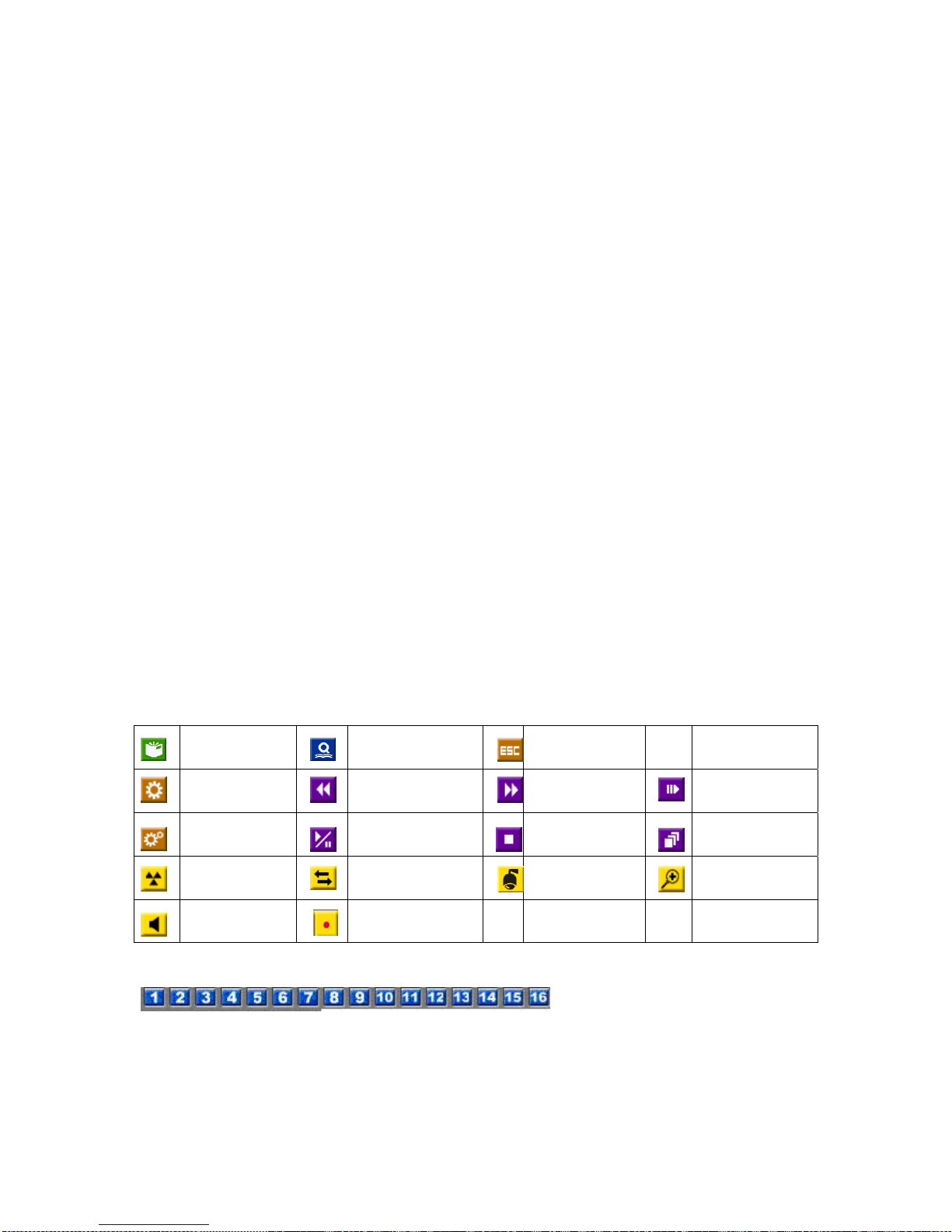
74
Appendix B--The mouse operation interface reference
When you use the mouse operations of the DVR pl ease move the cursor to screen bottom, you
will see the icons of mouse function displayed, and press the diagram mark to choose an
operation you need.. Under Control mode in the PTZ, please pick out to install channel of camera,
put the mouse and move the direction, press left key of mouse and can immediately turn to move,
The diagram object function and the front panel key or the remote control key function are basic
and similar, The function shows as follows:
Menu Search Escape Sequence
Fold tools Fast backward Fast forward Step forward
Unfold tools Play/Pause Stop Copy
Alarm reset Live/Playback PTZ Zoom
Volume Record
- split windows display selection
- channel no. selection for allocation
and display
Page 76
75
B-1 Motion detection setup
Move the cursor to Menu -> Setup -> Camera -> Motion setting -> Detection
setting
Move the cursor to screen below, the icons of motion detection will be displayed.
Set/Reset
highlighted area
Set/Reset
whole area
Sensitivity Test
B-2 PTZ setup and control
Set up the PTZ in RS485 first: Menu-> setup ->RS-485
Move cursor to focused camera, then to screen bottom, and click the , the functions are
as follows:
Page 77
76
Go to Figure down Zoom Figure up
Preset
position
Focus Auto Focus Iris
SEQ Auto pan Speed Mark
B-3 Video adjustment icons
This camera default All camera default Default
B-4 Common icons
For each set up field/submenu, you may find these icons for operation:
Up Down Enter Code
Switch
Left Right Escape Options
selection
Confirmed Space Mark(Symbol
s)
Close
Window
Page up Page down forward Back space
B-5 Keyboard input
While in text input field, you may click the mouse left key, it would appear following keyboard
input icons for alpha-numeric characters input:
Page 78

77
Click the
, it will appear the following symbol table for selection:
Text input
Digital input
“123”/”abc”/”AB
C” input switch
Page 79

78
Appendix C – Specifications
O.S. Embedded Linux 2.6
Multiplex
Sixfold operation - simultaneous record, live,
playback, backup, control, & remote access
System
Certification FCC, CE, LVDS, etc.
Format NTSC/EIA or PAL/CCIR
Input 16/9-CH, BNC, 1Vp-p/75ohm
Main monitor
BNC x 1, 1Vp-p/75ohm
VGA D-SUB 15-pin connector
Main-AUX BNC x 2 (Inpu t x 1, Output x 1 ), 1Vp-p/75ohm
Call monitor BNC x 1, 1Vp-p/75ohm
Call-AUX BNC x 2 (Input x 1, Output x 1), 1Vp-p/75ohm
Loop-through 16/9-CH as Video Input, BNC, 1Vp-p/75ohm
Loss detection Yes
Video
Motion detection Yes, with configurable detection area & sensitivity
Input
2 Stereo Audio - 4 RCA-jack connectors, line-in level
(100mV-2Vrms)
Audio
Output
2 Audio – 2 RCA-jack connectors, line-out level (up
to 2Vrms)
Compression
Video: H.264
Audio: ADPCM
Frame rate (IPS)
& Resolution
NTSC – 60 / 720*480, 120 / 720*240, 240 / 360*240
PAL – 50 / 720*576, 100 / 720*288, 200 / 360*288
Mode Manual/Schedule/Alarm/Motion
Pre-record time 0 – 60 seconds
Record
Post-record time 0 - 60 minutes
Resolution NTSC – 720*480, PAL – 720*576
Split windows 1/4//7/9/10/13/16
Frame rate Up to 30 (NTSC) / 25 (PAL) IPS per display window
Freeze Yes
Sequential switch User adjustable
Display
Digital Zoom X2, X4
Frame rate (IPS)
& Resolution
NTSC – 30 / 720*480, 60 / 720*240, 120 / 360*240
PAL – 25 / 720*576, 50 / 720*288, 100 / 360*288
Search Date/time, Camera, Alarm, Motion, & Video Loss
Playback
Operation
Play, Fast Forward, Backward, Pause, Stop, etc.
Remote I.E. and HEM can also Print, Snapshot
HDD
Up to 4 sets of 3.5” IDE/SATA type HDDs, up to
1TB(1000GB) storage size for each HDD
Partitions
Configurable alarm partition size
Configurable auto-overwrite or not
Storage
Backup
2 USB 2.0 ports for USB 2.0 disk drives, DVD+RW,
DVD+R, DVD-R
, card readers, HDD, etc.
Internal DVD models: DVD+RW, DVD+R, DVD-R
Alarm Input 16 contact or TTL/CMOS signal, polarity selectable
Page 80

79
Output 2 Normally Open, 2 Normally Closed relay output
Buzzer Yes
Triggered by Sensor input, Video loss, & Motion
Event log Yes
Ethernet 1 RJ-45 10/100BaseT Et hernet connector
Web Remote setup, monitoring, backup, alarm notification,
1 I.E. for up to 4 DVRs
E-mail Alarm notification to stationary or mobile devices
Video 1/4/9/16 split-window & SEQ mode for I.E. and HEM
Dynamic electronics maps for HEM
Audio Bidirectional
Protocol TCP/IP, HTTP, PPPoE, DHCP, DDNS, TSP
Remote users Up to 5 users simultaneously
Bandwidth TCP/IP type dynamic sliding window control
Network
Remote stations PC
I/R 1 I/R remote controller to control up to 4 DVRs
Mouse port For mouse to control OSD with GUI operations
RS-232 1 D-type female connector for PTZ
Control
RS-485 / RS-422 1 RJ-45 connector for PTZ control
Local On screen setup via keypad, I/R remote controller,
and/or RS-485 keyboard controller
Remote Setup & upload via Windows application software
Setup
Multi-lingual Yes
System recovery Auto power on after power loss recovery
Timer Built-in real time clock
Reliability
Security Multi-level password (3 levels, up to 18 accounts)
protection with authentication key for remote access
Weights &
Measures
Dimension
Weight
430(W) x 330(D) x 88(H)mm
5.0 KG (without HDD)
Source 90~264 VAC, 47~63 Hz
Power
Consumption 110W Max.
Operating Tem perature 0oC ~ +45oC
Page 81

80
Appendix D – Time Zone Table
Time Zone Offset DST Start End
Samoa GMT – 11:00
Hawaii GMT – 10:00
Alaska GMT – 09:00
ˇ
Mar, 2nd Sun, 2:00 Nov, 1st Sun, 2:00
Pacific Time (US & Canada) GMT – 08:00
ˇ
Mar, 2nd Sun, 2:00 Nov, 1st Sun, 2:00
Arizona, US Mountain GMT – 07:00
Chihuahua, La Paz, Mazatlan GMT – 07:00
ˇ
May, 1st Sun, 2:00 Sep, last Sun, 2:00
Mountain Time (US & Canada) GMT – 07:00
ˇ
Mar, 2nd Sun, 2:00 Nov, 1st Sun, 2:00
Central America, Saskatchewan GMT – 06:00
Central Time (US & Canada) GMT – 06:00
ˇ
Mar, 2nd Sun, 2:00 Nov, 1st Sun, 2:00
Guadalajara, Mexico City,
Monterrey
GMT – 06:00
ˇ
May, 1st Sun, 2:00 Sep, last Sun, 2:00
Bogota, Lima, Quito, Indiana
(East)
GMT – 05:00
Eastern Time (US & Canada) GMT – 05:00
ˇ
Mar, 2nd Sun, 2:00 Nov, 1st Sun, 2:00
Atlantic Time (Canada) GMT – 04:00
ˇ
Mar, 2nd Sun, 2:00 Nov, 1st Sun, 2:00
Caracas, La Paz GMT – 04:00
Santiago GMT – 04:00
ˇ
Oct, 2nd Sun, 0: 00 Mar, 2nd Sun, 0:00
Newfoundland GMT – 03:30
ˇ
Apr, 1st Sun, 2:00 Oct, last Sun, 2:00
Brasilia GMT – 03:00
ˇ
Oct, 3rd Sun, 2:00 Feb, 3rd Sun, 2:00
Buenos Aires, Georgetown GMT – 03:00
ˇ
Oct, 3rd Sun, 2:00 Feb, 2nd Sun, 2:00
Greenland GMT – 03:00
ˇ
Mar, last Sun, 1:00 Oct, last Sun, 1:00
Mid-Atlantic GMT – 02:00
ˇ
Mar, last Sun, 2:00 Sep, last Sun, 2:00
Azores GMT – 01:00
ˇ
Mar, last Sun, 2:00 Oct, last Sun, 3:00
Cape Verde GMT – 01:00
Casablanca, Monrovia GMT + 00:00
Dublin, London GMT + 00:00
ˇ
Mar, last Sun, 1:00 Oct, last Sun, 2:00
Western Europe, Central Europe GMT + 01:00
ˇ
Mar, last Sun, 2:00 Oct, last Sun, 3:00
West Central Africa GMT + 01:00
Eastern Europe GMT + 02:00
ˇ
Mar, last Sun, 0:00 Oct, last Sun, 1:00
Cairo GMT + 02:00
ˇ
Apr, last Fri, 2:00 Sep, last Fri, 2:00
Harare, Pretoria GMT + 02:00
Helsinki, Kyiv, Riga, Sofia,
Tallinn
GMT + 02:00
ˇ
Mar, last Sun, 2:00 Oct, last Sun, 3:00
Jerusalem GMT + 02:00
ˇ
Apr 1, 2:00 Oct, 2nd Sun, 2:00
Baghdad GMT + 03:00
ˇ
Apr 1, 3:00 Oct 1, 4:00
Kuwait, Riyadh, Nairobi GMT + 03:00
Moscow, St. Petersburg,
Volgog ra d
GMT + 03:00
ˇ
Mar, last Sun, 2:00 Oct, last Sun, 3:00
Tehran GMT + 03:30
ˇ
Mar, 4th Tue, 2:00 Sep, 4th Thu, 2:00
Abu Dhabi, Muscat GMT + 04:00
Page 82

81
Baku, Tbilisi, Yerevan GMT + 04:00
ˇ
Mar, last Sun, 2:00 Oct, last Sun, 3:00
Time Zone Offset DST Start End
Kabul GMT + 04:30
Ekaterinburg GMT + 05:00
ˇ
Mar, last Sun, 2:00 Oct, last Sun, 3:00
Islamabad, Karachi, Tashkent GMT + 05:00
Chennai, Mumbai, New Delhi GMT + 05:30
Kathmandu GMT + 05:45
Almaty, Novosibirsk GMT + 06:00
ˇ
Mar, last Sun, 2:00 Oct, last Sun, 3:00
Astana, Dhaka, Sri Lanka GMT + 06:00
Rangoon GMT + 06:30
Bangkok, Hanoi, Jakarta GMT + 07:00
Krasnoyarsk GMT + 07:00
ˇ
Mar, last Sun, 2:00 Oct, last Sun, 3:00
Irkutsk, Ulaan Bataar GMT + 08:00
ˇ
Mar, last Sun, 2:00 Oct, last Sun, 3:00
Beijing, Chingqing, H. K.,
Urumqi
GMT + 08:00
Kuala Lumpur, Perth, Singapore GMT + 08:00
Taipei GMT + 08:00
Osaka, Seoul, Tokyo GMT + 09:00
Yakutsk GMT + 09:00
ˇ
Mar, last Sun, 2:00 Oct, last Sun, 3:00
Adelaide GMT + 09:30
ˇ
Oct, last Sun, 2:00 Mar, last Sun, 3:00
Darwin GMT + 09:30
Brisbane, Guam, Port Moresby GMT + 10:00
Canberra, Melbourne, Sydney GMT + 10:00
ˇ
Oct, last Sun, 2:00 Mar, last Sun, 3:00
Hobart GMT + 10:00
ˇ
Oct, 1st Sun, 2:00 Mar, last Sun, 3:00
Vladivostok GMT + 10:00
ˇ
Mar, last Sun, 2:00 Oct, last Sun, 3:00
Magadan, Solomon Is. GMT + 11:00
Auckland, Wellington GMT + 12:00
ˇ
Oct, 1st Sun, 2:00 Mar, 3rd Sun, 2:00
Fiji GMT + 12:00
Kamchatka GMT + 12:00
ˇ
Mar, last Sun, 2:00 Oct, last Sun, 3:00
Anadyr GMT + 13:00
ˇ
Mar, last Sun, 2:00 Oct, last Sun, 3:00
Nuku’alofa GMT + 13:00
Page 83

82
Appendix E – Recording Table
NTSC Recording Time (in Hour) - For Reference Only
System Storage (GB): 200
Average Recording Rate (IPS)
Resolution Quality
Picture Size (KB)* 240 120 60 30 15 10 5
720x480
9 27.7
31 67 134 201 401
(Full D1)
8 24.5 33 76 151 227 454
7 21.0
41 88 176 265 529
6 18.4 52 101 201 302 604
5 14.0
61 132 265 397 794
4 11.3 75 164 328 492 983
3 7.7 111 241 481 722 1443
2 5.6 146 331 661 992 1984
1 3.6 231 514 1029 1543 3086
720x240
9 13.9 31 67 133 266 400 799
(Half D1)
8 12.3
33 75 151 301 452 903
7 10.5 41 88 176 353 529 1058
6 9.2
52 101 201 403 604 1208
5 7.0 61 132 265 529 794 1587
4 5.7
75 162 325 650 975 1949
3 3.9 111 237 475 950 1425 2849
2 2.8
146 331 661 1323 1984 3968
1 1.8 231 514 1029 2058 3086 6173
360x240
9 7.0
31 67 133 266 529 794 1587
(CIF)
8 6.2 33 75 149 299 597 896 1792
7 5.2
41 88 176 353 712 1068 2137
6 4.6 52 101 201 403 805 1208 2415
5 3.5
61 132 265 529 1058 1587 3175
4 2.9 75 162 325 650 1277 1916 3831
3 2.0
111 237 475 950 1852 2778 5556
2 1.4 146 331 661 1323 2646 3968 7937
1 0.9
231 514 1029 2058 4115 6173 12346
* Average Picture Size is estimated based on typical camera scene, and averaged by H.264 I/P/P
frames.
Page 84

83
PAL Recording Time (in Hour) - For Reference Only
System Storage (GB): 200
Average Recording Rate (IPS)
Resolution Quality
Picture Size (KB)* 200 100 50 25 12.5 8 4
720x576
9 36.0
31 62 123 193 386
(Full D1)
8 32.0 33 69 139 217 434
7 27.3
41 81 163 254 509
6 21.3 52 104 209 326 652
5 18.3 61 121 243 379 759
4 14.7 75 151 302 472 945
3 10.0 111 222 444 694 1389
2 7.3
146 304 609 951 1903
1 4.7 231 473 946 1478 2955
720x288
9 18.0 31 62 123 247 386 772
(Half D1)
8 16.0
33 69 139 278 434 868
7 13.6 41 82 163 327 511 1021
6 10.7
52 104 208 415 649 1298
5 9.2 61 121 242 483 755 1510
4 7.4
75 150 300 601 938 1877
3 5.0 111 222 444 889 1389 2778
2 3.7 146 300 601 1201 1877 3754
1 2.4 231 463 926 1852 2894 5787
360x288
9 9.0
31 62 123 247 494 772 1543
(CIF)
8 8.0 33 69 139 278 556 868 1736
7 7.2
41 82 163 327 654 1021 2042
6 5.7 52 103 206 412 823 1286 2572
5 5.0
61 121 242 483 966 1510 3019
4 4.0 75 150 300 601 1201 1877 3754
3 2.8
111 222 444 889 1778 2778 5556
2 2.2 146 292 585 1170 2339 3655 7310
1 1.4
231 463 926 1852 3704 5787 11574
* Average Picture Size is estimated based on typical camera scene, and averaged by H.264 I/P/P
frames.
NOTE:Above say a reference only, if any difference, please take actual machine as quasi-
Page 85
84
Appendix F– Compatible HDD List
The other HDDs, please test by yourselves. For 4ch DVR suggest Max 500G HDD only.
Item
Serial No. Size(GB) Drive
WD WD5000AVJS-63YJAO 500 IDE
WD WD3200JB (CARIAR-SE) 320 IDE
WD WD2000JB-00GVC0 200 IDE
WD WD1600AAJB-00WRA0 160 IDE
WD WD2000JB-00KFA0 200 IDE
WD WD2500JB-00REA0 250 IDE
WD WD5000AACS-WD Caviar GP 500 SATA
WD WD5000AAKS-WD Caviar SE16 500 SATA
WD WD7500AACS-WD Caviar GP 750 SATA
WD WD10EACS-WD Caviar GP 1000 SATA
WD WD1600AAJS-22PSA0, CARIAR SE 160 SATA
HITACHI 0A34079 MAR-2007 160 IDE
HITACHI HDT722516DLAT80 160 IDE
HITACHI HDT722525DLAT80 250 IDE
HITACHI HDS728080PLAT20 80 IDE
HITACHI 0A36523- MAR-2008 500 SATA
HITACHI 0A35155 - MAR-2008 1000 SATA
Maxtor 6L080P0 80 SATA
Maxtor STM3500320AS-DiamondMax 22 320 SATA
Maxtor STM31000340AS-DiamondMax 22 1000 SATA
Maxtor 6V160E0 -DiamondMax 10 160 SATA
Seagate ST3320820A-Barracuda 7200.10 320 IDE
Seagate ST3500630A-Barracuda 7200.10 500 IDE
Seagate ST3200827AS, Barracuda 7200.9 200 IDE
Seagate ST3160815A, Barracuda 7200.10 160 IDE
Seagate ST3160815AV, SV35.2 160 IDE
Seagate ST380215A, Barracuda 7200.10 80 IDE
Seagate ST3160812A, Barracuda 7200.9 160 IDE
Seagate ST3160815AS, Barracuda 7200.10 160 SATA
Seagate ST3500320AS, Barracuda 7200.11 500 SATA
Page 86
85
Seagate ST37500330AS, Barracuda 7200.11 750 SATA
Seagate ST380815AS, Barracuda 7200.10 80 SATA
Seagate ST3500320AS Barracuda 7200.11 500 SATA
Seagate ST31000340AS-Barracuda 7200.11 1000 SATA
SAMSUNG HA200JC 200 IDE
 Loading...