

Page 1
*23762*
Control Box
23762
Models 7902 SEQ & ES7902 SEQ
L For closer information see closer installation instruction sheet
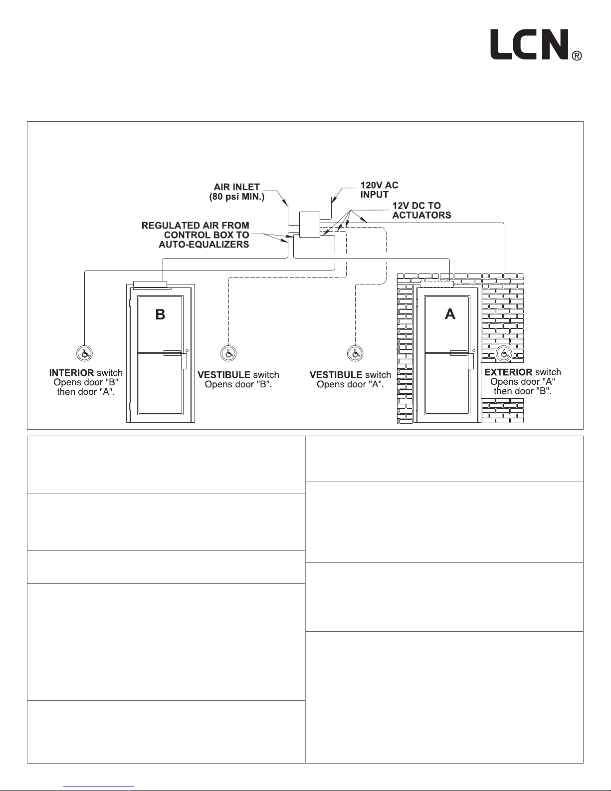
Typical Electric & Air Supply Hook Up
Installation Instructions
1 Locate box on interior of building within 100 tubing feet
of the door to be controlled. Box must be in a clean,
dry, well ventilated place where temperatures do
not exceed 120°F or fall below 35°F.
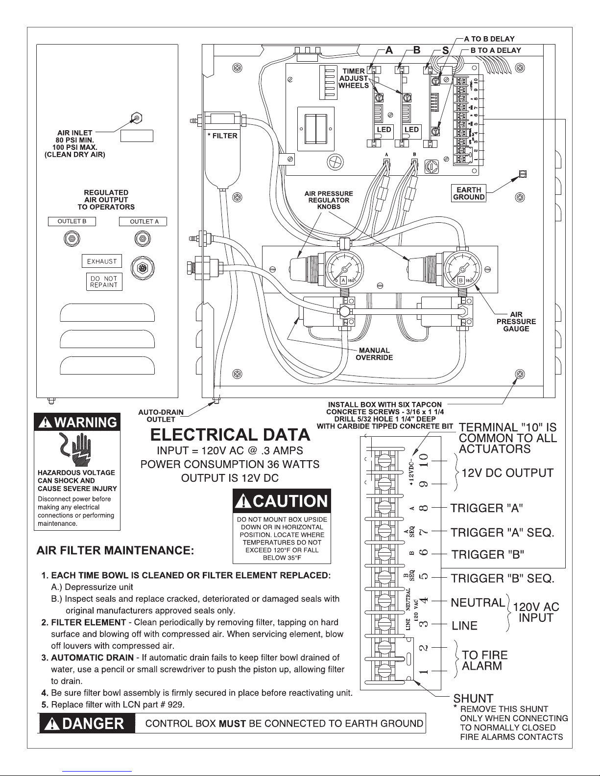
2 Mount box to a structurally sound surface using
screws provided as shown on page 2 with air ttings
on left side as shown. Do not mount box upside
down or on a horizontal plane.
3 Refer to instructions packed with actuators and
connect leads to terminals 5 through 10 as required.
4 Connect unpowered 120V AC input to terminals 3,
4, and ground screw. (Line side to ternimal 3, neutral
side to terminal 4 and ground wire to ground screw).
If door control is on a re door, 120V AC input must
be interrupted by the re alarm panel when in alarm.
When dry auxiliary re alarm contacts are used,
remove shunt from terminals 1 and 2 and connect to
dry contacts of re detector or alarm panel. Terminals
1 and 2 are in series with line side of 120V input.
5 Turn on power. Air valve will operate one cycle when
power is applied.
6 Air pressure output valve has been preset at factory.
If more air pressure is required to adequately open
doors, adjust regulator valves found inside control box.
7 Adjust time delay to keep air valve energized by
turning adjustment wheel on timer modules “A” & “B”
(CW to increase - CCW to decrease). The LED (light)
on the timer module indicates the valve is energized.
The time can be adjusted from 0-30 seconds. 10
seconds is a “normal” delay.
8 When using sequential operation, adjust dual timer
module “S” for desired delay between door operation.
(CW to increase delay; CCW to decrease delay). Top
timer delays “A” to “B” operation; the bottom timer
delays “B” to “A” operation.
9 Test actuators to ensure wiring and tubing are properly
connected.
1
Page 2
A
2
Page 3
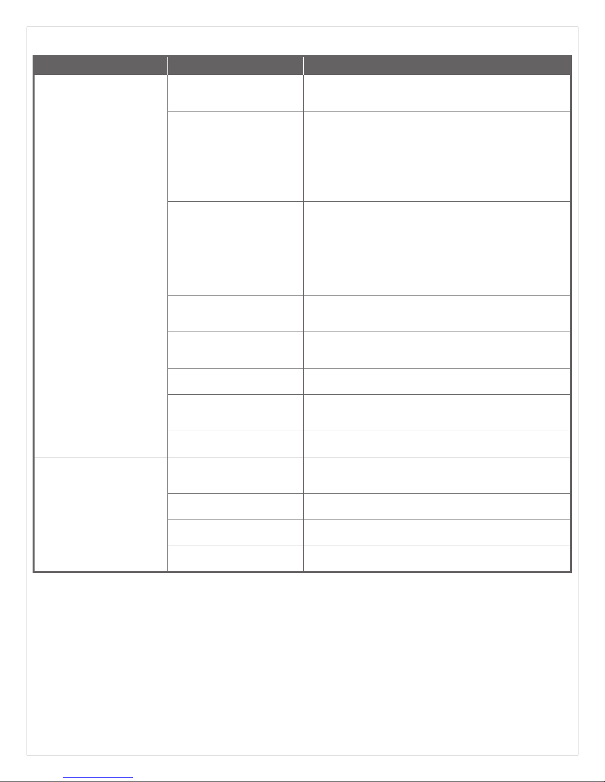
Installation Troubleshooting Chart
Symptom Possible Cause Suggested Remedy
No Power Opening. No power to control box/blown
fuse.
Actuator(s) not connected
properly.
Fire alarm system causing open
circuit on terminals 1 & 2.
No input to Auto-Equalizer
operator.
Air lines obstructed with dirt or
ice.
Air valves not working. Make sure air valve leads are plugged into main board. (Be sure
Low or no air inlet pressure to
control box.
No air output to Auto-Equalizer
operator.
Power opening will not time
out.
Scanner maintaining signal to
control box.
Switch circuit maintaining
contact.
Air valve blocked open with
contaminant.
Control box exhaust restricted. Exhaust mufer may be clogged. Clean in alchohol or mineral
Verify 120VAC 60HZ power is present at terminals 3 & 4 on
control box terminal strip. Check fuse. Replace only with 5 amp
(3AG type) fuse.
Be sure a timer module board is rmly in place in “A,” “B” & “S”
slots. Operate actuator(s). LED on timer module should light
when actuator is used. If not, briey short actuator terminal in
the control box. If LED lights, check wiring to actuators for an
open circuit. If it does not light, check for voltage at terminals 9
&10. Voltage should read from 11.75 to 13.25V DC. If there is no
reading, disconnect leads from terminals 9 & 10. Short actuator
terminals. If LED lights, check for short circuit in actuators.
Shunt terminals 1 & 2 with power off. Restore power. If control
operates when actuator terminals in the control box are shorted,
an open circuit exist in wiring to re alarm. When Auto-Equalizer
is not used with re alarms, terminals 1 & 2 must be permanently
shorted with a shunt.
IMPORTANT! When Auto-Equalizer is connected to re alarm,
make sure shunt is removed from terminals 1 & 2. Terminals 1 &
2 are one leg of 120V line.
Disconnect tubing from Auto-Equalizer operator. Try actuator and
verify that air is coming out of tubing. If not, trace tubing to control
box, checking for breaks or kinks in air line.
Clean or thaw lines and reroute if necessary. Eliminate dips near
cold zones. If freezing is a repeated problem, desiccant lter may
need to be changed.
valves in system are plugged into connectors “A” & “B”.)
Check compressor output to make sure air shut-off is open. 80
psi must be available at the control box. If not, check compressor
and lines.
Check pressure gauge in control box. Adjust as required, if
necessary. Check for leaking or damaged lines in control box.
Make sure lenses are clean and there are no obstructions in front
of scanner. Model 909 or 939 proximity scanner may “see” an
opposite wall. Adjust range as described earlier.
Check for short circuit or error in wiring to actuator.
Cycle valve several times by momentarily shorting actuator
terminals. This should clear valve.
spirits.
3
Page 4
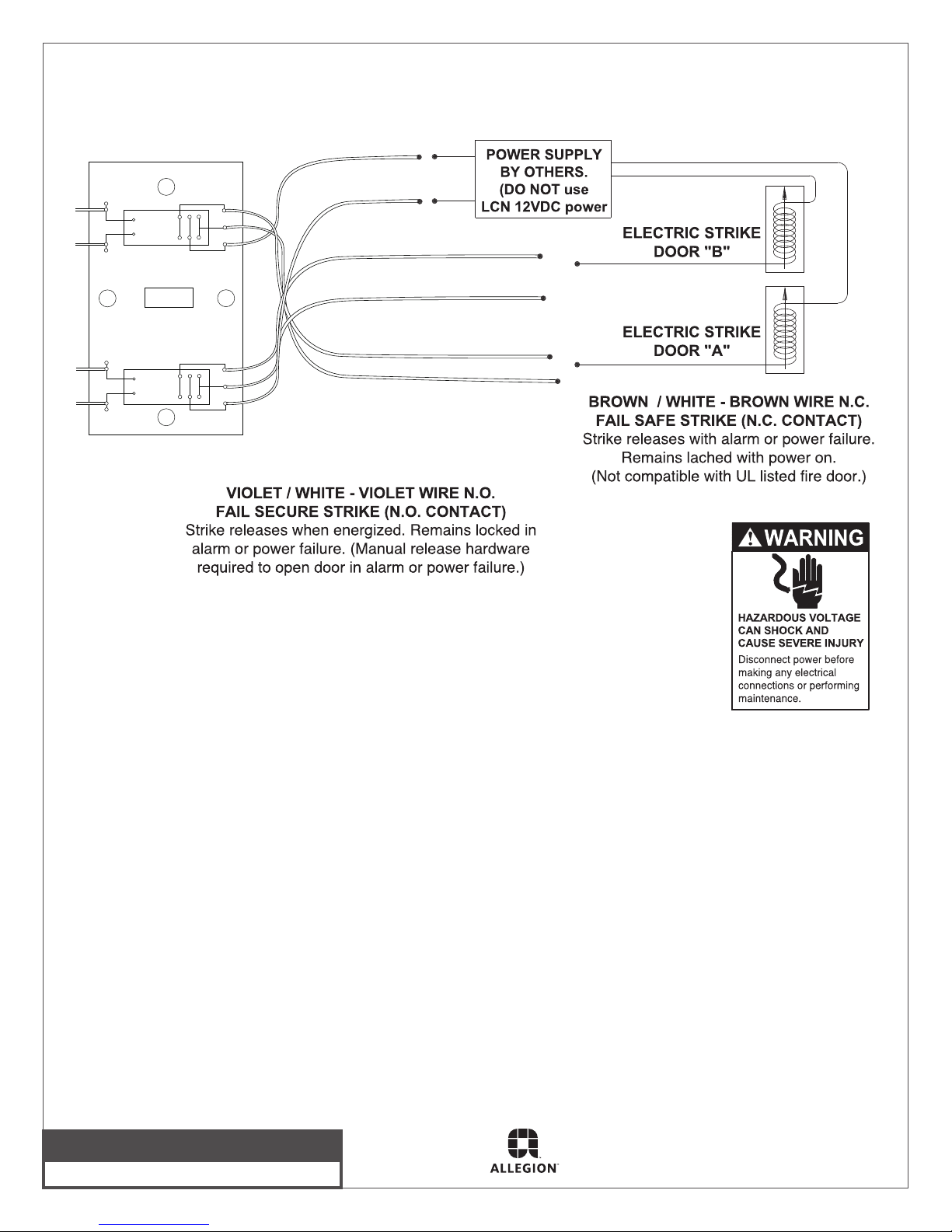
Model ES7902 SEQ. for use with Electric Latching Hardware
ES7902 SEQ. - 2 electric strikes maximum
PINK
BLK
BLK
K1
BRN
VIO
PINK
WHITE - RED
WHITE - BROWN (N.C.)
WHITE - VIOLET (N.O.)
BLK
BLK
K2
WBRN
WVIO
WRED
BROWN (N.C.)
VIOLET (N.O.)
Customer Service
1-877-671-7011 www.allegion.com/us
© Allegion 2014
Printed in U.S.A.
23762 Rev. 05/14-e
4
 Loading...