

LCI Solera Destination Installation And Owner's Manual
®
Solera
Destination Awning
Installation and Owner’s Manual
(For Aftermarket Application)
Solera®
Destination
Awning
Installation and
Owner’s Manual
(For Aftermarket Applications)
Table of Contents
Introduction ..............................................2
Quick Facts ..............................................2
Preparation ...............................................2
Resources Required .....................................2
Installation ................................................3
Installing the Awning Rail (If Necessary) ................3
Assembling the Awning ..................................4
Mounting the Bottom Mounting Brackets ................4
Mounting the Awning ....................................5
Securing the Fabric ......................................6
Installing the Stop Bolt ...................................7
Operation .................................................7
Extending the Awning ...................................7
Retracting the Awning ...................................7
Fabric Replacement ......................................8
Fabric Removal ..........................................8
Installing Replacement Fabric ...........................9
Classic Awnings Fabric Replacement Turn Chart .......9
lci1.com 574-537-8900 Rev: 03.09.18
Maintenance - Solera
Fabric Care ............................................ 10
Solera
Awnbrella™ Parts List .................................. 12
Resources Required ................................... 13
Installation .............................................. 13
Ground Support Introduction ......................... 18
Resources Required ����������������������������������� 18
Installation .............................................. 18
Removal of Ground Support .......................... 20
1
®
Destination Awning Troubleshooting ........ 11
Spacing Awnbrella Arms ���������������������������� 13
Drilling the Roller Tube ................................ 14
Mounting Hanger Blocks .............................. 15
Inserting Awnbrella Arms .............................. 15
Velcro® Stabilizers ..................................... 16
Proper Awning Extention for Awnbrella Arms ......... 17
Special Notes: ......................................... 17
CCD-0001255
®
Awnings ....................... 10
®
Solera
Destination Awning
Installation and Owner’s Manual
(For Aftermarket Application)
Introduction
Destination campers (or seasonal campers) who set up
camp for extended stays will love the Solera® Destination
Awning because it provides an additional 20 percent more
shaded outdoor area. Not only does the Solera Destination
Awning provide a 9'8" projection canopy, it also comes
with a Solera® Awning Ground Support and the Solera®
Awnbrella® to keep the fabric arched and taut to minimize
wind ap and enable rain runoff.
Quick Facts
• Operates like any manual spring roll up awning - basically
it’s a jlarger version of the Solera Classic Awning
• Wide selection of vinyl fabric and acrylic fabrics
• Comes standard with the Solera Awnbrella awning bows
which hold fabric tight and arched so water doesn’t pool
and debris can easily runoff
• Comes with a Solera Ground Support for added
stabilization
• Custom hardware color options available
Additional information about this product can be obtained
from www.lci1.com/support or by downloading the free
MyLCI app. The app is available on iTunes® for iPhone®
and iPad® and also on Google Play™ for Android™ users.
iTune s®, iPhone® and iPad® are registered trademarks of
Apple Inc. Google Play™ and Android™ are trademarks of
Google Inc.
FAILURE TO FOLLOW THE INSTRUCTIONS PROVIDED
IN THIS MANUAL MAY RESULT IN DEATH, SERIOUS
INJURY, COACH DAMAGE, OR VOIDING OF THE
COMPONENT WARRANTY�
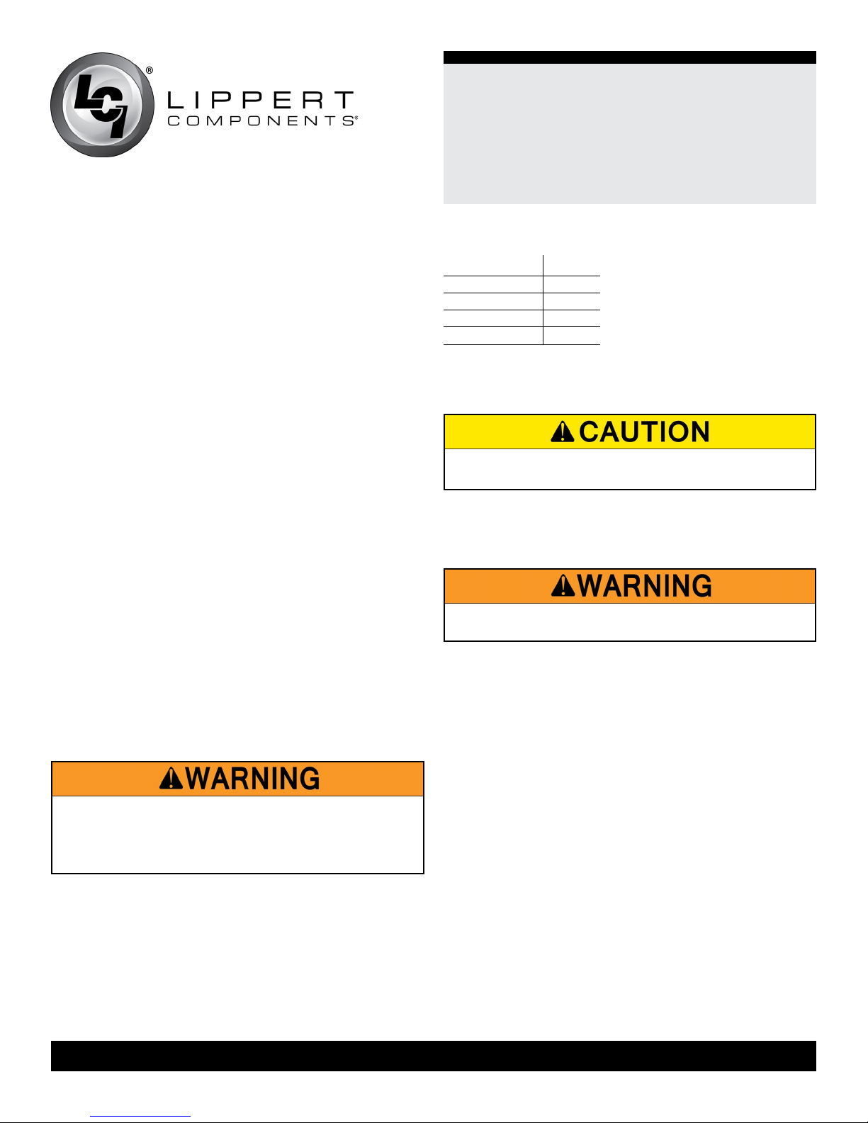
NOTE: Solera Destination Awning drive and idler heads
are preloaded with tension and secured with cotter pins
from the factory. If the cotter pins have been removed
or otherwise lost, and tension needs to be added to the
heads, use the turn chart (Fig.1) to add the correct number
of turns to the awning heads.
Classic Awnings Pre-Install Turn Chart
Size Turns
6' to 10'
11' to 14'
15' to 18'
19' and up
Fig.1
4
5
6
8
Preparation
MOVING PARTS CAN PINCH, CRUSH OR CUT� KEEP
CLEAR AND USE CAUTION�
Do NOT remove the following items until instructed:
1� Tape securing the fabric.
2� Cotter pins in the spring assemblies.
REMOVING THESE ITEMS PREMATURELY MAY CAUSE
SERIOUS INJURY OR PROPERTY DAMAGE�
Resources Required
• 1 to 3 People
• Cordless or Electric Drill or Screw Gun
• Appropriate Drive Bits, including ⁄" and ½"
• Screwdriver
• Ratchet
• ⁄" Socket
• ½" Socket
• ½" Wrench
• ⁄" Drill Bit
• Non-Permanent Method of Marking
• Silicone Sealant or Butyl Tape
• Silicone Lubricant
lci1.com 574-537-8900 Rev: 03.09.18
2
CCD-0001255
®
Solera
Destination Awning
Installation and Owner’s Manual
(For Aftermarket Application)
Installation
NOTE: All fasteners supporting the awning assembly MUST have a backer within the structure of the wall of the unit.
Refer to unit manufacturer for proper location.
Installing the Awning Rail (If Necessary)
NOTE: Awning rail not included.
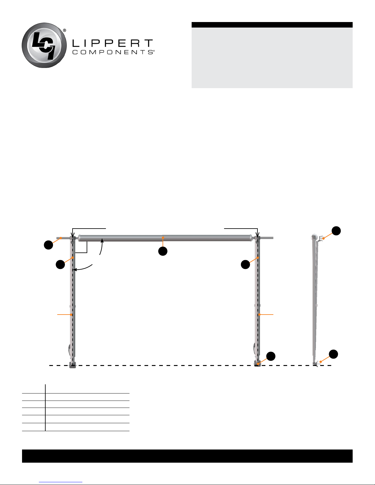
1� Position the awning rail along the line where roof and wall meet.
NOTE: The awning rail MUST be level and parallel with the oor line of the unit (Fig.2).
2� After determining the awning rail’s proper location, mark its position with a non-permanent method of marking.
3� Seal the back of the awning rail.
4� Align the awning rail on the wall and secure with #10 x ¾" screws, using all fastener holes.
Assembling the Awning
NOTE: The head assemblies (Fig.3A) and support arm assemblies (Fig.3B) are numbered to ensure proper assembly.
Match the proper support arm assembly to the correct head assembly.
A
B
Dotted line
= vertical
centerline
Fig.2
Letter Description
A Awning Rail
B Support Arm Assembly
C Roll Tube Assembly
D Lower Mounting Bracket
E Upper Mounting Bracket
Awning Width = Head Bolt to Head Bolt
C
90°
Front Facing View
Floor Line
Side View
E
B
Dotted line
= Vertical
centerline
D
D
lci1.com 574-537-8900 Rev: 03.09.18
3
CCD-0001255
®
Solera
Destination Awning
Installation and Owner’s Manual
(For Aftermarket Application)
1� On a at surface, carefully lay out the support arm
assemblies and roll tube assembly. The cam lock MUST
be on the right side of the roll tube when facing the unit.
NOTE: Take care not to set the awning on any surface that
may damage the assembly or fabric.
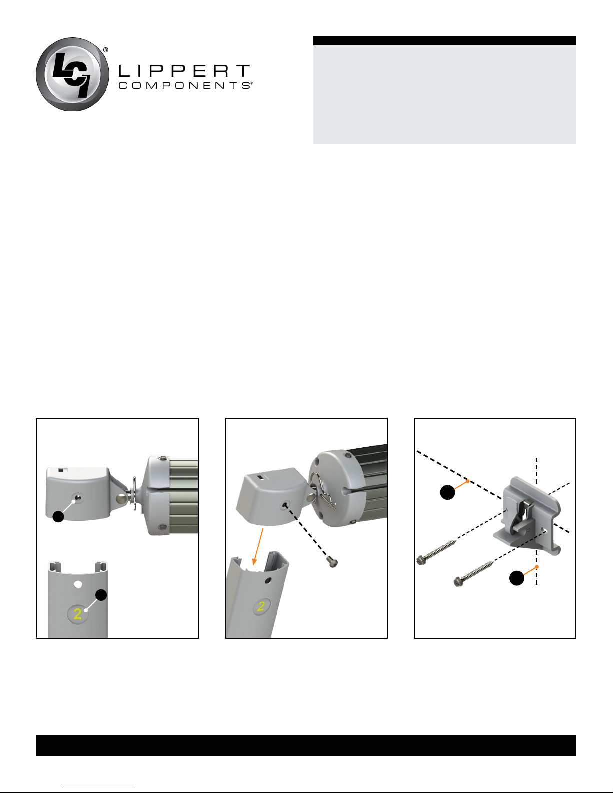
2� Slide the left support arm assembly into the idler head
assembly of the roll tube. Align the holes and secure using
one (1) ¼-20 x ½" Phillips drive screw (Fig.4).
3� Repeat step 2 for the right support arm assembly.
4� Measure and conrm the width of the awning. The
distance is measured from head bolt to head bolt (Fig.2).
Mounting the Bottom Mounting Brackets
1� On the awning rail, mark the position of the support arm
assemblies using the head bolt to head bolt measurement.
Ensure that the support arm assemblies will not interfere with
any lights, vents or the operation of any windows or doors.
2� Using a non-permanent method of marking, mark a
perpendicular line from the mark on the awning rail down
to the oor line. This is the centerline of the support arm
assembly (Fig.2). Do this for both support arm assemblies.
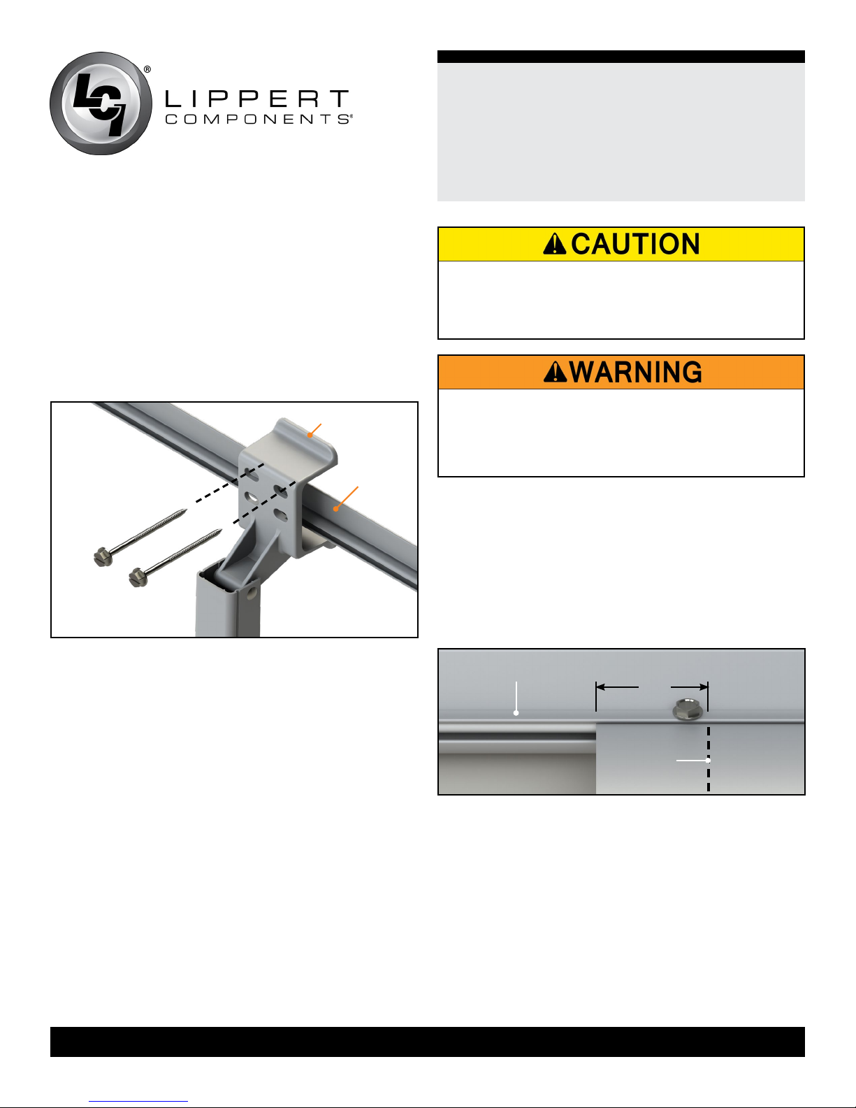
3� Position the bottom bracket with the fastening points at the
oor line (Fig.5A) and center the bracket on the centerline mark
of the support arm assembly (Fig.5B). Mark the hole locations.
Using a ⁄" drill bit, pre-drill both holes. Apply a liberal amount
of sealant over the holes and attach the bracket using the ¼" x
2 ½" lag screws provided (Fig.5).
NOTE: All screws supporting the awning assembly MUST
have a backer within the structure of the wall of the unit. Refer
to unit manufacturer for proper location.
4� Repeat step 3 for the other side of the awning.
A
A
B
B
Fig.3 Fig.4 Fig.5
lci1.com 574-537-8900 Rev: 03.09.18
4
CCD-0001255
Mounting the Awning
1� Measure the distance from the awning rail channel to the
lower mounting bracket fastening point.
2� Compare the distance from the center of the roll tube
and the support arm assembly foot to the measurement in
Step 1 and adjust the support arm assembly to make both
distances equal.
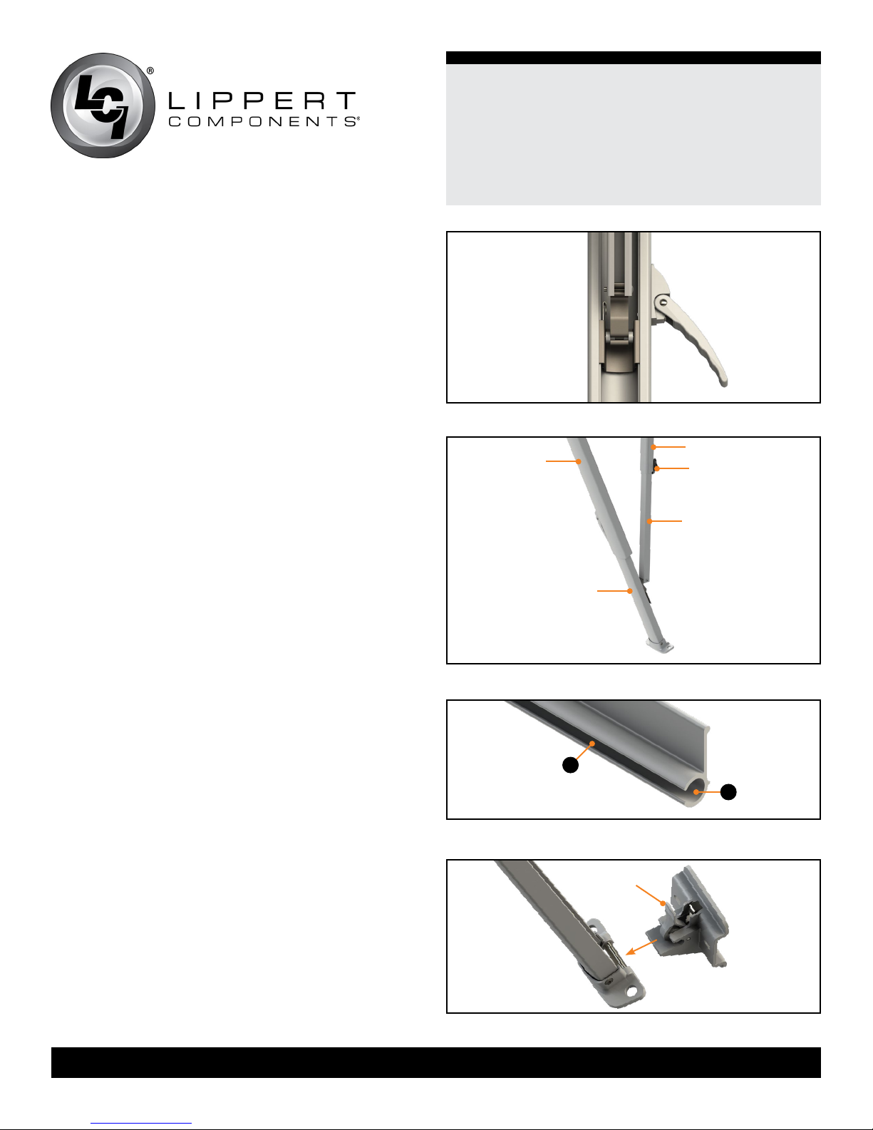
A� Open the support arm assembly handle (Fig.6) and
slide the outer arm lower channel (channel#2) (Fig.7) up
or down to desired height. Close the handle and slide
the outer arm lower channel (channel#2) (Fig.7) until the
locking pin clicks into the nearest positioning hole.
3� Use a screwdriver to spread open either end of the
awning rail on the installation side (Fig.8A).
4� To protect the fabric from damage during installation, le
any sharp edges or burrs from the awning rail channel.
®
Solera
Destination Awning
Installation and Owner’s Manual
(For Aftermarket Application)
Fig.6
channel#3
channel#1
locking knob
channel#4
5� Use silicone lubricant and spray the inside of the awning
rail channel (Fig.8B).
6� Remove the packaging from the fabric. Unroll a small
portion of fabric, but not more than one rotation of fabric.
NOTE: The next step will require three people: One to feed
the polycord into the awning rail channel; two to walk the
support arm assemblies along the awning rail while the
fabric slides into position.
7� Slide the polycord into the awning rail channel and walk
the support arm assemblies and fabric down the awning
rail channel until the support arm assemblies are in line
with the centerline marks made previously.
8� Lift the support arm assembly up and secure the feet
into the previously installed bottom mounting brackets by
pressing the lever and opening the latch (Fig.9).
9� Center the upper mounting brackets on the support
arm assembly centerline marked previously and arrange
the upper mounting brackets to straddle the awning rail.
Tighten the black locking knob on the mount arm upper
channel (channel#3) (Fig.7).
channel#2
Fig.7
B
A
Fig.8
push to open
NOTE: If adjustments need made so the upper mounting
brackets straddle the awning rail, loosen the black locking
lci1.com 574-537-8900 Rev: 03.09.18
5
Fig.9
CCD-0001255
knob on the mount arm upper channel (channel#3) (Fig.7).
Slide the mount arm upper channel (channel#3) (Fig.7)
up or down as needed over the mount arm lower channel
(channel#4) (Fig.7).
10� Once the upper bracket is placed, mark and pre-drill
two ⁄" holes through the awning rail or unit. Apply a
liberal amount of sealant over the holes and attach the
upper mounting bracket using the ¼” x 3" lag screws
provided (Fig.10).
upper mounting
bracket
awning rail
®
Solera
Destination Awning
Installation and Owner’s Manual
(For Aftermarket Application)
FAILURE TO MAINTAIN CONTROL OF THE ROLL
TUBE, FABRIC AND SUPPORT ARM ASSEMBLIES
MAY RESULT IN SERIOUS PERSONAL INJURY OR
PROPERTY DAMAGE�
USE CARE WHEN REMOVING THE COTTER PINS THE
COTTER PINS ARE HOLDING THE PRE-WOUND TENSION
OF THE SPRING� FAILURE TO SECURELY HOLD THE
ROLL TUBE MAY ALLOW THE ROLL TUBE TO RAPIDLY
ROLL UP AND CAUSE PERSONAL INJURY OR DAMAGE�
Securing the Fabric
Fig.10
NOTE: All screws supporting the awning assembly MUST
have a backer within the structure of the wall of the unit.
Refer to the unit manufacturer for proper location. It is
acceptable that the lag screws go through the at portion
of the awning rail.
11� Repeat steps 9-11 for the other support arm assembly.
12� Firmly grasp the roll tube and head and remove the
safety cotter pin from each end of the roll tube. Keeping a
rm grasp on the roll tube and head, place the cam lock in
the roll up position.
13� Allow the fabric to slowly roll up.
1� Roll the awning in and out several times to ensure that
the fabric is square on the roll tube.
2� Secure the fabric in the awning rail no more than 1"
inside the edge of the fabric on both ends using a #6 x
hex head screw. Install the screw down through the awning
rail into the fabric and the polycord (Fig.11).
awning rail
1"
fabric
stitching
Fig.11
½"
lci1.com 574-537-8900 Rev: 03.09.18
6
CCD-0001255
 Loading...