

LCI Power Gear Installation And Service Manual

Slim Rack Slide-out
INSTALLATION AND
SERVICE MANUAL
© Copyright LCI/Power Gear Issued: October 2015 #3010002813, Rev. OG
Controls: 1510000236 and 1510000276
Rev: 05.24.2016
Page 1
3010002813 Slim Rack Slide-out Programming Installation and Service Manual

TABLE OF CONTENTS
System Information 2
Component Descriptions 2
Installation 3
General Requirements 3
Mechanical Components 3
Electrical Components 5
Programming 6
Setting the Retracted Stop Point 6
Setting the Extended Stop Point 6
Installation Issues 6
Operation 7
Prior To Moving the Slide-Out Room: 7
Extending the Room 7
Retracting the Room 7
Preventative Maintenance 7
Troubleshooting 8
Override Mode 9
Manual Emergency Retract Mode 9
Alternate Overrides 10
Notes 13
System Information
The Power Gear Slim Rack Slide-out System is a rack and pinion design operated by a 12 Volt DC gear motor.
Slide-out systems are engineered to provide years of trouble-free service. Changes to weight, stroke, weight
distribution, rail position, controller, power supply, seals, slide toppers, ramps, rollers, etc. all have an effect
on the performance of the system. In order to secure warranty coverage, each new application or changes
to existing applications MUST be audited and approved by Power Gear with a signed document. Audits can
be arranged by contacting your account representative.
Component Descriptions
• Rocker switch that mounts to the wall. It allows room movement and provides end user feedback.
• A specially designed control box that gives the user full control of room movement, in or out. The
control has programmable stops that stop the motor when the room is fully extended or retracted and
the ability to detect faults for ease in troubleshooting.
• Vertical channel with 12V DC gear motor and gear rack arms that mount into the side wall opening and
slide-out room.
• Harnesses to connect the touch pad and motors to the control box.
• Floor rollers (not supplied by Power Gear) that support the room's weight while extending and retracting
the room. Only floor rollers approved by Power Gear can be used with the system. Contact Power Gear
for recommended rollers.
Rev: 05.24.2016
Page 2
Slim Rack Slide-out Manual
Installation
General Requirements
• Power and wiring MUST be such that there is not less than 10.5 running volts supplied at the motor
leads under maximum load.
• Slide system controls MUST come from Power Gear. Controls supplied by other companies will void
warranty.
• Voltage supply MUST come from a 12VDC automotive/RV type battery.
Mechanical Components
1. Install Power Gear-approved floor rollers. Consult roller manufacturer for proper installation
procedures and location.
2. For sealing the screws used to attach end brackets, Power Gear recommends RTV silicone, rubber
gaskets, or closed cell foam gaskets. DO NOT use any type of sealant putty as this can intrude into the
mechanism and possibly cause the system to malfunction.
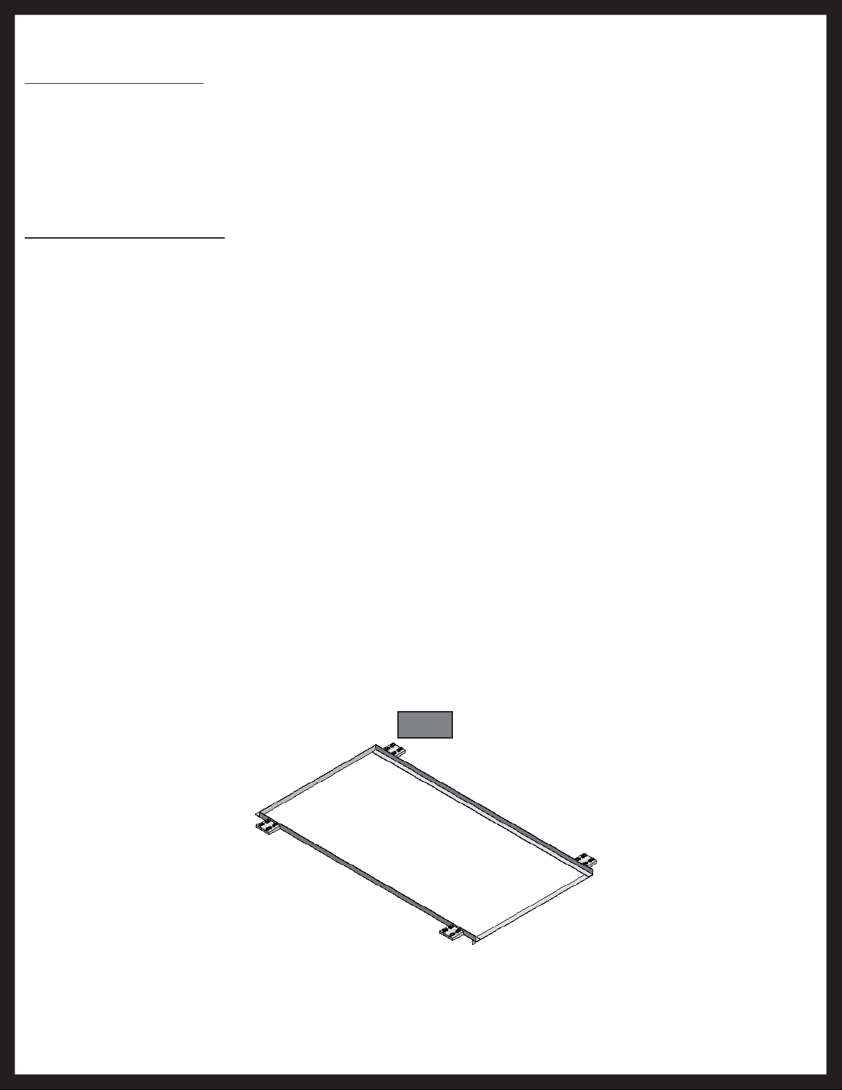
With Drill Fixture
A. A Drill Fixture (Fig. 1) is used to pre-drill the mounting holes for the end brackets and maintain
even spacing between the upper and lower gear rack arms. Even spacing between the gear rack
arms and the location of the end brackets is critical for proper operation of the slide-out. Drill
Fixtures are reusable from system to system. Drill Fixtures are not supplied with the system and
must be purchased from Power Gear to aid in assembly and reduce installation time.
B. Position the Drill Fixture so that the bottom flange of the fixture is pulled up against the bottom of
the room.
C. Move the Drill Fixture out so that it is up flush against the outer room flange.
D. Drill all 16 holes (4 per end bracket) with a #25 drill bit.
E. Place the slide mechanism up to the side of the room and secure end brackets with button or pan
head #10 screws torqued to 40-50 in-lbs.
F. Repeat steps A-E for the other side of the slide-out room. Proceed to step #3.
Rev: 05.24.2016
Fig. 1
Page 3
Slim Rack Slide-out Manual
3. Lift the slide room box into the coach opening and push in until the mounting flange meets the
exterior wall.
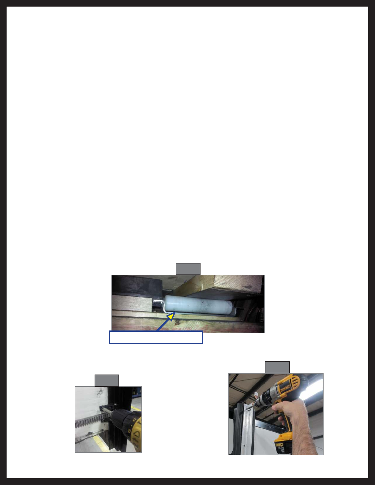
4. Verify the weight of the room is supported by the floor rollers and not the slide-out mechanism (Fig. 2).
NOTE: If the room is not completely supported by the floor rollers, you will hear a slight “popping” sound
as the room settles on to the rollers. This is normal, and there is nothing wrong with the system or
the install.
5. Secure the mounting flanges to the unit’s side wall with button or pan head #10 screws torqued to 40-
50 in-lbs.
Alternate Install for Vertical Channel Assemblies with Two Flanges
After steps 1-2 above are complete, it will be necessary to remove the inner flange (Fig. 4) from each side of
the vertical channel assemblies before lifting the room into position. Once room is in position, reinstall the
removed flanges. Installation of the vertical channel assembly is now complete.
Electrical Components
1. Mount the controller in a clean and dry, weather tight location that will keep it from being damaged,
but is easily accessible for service. The controller is not waterproof.
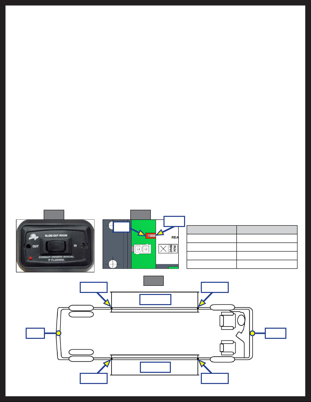
2. Determine location to mount the rocker switch (Fig. 5). The location needs to be in view of slide-out
room and have minimum depth of 1” inside the wall.
3. Route and attach the harness to where the rocker switch will be mounted, and mount the rocker
switch with 2 screws.
4. Label the motor leads at both ends to aid in connections at the control box and motors. Route the
motor/sensor harnesses from the slide-out room motors to the control box.
5. Set park brake signal input (Fig. 6):
A. 1510000236 control. With the switch in the left position (as shown) the control will be looking for
a park brake signal input. With the switch in the right position the control will be in bypass (not
looking for a park brake input signal).
Floor Roller (Not Supplied)
Fig. 3
Fig. 2
Fig. 4
Rev: 05.24.2016
Page 4
Slim Rack Slide-out Manual
B. 1510000276 control. With the switch in the left position (as shown) the control will be in bypass
(not looking for a park brake input signal). With the switch in the right position the control will be
looking for a park brake signal input.
6. If using the park brake feature, route the park brake input harness from the park brake signal source to
the control box.
NOTE: It is important that the slide-out motors be plugged in to the proper receptacle at the control box.
See (Fig. 7) below for proper slide-out motor designation. Failure to properly connect the motors to
the control will result in problems for future troubleshooting. (The control will identify the incorrect
motor during a fault).
7. Route and attach the proper gauge wire from the control to the 12V DC battery. It is recommended
that this circuit be protected with a 30 amp fuse. Wire must be sized so that a minimum of 12.5 VDC is
measured at the control while under load.
Fig. 5 Fig. 6
Right
Left
Wire Gauge Maximum Length
16 10 feet
14 15 feet
12 25 feet
10 40 feet
Fig. 7
Motor 1
Motor 2
Roadside
Rear Front
Rev: 05.24.2016
Curbside
Motor 2 Motor 1
Page 5
Slim Rack Slide-out Manual
 Loading...