

Handbook for the LT3500
Current Sensing Coin Operated Timer
Part Number 918-000-917 July 2011 Issue 3 (Version 50.0 )

Contents
Introduction . . . . . . . . . . . . . . . . . . . . . . . . . . . . . . . . . . . . . . . . . . . 1
Operational Features . . . . . . . . . . . . . . . . . . . . . . . . . . . . . . . . . . . . . 1
Installation . . . . . . . . . . . . . . . . . . . . . . . . . . . . . . . . . . . . . . . . . . . . . 2
Service Mode . . . . . . . . . . . . . . . . . . . . . . . . . . . . . . . . . . . . . . . . . . . . 3
Programming Current Sense . . . . . . . . . . . . . . . . . . . . . . . . . . . . . . . . 3
Programming Credit . . . . . . . . . . . . . . . . . . . . . . . . . . . . . . . . . . . . . . 4
Audit Functions . . . . . . . . . . . . . . . . . . . . . . . . . . . . . . . . . . . . . . . . . . 5
Other Functions . . . . . . . . . . . . . . . . . . . . . . . . . . . . . . . . . . . . . . . . . . 5
Operating Instructions . . . . . . . . . . . . . . . . . . . . . . . . . . . . . . . . . . . . . 6
Operating Meter . . . . . . . . . . . . . . . . . . . . . . . . . . . . . . . . . . . . . . . . . . 6
Money Counter . . . . . . . . . . . . . . . . . . . . . . . . . . . . . . . . . . . . . . . . . . 6
Error Messages . . . . . . . . . . . . . . . . . . . . . . . . . . . . . . . . . . . . . . . . . . 6
Appendix I . . . . . . . . . . . . . . . . . . . . . . . . . . . . . . . . . . . . . . . . . . . . . . 8
Appendix II. . . . . . . . . . . . . . . . . . . . . . . . . . . . . . . . . . . . . . . . . . . . . . 8
Specifications . . . . . . . . . . . . . . . . . . . . . . . . . . . . . . . . . . . . . . . . . . . 9
Contact Details:
Leisure Controls International Ltd
Clump Farm Industrial Estate, Higher Shaftesbury Road,
BLANDFORD FORUM, Dorset. DT11 7TD. United Kingdom
Telephone General Enquiries: +44 (0) 1258 489075/455393
Telephone Technical Support: +44 (0) 1258 483574
Fax: +44 (0) 1258 488526/456410
E-mail General Enquires: info@lcigb.com
E-mail Technical support: support@lcigb.com
Web Site: www.lcigb.com
LT3500 Installation and Operating Instructions 1
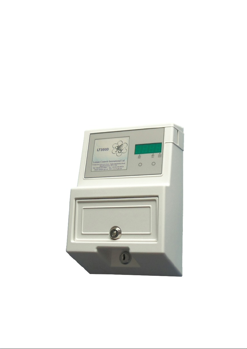
Introduction
Operational Features
The LT3500 incorporates a programmable current sense facility which stops the timer
counting down when the connected appliance is turned off. This is particularly useful
with applications such as air conditioning and heaters in apartments and community
halls where the user may turn off the heating or cooling when vacating the premises.
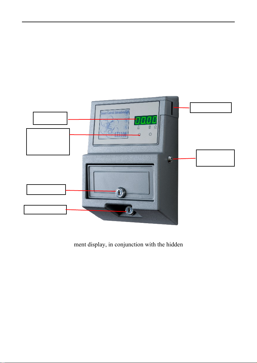
Coin Entry (2)
Display (1)
Hidden
programming
buttons (6)
Optional key
over-ride (3)
Cash box (5)
Cover Lock (4)
(1) The 4 digit 7 segment display, in conjunction with the hidden programming
buttons, is used to program the LT3500, as well as showing time remaining and
mode of operation (see Figure 4).
(2) The coin entry accepts tokens or 20p, £1, €½, €1 coins.
(3) The optional key over-ride switch turns the timer output on permanently.
(4) Access for installation is via the cover lock.
(5) Cash box holding 100 coins.
(6) Hidden programming buttons (page 3).
Figure 1 Main Features
2 LT3500 Installation and Operating Instructions
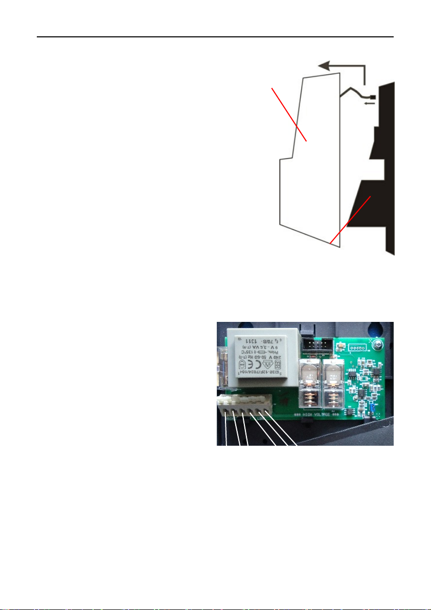
Installation
1) Unlock the front cover of the meter and lift
upwards slightly and away from the wall bracket
(see Figure 2). Unplug the cover flying lead from
the wall bracket and remove front cover.
2) The LT3500 should be mounted on a smooth
vertical wall making sure access to the side coin
entry is not obstructed. Take care to mount the case
level in both the vertical and horizontal axes;
failure to do so may prevent the coin mechanism
from operating correctly. Mark positions of the
mounting holes using the wall bracket as a
template and drill suitable holes in the wall. For
solid masonry use a 7 mm masonry drill bit and
plug holes with wall plugs sufficient for 38 mm
long screws. For wooden surfaces use a 3.5 mm
drill bit and screws of a minimum length of 15
mm; longer screws are advised for very soft
surfaces. Fit the top two screws to the wall leaving the head of the screw
approximately 7 mm from the surface. Hang the wall bracket on the wall, check that
the bracket is level and tighten the screws. Fix the bottom of the wall bracket to the
wall using the two remaining screws.
3) The timer will require a fused double
pole switch for the mains input. Wire the
unit as shown in Figure 3 using
appropriately rated and approved cable
conforming to the relevant regional
standards. The meter can either be
connected to the supply via a cable fed
through the hole at the bottom left hand
side of the wall bracket or through the
back of the meter. Ensure the cables are
secured underneath the cable clamps.
L N E
MAINS
Front
cover
Wall Bracket
Figure 2 Removing Cover
E N L
LOAD
4) Plug the flying lead from the cover to
the connector located in the wall bracket and fit the front cover onto the wall bracket,
drop down slightly and lock into place.
5) Apply power and the meter will briefly show ‘Pxx.x’ then any credit remaining
where xx.x is the version number of the firmware and should be quoted if requesting
technical assistance.
IMPORTANT: PROTECT THE INPUT BY A FUSE RELEVANT TO THE LOAD
Figure 3 Wiring Diagram

LT3500 Installation and Operating Instructions 3
Service Mode
The service mode consists of thirteen settings split in to four functional areas:-
1. Programming current sense values
2. Programming credit
3. Audit functions
4. Other functions
To access service mode remove the coin box, press and release button B (Figure 4) to
step to the desired setting number (St.01 to St.13). Simultaneously pressing and
releasing both buttons A and B will step back to the previous setting. On reaching the
required setting number press button A to enter desired values.
Parpadea cuando el
crédito excede las
100 horas.
Parpadea cuando la
pantalla muestra
minutos y segundos
Parpadea cuando se
está descontando
tiempo
Botón B
Botón A
Figure 4 - Front Panel
Programming current sense values
For the LT3500 to operate successfully the current consumption of the load must be
programmed at installation. It is recommended that the appliance is turned on and the
current monitored in both idle (low current value) and “in use” (high current value)
modes using setting St.11. With air conditioning units in particular it is advised to
check if there is an intermediate stage where the appliance has stopped cooling or
heating but enters a shut down mode which consumes current. This current should be
used as the idle current. The LT3500 should then be programmed for “in use” current
values and idle current values using settings St.13 and St.12 respectively.
St.11 Real time current reading
Press and release button B to step to setting number St.11. Press button A to enter
setting. The display shows a real time current reading in hexadecimal format (see

4 LT3500 Installation and Operating Instructions
the following messages initially: no.in There is no reply from the sensor (timer can not function correctly)
in.lo The value from the sensor is below the trigger level setup in ST.12.
trig The value from the sensor is above the trigger level setup in ST.13.
Press button A to switch to current display mode, this will show "i-xx", where xx is
the current reading as a value in hexadecimal format (see appendix 1); this value will
change as the load current consumption varies.
St.13 High current (In Use) Value
Press and release button B to step to St.13. Press button A to enter setting. Once
entered this mode will turn on the relays and the display will show "H-xx" to indicate
the stored hexadecimal setting for the high current mode. To learn a new current value,
set the load into its minimum high power state then press button A and wait as the
timer counts down from 8 to 0, with the display showing "C-xx", where xx is the count
down in seconds. If the value exceeds, equals or is just too close to the low value then
an "Err " will be displayed and no changes will be made; when a good value is
accepted it will be stored as the new setting. The display will return to showing the
current hexadecimal value for the high power state.
St.12 Low current (Idle) value
Simultaneously press and release both buttons A and B to step back to St.12. Press
button A to enter setting. Once entered this mode will turn on the relays and the
display will show "L-xx" to indicate the stored hexadecimal setting for the low current
mode. To learn a new current value, set the load to its idle state then press button A
and wait as the timer counts down from 8 to 0, with the display showing "C-xx",
where xx is the count down in seconds. If the value exceeds, equals or is just too
close to the high value then an "Err " will be displayed and no changes will be made;
when a good value is accepted it will be stored as the new setting. The display will
return to showing the current hexadecimal value for the low power state.
Programming credit
The credit functions allow the meter to be programmed for fixed time, session time or
session cost for charging purposes. Additionally a factory set option allows a
combination of session time and session cost. Once the initial cost is met further coins
will add time allocated to that coin. This is referred to as top-up mode.
Press and release button B to step to the desired setting number.
When the required number is showing on the display press and release button A to
display the existing setting. Press and release button A to select the digit to be changed
then press and release button B to alter that digit.
NOTE
Coins and tokens are validated by two coin sensors. Coin 1 sensor validates £1 coins,
L2 and L4 tokens. Coin sensor 2 validates €1, €½, 10p, 20p, L1 token

LT3500 Installation and Operating Instructions 5
St.01 Credit (Fixed Time) Per Coin 1
Sets the amount of credit given by coin sensor 1 (£1 coin, L2 or L4 tokens). Set in
HH.MM or MM.SS (When the meter is set in single coin or Totalise + Top Up mode).
St.02 Credit (Fixed Time) Per Coin 2
Sets the amount of credit given by coin sensor 2 (€1, €½, 10p, 20p coins or L1 token)
Set in HH.MM or MM.SS (When the meter is set in single coin or Totalise + Top Up
mode)
St.08 Maximum Credit (Lockout)
Sets the maximum amount of credit to be given at any one session (activated by
pressing the start button ‘A’). Set in HH.MM or MM.SS depending on the factory
configuration (entering zero disables this feature).
St.09 Totalise Value (Session Cost)
Sets the amount of money which needs to be inserted before any credit is given, e.g.
£1:20.
St.10 Totalise Credit (Session Time)
Sets the amount of credit given when the correct amount of money is inserted . Set in
HH.MM or MM.SS
Audit functions
Audit functions allow the operator to check the meter against cash receipts taken from
the coin box.
St.03 Total Money
Displays the total amount of money/tokens inserted since the last factory reset.
This is a read only display and cannot be changed.
St.04 Total Credit
Displays the total amount of credit given since the last factory reset.
This is a read only display and cannot be changed.
Also see resettable counter on page 6.
Other Functions
St.05, St.06, St.07 are settings used in other meters in the LT3000 range. They show as
00.00 on the display and are read only and cannot be altered.

6 LT3500 Installation and Operating Instructions
Operating Instructions
To Operate Meter
Insert coin/token. The display will briefly show ‘Coin’. The display will then show the
remaining credit. If the credit is greater than one hour it will be displayed in hours &
minutes, e.g.; 2 hours will be displayed as ‘02:00'. If the credit is less than one hour it
will be displayed in minutes & seconds, e.g.; 40 minutes will be displayed as ‘40:00'
and an indicator will flash on the display to show this (Figure 4).
Resettable Money (Token) Counter
When the coin box becomes full, the message ‘COLL’ (collect) is displayed.
Upon removal of the coin box the display will automatically show the resettable
money counter. This shows how much money has been inserted into the meter since
the last collection. When the coin box is reinserted, the money counter will
automatically zero before displaying the remaining credit.
Note: To prevent the money counter from zeroing, insert the coin box with ‘B’ pressed
Error Messages
Thirteen error messages are displayed to help fault finding in the unlikely event of
meter malfunction. Error messages are displayed in the format Er.xx
Er.01 Opto 1 detected an object not conforming to the required parameters.
Opto 1 is the coin sensor used to validate £1 coins, L2 & L4 tokens. If the
sensor detects that the coin is the wrong size it will show the error message.
Er.02 Opto 2 detected an object not conforming to the required parameters.
Opto 2 is the coin sensor used to validate 20p, 10p, €1, 50c coins or L1
tokens. If the sensor detects that the coin is the wrong size it will show the
error message.
Er.03 Not used
Er.04 Not used
Er.07 Opto 1 validated but St.01 is zero.
Set a value in St.01
Er.08 Opto 2 validated but St.02 is zero.
Set a value in St.02
Er.10 Meter configured in Totalise or Totalise + Top Up mode but St.09 is zero.
Set a value in St.09.
Er.11 Totalise + Top Up on £1 only (or token) meter but St.09 has fractional value.
Change St.09 to show whole number) e.g; 02.00.
Er.12 St.09 set with odd 10p on 20p meter. E.g. set to £1.50.

LT3500 Installation and Operating Instructions 7
If the following error messages are encountered contact the LCI support desk.
Er.05 Opto 1 validated but meter is configured as a 10p or 20p only.
Use CFG.1 – digit 1 to set the meter up for the correct coinage.
Er.06 Opto 2 validated but meter is configured as a £1 only.
Use CFG.1 – digit 1 to set the meter up for the correct coinage.
Er.09 Configuration number 1 (CFG.1), digit 2 is zero.
Digit 2 of CFG.1 must contain a vaue
SynC Software re-synchronising with the mains frequency

8 LT3500 Installation and Operating Instructions
Appendix I Hexadecimal
The value of the current being consumed by the appliance displayed by the LT3500 is
expressed in hexadecimal which is base 16. Humans use a base of ten (decimal) but
computers often use other bases such as two for the binary system. With base 16 the
characters representing numbers are zero to the letter F (0123456789ABCDEF). i.e.
the decimal value for '1' is represented in hexadecimal as '1' but the hexadecimal value
of decimal 15 is shown as 'F' and the value of decimal 17 is '11' in hexadecimal.
Decimal Hex Decimal Hex Decimal Hex
Decimal Hex Decimal Hex Decimal Hex
1 1 11 B 30 !1E
2 2 12 C 40 !28
3 3 13 D 50 !32
4 4 14 E 60 !3C
5 5 15 F 70 !46
6 6 16 10 80 !50
7 7 17 11 90 !5A
8 8 18 12 100 !64
9 9 19 13 500 !1F4
10 A 20 14 1000 !3E8
Appendix II Service Mode Settings
Setting Description Comment Setting Description Comment
St.01 Coin 1 credit HH:MM:SS St.08 Max. credit HH:MM:SS
St.02 Coin 2 credit HH:MM:SS St.09 Totalise value 0.00
St.03 Total Value Read Only St.10 Totalise time HH:MM
St.04 Total Time Read Only St.11 Actual current Hexadecimal
St.05 Not Used Read Only St.12 Low current Hexadecimal
St.06 Not Used Read Only St.13 High current Hexadecimal
St.07 Not Used Read Only

LT3500 Installation and Operating Instructions 9
Specifications
230V Models
Input 230V 50Hz 7A
Switching capacity 3kVA standard (13A resistive)
Power consumption Less than 22W in standby, no output load active
115V Models
Input 115V 60Hz 7A
Switching capacity 1.5kVA standard (13A resistive)
Power consumption Less than 22W in standby, no output load active
All Models
Fuses Type T HBC 250V breaking capacity, 20x5mm
100mA
Colour White
Time intervals Programmable minutes & seconds or hours & minutes
(99.99 Max)
Display 0.6 inch high green LED
Dimensions H: 270mm W: 183mm D: 93mm
Weight 1.4kgm
Case ABS
Lock Radial 8 pin with two keys
Cash box capacity 100 coins of 23mm diameter x 2.5mm thick
Service Information
The LT3500 meter has been designed to provide reliable long-term use for a variety of
timing applications. No regular servicing is required, apart from emptying of the cash
box.
Repairs
When reporting any fault with the timer it is useful to quote the serial number (located
on underside of the timer) and the firmware issue numbers first displayed when the
timer is turned ON. In most cases it is not necessary to remove the timer from the wall.
WARNING
Remove all sources of power from the timer before attempting any repairs.
Technical Support
Before contacting technical support please visit the support section of Leisure Controls
International’s web site at www.lcigb.com/support where many answers to questions
may be found.
Alternatively contact technical support directly by one of the following:-
E-mail: support@lcigb.com; Telephone: +44 (0)1258 483574; Fax: +44 (0)1258 488526

© 2011 Leisure Controls International Limited
 Loading...