

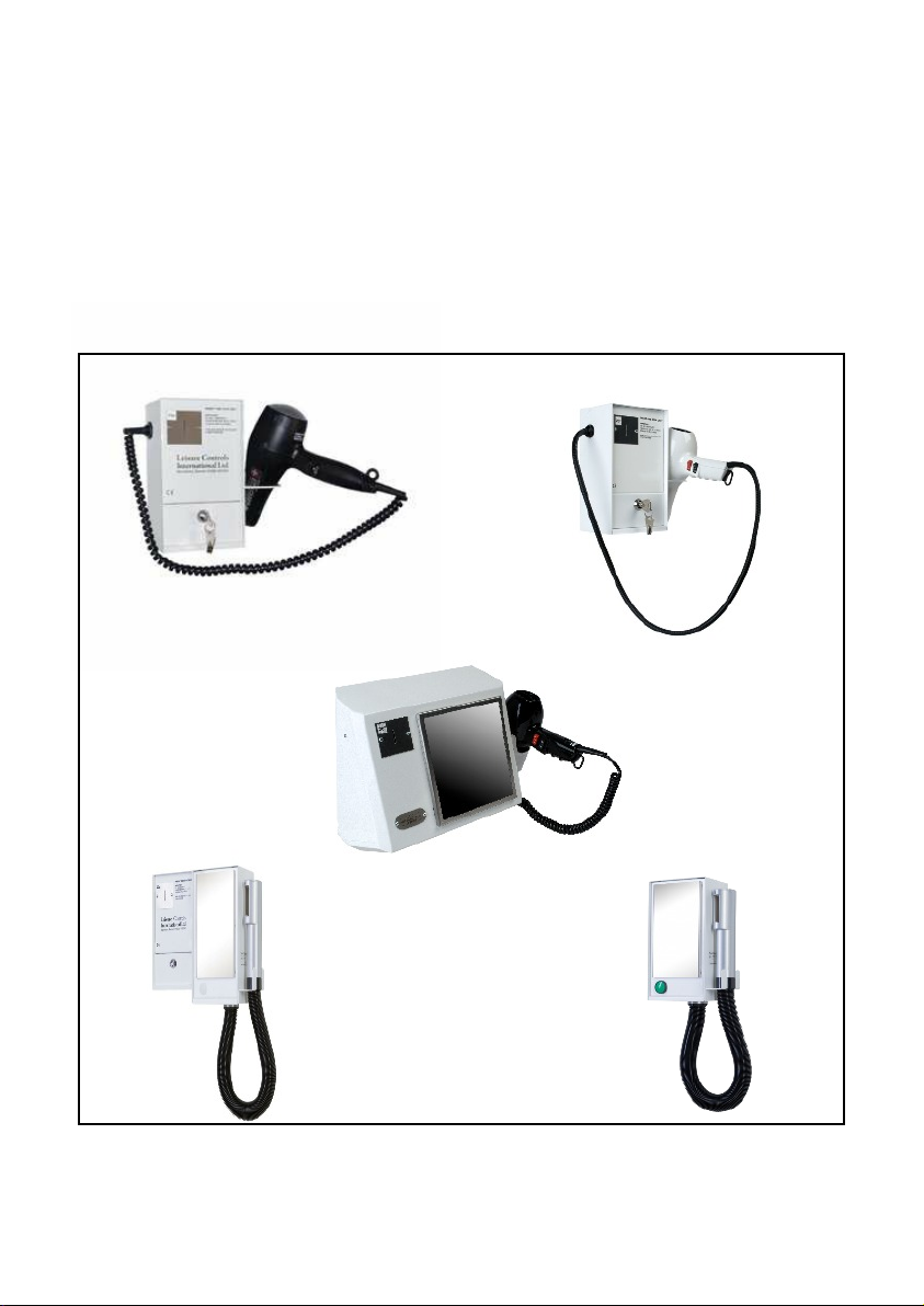
LCI HAIRDRYER RANGE
Coin, Token or Push Button
Operated
INSTALLATION AND OPERATING INSTRUCTIONS
Model A, Model B, Model C, Estelle
Issue 11 November 2018
Hairdryer Range 1
1. INTRODUCTION
The Leisure Controls International range of hairdryers is designed to give maximum reliability so
installation and after care instructions must be carefully followed to give optimum service. The modular
construction allows for easy servicing or replacement of parts when required. The meters comply with the
latest EMC and Low Voltage directives, meeting EN60730-1:92, EN50082-1:92, EN55014:93, and
EN60555-2:87.
2. INSTALLATION
All hairdryers, coin-operated or push-button models, are designed for wall mounting. Care should be taken
not to mount directly against a heat source or within three metres (ten feet) of running water. It is
recommended that the minimum height above the floor is 1.2 metres (four feet). Current IET wiring
regulations (BS 7671:2018) must be adhered to. It is recommended that each installation should be protected
by a suitable residual current breaker (RCB). A 30mA trip device will provide protection to within Zone 2.
2a. Model A, Model B and Model C (Coin-Operated)
i. Lay the meter on its back and unlock and remove the cash box.
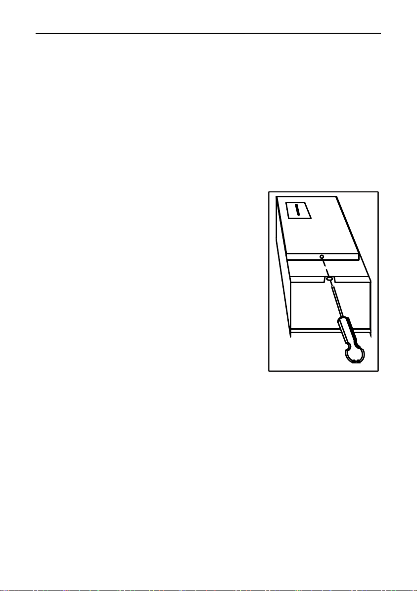
ii. See Figure 1. Using a No. 1, 9 inch pozidrive screwdriver remove
the recessed screw and remove the front panel by pulling towards
base as far as possible, lifting bottom edge slightly outwards and
then lifting panel upwards. IMPORTANT. It is essential that
panel recess is clear of case lip before attempting to lift panel out.
Rotate front panel and withdraw 5-way connector from printed
circuit board, thus separating front panel from the meter case. Set
programming switch (Section 3) and place panel in a safe place.
iii. Position the case on the wall and mark the top centre fixing
position. Drill and plug the wall and fit with No. 8 or 10 screw of
not less than 25mm (1”). Hang case on screw and tighten. Use a
spirit level to ensure the case is perfectly level.
If the case is not level the coin mechanism may malfunction.
Mark the bottom two screw positions, remove case and drill and
plug the holes.
iv. Remove the cable knockouts as required and fix to the wall.
v. Using a fused double pole switch for the mains input, wire
the unit as shown in Figure 2 using cable of cross sectional area
not less than 2.5mm2and fuse as appropriate up to a maximum of
10A. The use of 20mm conduit is recommended (use male thread adaptor with lock-ring e.g. Egatube
type EMA/2). Alternatively fit a 20mm nylon compression cable gland to provide strain relief.
WARNING!
THE EARTH TERMINAL MUST BE CORRECTLY CONNECTED TO A KNOWN EARTH
ENSURE EARTH WIRE IS ADEQUATELY TRAPPED BY THE TAGS OF THE CLAMPING WASHERS
vi. Refit front panel, making sure the 5-way connector is the correct way round. There is a polarising back
wall to ensure correct polarity. Forcing the connector the incorrect way round will cause
irreparable damage. Replace the recessed screw, making sure the screw head is flush with the front
panel but not over tightened.
vii. Insert cash box and lock. MAKE A NOTE OF THE KEY NUMBER AND PUT IN A SAFE PLACE.
viii. Switch on and test for correct operation.
NEVER OPERATE THE UNIT WITH THE FRONT PANEL UNSECURED OR WITH THE CASE UNEARTHED.
Front Panel Removal
Figure 1

Example set for 3 minutes
Hairdryer Range 2
Set Time (SW2)
MAINS
IN
HAIRDRYER
CONNECTION
EARTH
E
L N N L
Wiring connections for all versions
Figure 2
Set Time (SW1)
Position of programming switch (Models A, B, C)
Figure 4.
Switch numbers 1, 2 ON
= 3 minutes
To set time period
Figure 3.
Position of programming switch (Estelle)
Figure 5.
2b. Model C (Push Button-Operated)
i. Remove the screw from the bottom of the unit and lift the bottom edge of the front panel upwards. Pull
out gently and withdraw 5-way connector from the printed wiring board, thus separating the front panel
from the meter case. Place the panel in a safe place. Programme time as required using setting switches as
shown in figure 3.
ii. Position case on the wall and mark the top keyhole fixing position. Plug wall and fit No. 8 or 10 screw or
rawlbolt of not less than 25m (1"). Allow sufficient protruding to hang the case on the screw. Slightly
tighten screw and using a spirit level, mark position of the bottom two fixing holes ensuring the case is
level. Remove case and plug the wall holes.
iii. Remove conduit/cable knockout as required and fix case to the wall.
iv.
Using a fused double pole switch for the mains input, wire the unit as shown in Figure 2 using cable of
cross sectional area not less than 2.5mm2 and f
of 20mm conduit is recommended (use male thread adaptor with lock-ring e.g. Egatube type EMA/2).
Alternatively fit a 20mm nylon compression cable gland to provide strain relief.
THE EARTH TERMINAL MUST BE CORRECTLY CONNECTED TO A KNOWN EARTH
ENSURE EARTH WIRE IS ADEQUATELY TRAPPED BY THE TAGS OF THE CLAMPING WASHERS
It is recommended that push-button models are set for a maximum of two minutes.
use as appropriate up to a maximum of 10A. The use
WARNING!

Hairdryer Range 3
v. Refit front panel, making sure the 5-way connector is the correct way round. There is a polarising back
wall to ensure correct polarity. Forcing the connector the incorrect way round will cause
irreparable damage. Replace the fixing screw ensuring the front panel is securely fitted but not over
tightened.
vi. Switch on and test for correct operation.
2c. Estelle (Coin and Push Button Operated)
i. Open the casing by using the keys provided. Remove the coin tray for easy access. Remove the screw
holding the safety cover and remove the cover. Decide the desired position for the box on the wall,
bearing in mind the extra width necessary when the door is open and allowing sufficient room
above a table top to access the lock! Ensure the position is at least 3 metres from running water.
ii Mark the wall to indicate the position of the top centre screw and drill and plug this to take a No. 8 or 10
screw of at least 25mm (1”) in length, depending on the wall structure. Insert the screw leaving it loose
enough to hang the box, ensuring that it is as level as possible. Check with a spirit level and mark the
position of the other four fixing holes on the wall. Remove the box and drill and plug the four additional
holes with suitable fixings. Remove the cable knockout if bottom entry required and fix case to the wall.
IMPORTANT. If the case is not level the coin mechanism may malfunction.
iii. Using a fused double pole switch for the mains input, wire the unit as shown in Figure 2 using cable of
cross sectional area not less than 2.5mm2 and fuse as appropriate up to a maximum of 10A. The use
of 20mm conduit is recommended (use male thread adaptor with lock-ring e.g. Egatube type EMA/2).
Alternatively fit a 20mm nylon compression cable gland to provide strain relief.
WARNING! THE EARTH TERMINAL MUST BE CORRECTLY CONNECTED TO A KNOWN EARTH
ENSURE EARTH WIRE IS ADEQUATELY TRAPPED BY THE TAGS OF THE CLAMPING WASHERS
iv. Programme time as required using setting switches as shown in figures 3 and 5.
push-button models are set for a maximum of 2 minutes.
v. Replace the safety cover and the coin box, close and lock the door. Re-apply mains and check correct
operation of the coin mechanism and the whole installation.
It is recommended that
3. AFTER CARE
It is essential that all dryers are kept clean and free from dirt and fluff at the air inlet. Regular
cleaning is essential for maximum life of all models. Daily inspection is recommended.
WARNING! Failure to keep air intakes clear will impair performance and could lead to over-heating and
subsequent damage or intermittent cut-out and could invalidate the guarantee.
3a. Model A, Model B and Estelle
All handsets are fitted with a dust filter. To clean, remove filter holder and gauze, remove any hair from the
inlet and rinse and dry gauze. Extra filters are available.
WARNING! When in use the hairdryer must be kept clear of all obstruction and the air inlet never be
covered with towels or clothing when running.
WARNING! Cables must be regularly checked for signs of wear and replaced as soon as any damage is
observed. Failure to do so invalidates the guarantee and could be a health hazard.
Although the coin timer is strong and reliable the cash box is an obvious target for vandalism. It is recommended that coin boxes are emptied every evening and Model A and B coin boxes are left unlocked.
3a. Model C (Coin and Push Button Operated)
To clean Model C dryer remove the front panel (see Section 2b.i) and remove the heater by slackening the
two screws holding the heater retaining bracket at the top of the unit, slide the bracket upwards and
ease the heater out. Inspect the air intake and remove any trapped dirt. Replace in reverse order.
Inspect the tube and nozzle regularly.
Designed and manufactured in Great Britain by Leisure Controls International Ltd.
BLANDFORD FORUM, Dorset, DT11 7TD. United Kingdom
Edition 11 November 2018 918-000-226
 Loading...