


1
LED PAR 64-18-QUAD-COLOR
Please read t he instructions carefully before use
LCG-079
User Manual

2
1. SAFETY INSTRUCTIONS:
• Please keep this User Manual for future consultation. If you sell the unit to
another user, be sure that they also receive this instruction booklet.
• Unpack and check carefully there is no transportation damage before using the
fixture.
• Before operating, ensure that the voltage and frequency of power supply match
the power requirements of the fixture.
• It’s important to ground the yellow/green conductor to earth in order ot avoid
electric shock.
• Disconnect main power before servicing and maintenance.
• Use safety chain when fixes this fixture. Don’t handle the fixture by taking its
head only, but always by taking its base.
• Maximum ambient temperature is TA: 40°C. Don’t operate it where the
temperature is higher than this.
• The unit is for indoor use only. Use only in a dry location.
• Don’t connect the device to any dimmer pack.
• Make sure there are no flammable materials close to the unit while operating, as
it is fire hazard.
• The housing or the lenses must be replaced if they are visibly damaged
• Do not allow children to operate the unit.
• Replace fuse only with the same type.
• Never try to repair the unit by yourself. Repairs carried out by unskilled people
can lead to damage or malfunction. Please contact the nearest authorized
technical assistance center.
• Disconnect the mains power if the unit is not used for a long time
• Do not look directly at the Led Light beam while the unit is on
• To prevent or reduce the risk of electrical shock or fire, do not expose the fixture
to rain or moisture.
2. INSTALLATION:
• The unit should be mounted via its screw holes on the bracket. Always ensure
that the unit is firmly fixed to avoid vibration and slipping while operating.
Always ensure that the structure to which you are attaching the unit is secure
and is able to support a weight of 10 times of the unit’s weight. Also always use
a safety cable that can hold 12 times of the weight of the unit when installing the
fixture.
• The unit must be fixed by professionals. And it must be fixed at a place where is
out of the touch of people and has no one pass by or under it.

3
3. TECHNICALS SPECIFICATIONS
• Led: 18 x 8W QUAD RGBW
• Each Led is 8W ( each color is 2W )
• Beam angle: 40°
• Black and short housing
• Dual yoke for floor mounting
• Led display
• 3 Pin XLR In and Out
• Thermal protection
• Cooling system
• Operations Modes: Built-in Program / Auto Run / DMX / Master Slave / Sound
Activated
• DMX-512: 1 / 4 / 4 / 4 / 5 / 5 / 7 channels selectable
• Power Consumption: 160W
• Power supply: 120V-60Hz
• Size: 31 x 23 x 23 cm
• Weight: 3.0 kg
4. OPERATIONS:
1. BUILT-IN Program
4
a. Press MODE button, Pr
b. Press UP or DOWN button, select the effect program Pr-01-Pr.11. When
LED display show Pr.01, press SETUP button enter edit the static color,
press UP or DOWN button , can select 14 kinds of static colors built-in
program (1.-r ; 2-rg; 3.-g; 4.-gb; 5.-b.; 6.-rb; 7.-rgb; 8-w; 9.-FL; 10.-rw; 11.gw; 12.-bw; 13.-yw; 14.-uw), Press SETUP again , trough UP or DOWN
button adjust the brightness, press SETUP button can setup the flash
“FSxx”, trough UP or DOWN button, adjust the speed of the flash FS00FS99.
When LED display show Pr.02-Pr.11, the first press SETUP button, will be
show “SP.XX”. Now trough UP or DOWN setup the running speed SP01Sp100(FL). The second time press SETUP button, will be show “FSxx”, now
can through UP or DOWN button setup the speed of flash FS00-FS99.
2. Auto run mode
Press MODE button, enter auto run mode menu “AUTO”, The light will be
auto run 10 kinds od built-in program Pr.02-Pr.11. The user setup the
built-in program Pr.02-Pr.11 like running speed, flash speed, the setting
program will be auto run in order.
3. DMX mode
A. Press MODE button, enter DMX mode menu “d..xxx »
B. Press UP or DOWN button, setup DMX address d.001-d.512
C. Press SETUP button, setup DMX mode menu X-ch
D. Press UP or DOWN button, setup DMX mode 1-ch, 4-ch-1, 4-ch-2, 4-ch-3, 5-ch-1,
5-ch -2, 7-ch
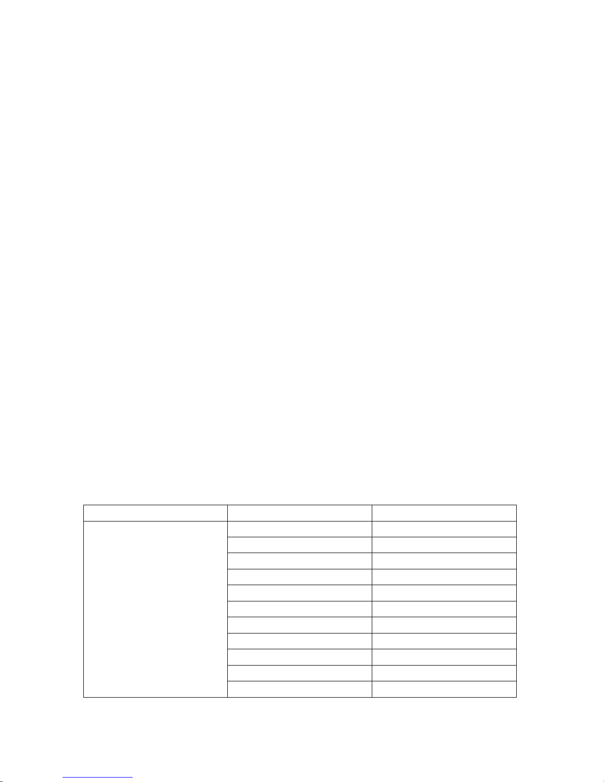
DMX MODE 1: 1 CHANNEL (1 CH)
CHANNEL VALUE FONCTION
0-22 Red
23-45 Green
46-68 Blue
69-91 Lite Blue
92-114 Yellow
CH 1
115-137 Orange
138-160 Lite Pink
161-183 Pink
184-206 UV
207-229 Lite Green
230-252 Cold White
5
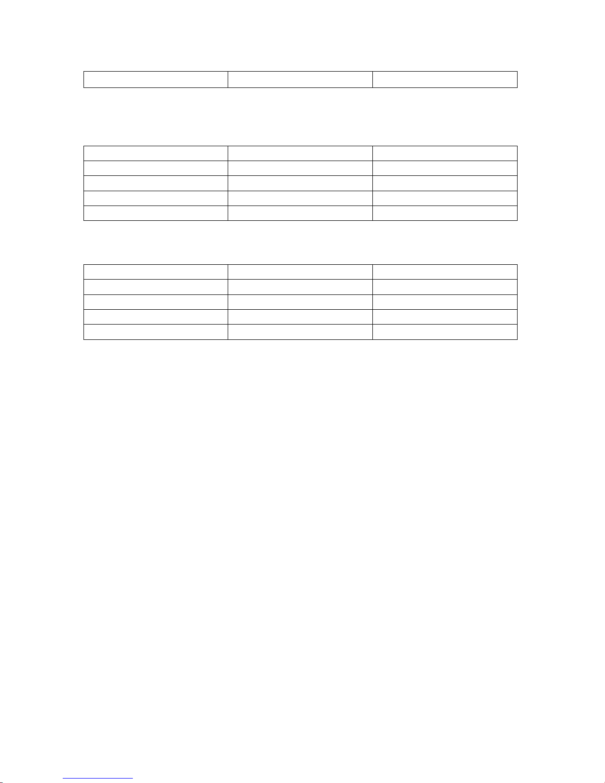
DMX MODE 2: 4 CHANNELS (4C-1)
CHANNEL VALUE FUNCTION
1 0-255 RED
2 0-255 GREEN
3 0-255 BLUE
4 0-255 DIMMER
DMX MODE 3: 4 CHANNELS (4C-2)
CHANNEL VALUE FUNCTION
1 0-255 RED
2 0-255 GREEN
3 0-255 BLUE
4 0-255 WHITE
253-255 Warm White

6
DMX MODE 4: 4 CHANNELS (4C-3)
CHANNEL
VALUE
FUNCTION
CHANNEL VALUE FUNCTION
1 0-255 DIMMER
2 0-255 RED
3 0-255 GREEN
4 0-255 BLUE
DMX MODE 5: 5 CHANNELS (5C-1)
1 0-255 RED
2 0-255 GREEN
3 0-255 BLUE
4 0-255 WHITE
5 0-255 DIMMER
DMX MODE 6: 5 CHANNELS (5C-2)
CHANNEL VALUE FUNCTION
1 0-255 DIMMER
2 0-255 RED
3 0-255 GREEN
4 0-255 BLUE
5 0-255 WHITE
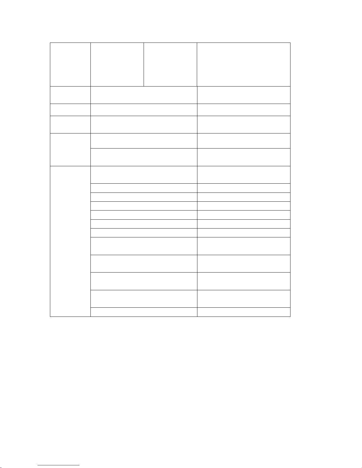
DMX MODE 7: 7 CHANNELS (7C)
CHANNEL VALUE FUNCTION
CH1 0-255 Master dimming
CH2
Red color
dimming
43 kinds of
static color can
be chosen ( it is
available when
the 7ch is 0-22)
Speed
adjustion
( control the
program speed
of CH7 (23-252)
0-255 Red color dimming
Move each 5 to
change another
43 kinds of static color
color
0-255 slow-fats
0-255
selected)
7
When CH7 is
Pr08 (red color gradual
between 253255, it can ajust
the sound
0-255
Adjust the sound sensitivity
sensitivity
CH3
0-255
Green color dimming 0-255
CH4 0-255 Blue color dimming 0-255
CH5 0-255
CH6
0-9 NO FUNCTION
10-255
1-22
23-45 Pr02 (gradual change1)
46-68 Pr03 (gradual change2)
69-91 Pr04 (jumping change1)
92-114 Pr05 (jumping change2)
115-137 Pr06 (fantasy change1)
138-160 Pr07 (fantasy change2)
Cool white color dimming 0-
255
STROBE ( slow-fats)
In CH2 can choose 43 kinds of
static color
CH7
161-183
184-206
207-229
230-252
change)
Pro9 (green color gradual
change)
Pr10 (blue color gradual
change)
Pr11 (cool white color gradual
change)
253-255 Sound active mode
On mode 7, When CH7 on 0-22, CH2 can choose the static color of built-in program, but
the function of red color dimming will be temporary failure: CH3,CH4 will be temporary
failure. CH7 on 23-252, Ch2 adjust the speed of built-in program of the CH7, but the
function of sound active, the CH2 can adjust the sensitivity of sound active, but the
function of red color dimming will be temporary failure: CH3, CH4, CH5 will be
temporary failure. The CH7 not as 0, on CH2, CH3, CH4, CH5 the function of red
color/blue color/green color/cool white dimming will be temporary failure.
5. MASTER/SLAVE MODE
Press MODE button, enter slave mode “SLAV”

8
The effect program of the master light on Built-in program, auto run or sound active
mode is the same with the slave light.
6. SOUND ACTIVATED MODE:
A. Press MODE button ,enter sound active mode “SU.xx”.
B. Press UP or DOWN button, setup the value sensitivity of sound active SU.00-SU.31

9
7. DMX512 CONNECTIONS:
INPUT
OUTPUT
COMMON
DMX +
DMX -
DMX 512
120 OHM 1/4W
The DMX512 is widely used in intelligent lighting control, with a maximum of 512
channels.
• 1
• 3
• 2
• 1
• 3
• 2
Termination reduces signal errors and to avoid signal transmission problems and interference. It is always
advisable to connect a DMX terminal. (resistance 120ohm 1/4W ) between pin2 (DNX-) and pin3 (DMX+)
of the last fixture.
1. Connect the fixture together in a “daisy chain” by XLR plug cable from the output
of the fixture to the input of the next fixture. The cable cannot be branched or
split to a 2Y” cable. Inadequate or damaged cables, soldered joints or corroded
connectors can easily distort the signal and shut down the system.
2. The DMX output and input connectors are pass-through to maintain the DMX
circuit when no power is connected to the fixture.
3. At last fixture, the DMX cable has to be terminated with a terminator to reduce
signal errors. Solder a 120-ohm 1/4W resistor between pin 2(DMX-) and pin
3(DMX+) into a 3-pin XLR-plug and plug it in the DMX-output of the last fixture.
4. Each lighting fixture needs to have an address set to receive the data sent by the
controller. The address number is between 0-511 (usually 0 & 1 are equal to 1).

10
5. 3 pin XLR: Pin 1: GND, Pin 2: Negative signal (-), Pin 3: Positive signal (+).
Notice:
A. If no any touch the button within 20 seconds, the LED display will be close, if touch
any button at this time, the LED display will be recover the original status. All the button
will be recover the function,
B. This light have the excess temperature self defective function. When the brightness is
obvious reduce, please check if the fan work in normal, after clear the trouble clear,
please power supply, the light will be release defend, and work in normal.
8. TROUBLESHOOTING
Following are a few common problems that may occur during operating. Here are some
suggestions for easy troubleshooting:
• The fixture does not work, no light & the fan does not work:
1. Check the connection of power and main fuse.
2. Measure the mains voltage on the main connector.
• Not responding to DMX controller:
1. DMX LED should be on. If not, check DMX connectors, cables to see if link
properly.
2. If the DMX Led is on and no response to the channel, check the address settings
and DMX polarity.
3. If you have intermittent DMX SIGNAL problems, check the pins on connectors or
on PCB of the fixture or the previous one.
4. Try to use another DMX controller
5. Check if the DMX cables run near or run alongside to high voltage cables that
may cause damage or interference to DMX interface sircuit.
• No response to the sound:
1. Make sure the fixture does not receive DMX signal
2. Check microphone to see if it is good by tapping the microphone.
• One of the channels is not working well:
1. The stepper motor might be damaged or the cable connected to the PCB is
broken
2. The motor’s drive IC on the PCB might be out of condition.
9. FIXTURE CLEANING:
The cleaning of internal must be carried out periodically to optimize light output.
Cleaning frequency depends on the environment in which the fixture operates: damp,
smoky or particularly dirty surrounding can cause greater accumulation of dirt on the
fixture’s optic.
• Clean with soft cloth using normal glass cleaning fluid.
• Always dry the parts carefully

11
• Clean the external optics at least every 20 days. Clean the internal optics at least
every 30/60 days.
 Loading...