

www.lc-group.ca
USER MANUAL
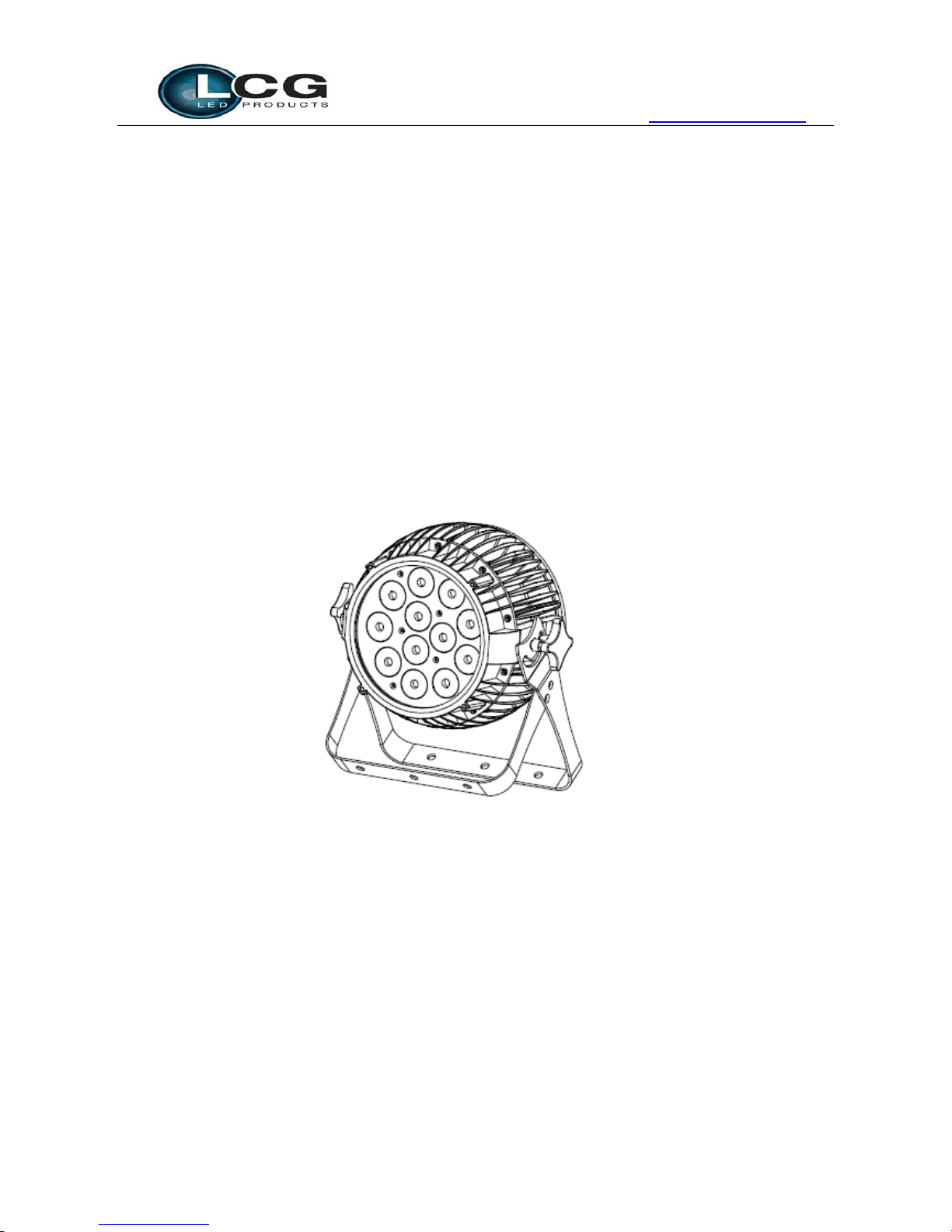
BEAMER6
LCG-1212S
(12x 12W-RGBAWU 6-in-1
)

www.lc-group.ca
Catalogue
1. Summary ................................................................................................................ 1
2. Safety Instruction ................................................................................................... 2
3. Outside Size Picture ............................................................................................... 3
4. Main Function ........................................................................................................ 4
5. DMX Control Function ............................................................................................ 5
6. Display Operation instruction ................................................................................ 7
7. Operating Control Instruction .............................................................................. 13
8. XLR cable connecting ........................................................................................... 13
9. Connecting picture ............................................................................................... 14
10. Trouble Shooting .................................................................................................. 15
Please read over this manual before operating the light

www.lc-group.ca
1
1. Summary
Summary
Thank you for purchasing our BEAMER6. Please read these instructions carefully before begin
and
operate the fixt ur es a cc ord in g to t hes e ins tr uc tio ns to avo id a ny poss ib le d am a ge s and
accidents cause s
by misusage
P
roduct introduction
BEAMER6 light uses casting aluminum housing
, designed in a fashion of hydrodynamic form.
Appearance shows. It adopts high power
6-in-1
LED, which refers to single LED is made of
R,G,B,A,W,UV 6-IN-1 LED, And long life span, low consumption, good
color mixing effect and high
brightness are the most prominent features. Each kind of LED can be independently dimmed. The built-in
program includes dimming, strobe, eotic, gradual change, fading and so on.
It uses power switch, performs
low weight and consumption, stable
capability and long life. International standard DMX 512 signal is
requested.
P
acking List
BEAMER6 (LCG-1212S) 1 PC
Waterproof input power cable 1 PC & Waterproof ouput power cable 1 PC
DMX Signal Cab
le 1 Set & Connector 1 PC
User Manual
Warranty Card

www.lc-group.ca
2
2. Safety Instruction
Safety Notes
! Enquire the skilled people before any repair;
! Always make sure disconnect from the power source before setting up, serving and moving;.
! Avoid direct eye exposure to the fixture when it is on;
Safety instruction
● Make sure the power supply voltag e are con s is tent with this ligh ts,Ensure the use of voltage is in the range
o
f the request technical parameter.
●Before the installation, please check the light’s fasteners and mechanical structure have been received i
n
go
od condition and appear no damage
.
●
This light is designed for indoor use;
working
temperature is low er than 40 de gre e.
●T
he fixtures maybe mounted in any position provided there is adequate room for ventilation. Make sure
there are no inflammable and explosive items (ornaments) in 0.5 meters away.
●Yellow / green cabling earthling safety; no flicker when the fixture is working o
n.
www.lc-group.ca
3
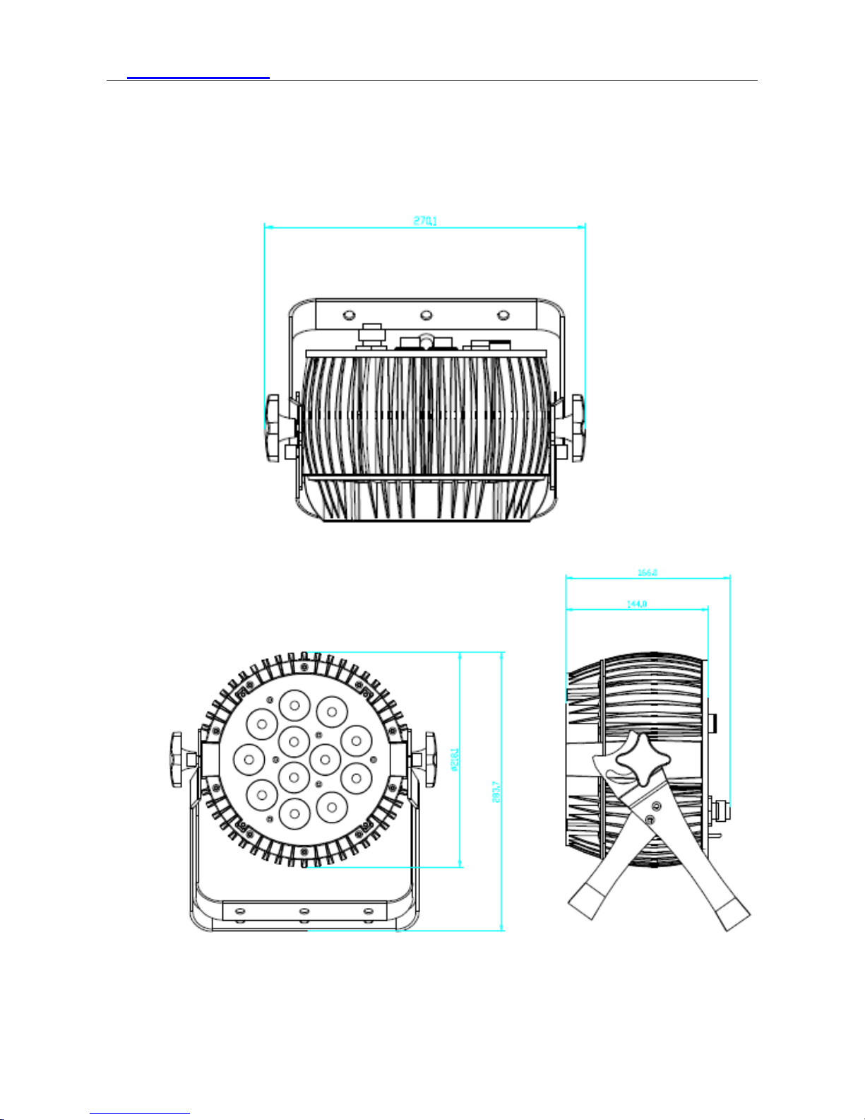
3. Outside Size Picture

www.lc-group.ca
4
4. Main Function
Input voltage: AC 100V-264V/47-63HZ
Consume:150W
Lamp Type:12W LED 6-in-1 R、G、B、A、W、UV (12PCS)
Life span: 50000~100000hours
PWM Dimmer:1500HZ(16666 grades)
Control Signal:DMX512
Control mode:stand alone/ sound activated
Channel:12CH、9CH、7CH、6CH、5CH、4CH
Function Effect: dimmer, strobe, gradual change
Touch buttons, automatic lock key
Built-in temperature control measurement function, when LED work overheated, intelligent reduce LED
output power, current power output can be viewed
Cooling mode: Natural Convection
Anti-electricity intension:1.5KV
Insulation Resistance:>2MΩ
Size:287.3*270.1*166.0mm
Net Weight: 5.2 Kg
Beam Angle: 25°
Protection grade: IP65

www.lc-group.ca
5
5. DMX Control Function
DMX Channels
4CH
5CH
6CH
7CH
9CH
12CH
VALUE
FUNCTION
- CH1 - CH1 CH1 CH1 0-255 Dimming all
CH1
-
CH1
CH2
CH2
CH2
0-255
Red
CH2
-
CH2
CH3
CH3
CH3
0-255
Green
CH3
-
CH3
CH4
CH4
CH4
0-255
Blue
-
CH2
CH4
CH5
CH5
CH5
0-255
Amber
CH4 CH3 CH5 CH6 CH6 CH6 0-255 White
- CH4 CH6 CH7 CH7 CH7 0-255 UV
- - - - CH8 CH8
0-5 No strobe
6-20 Not synchronous strobe(slow to fast)
21-60 Synchronous strobe(slow to fast)
61-100
Electronic Sinewave(slow to fast)
101-140
Random Strobe(slow to fast)
141-180
Opening pulse(slow to fast)
181-220
Closing pulse(slow to fast)
221-255
Electronic Squarewave(slow to fast)
- - - - -
CH9(CH
9 prior to
CH11)
0-10
No effect
11-15 CT01(call custom color setting CT01)
16-20 CT02
21-25 CT03
26-30 CT04
31-35 CT05
36-40
CT06
41-45
CT07
46-50
CT08
51-55
CT09
56-60
CT10
61-65
AUTO 1
(R,G,B,A,W,UV,RG,RB,GB,AW,WUV,AUV)
66-70
AUTO 2
(R↑,R↓,G↑,G↓,B↑,B↓,A↑,A↓,W↑,W↓,UV↑,UV↓)
71-75 AUTO 3 (R↑G↑,R↓G↓,R↑B↑,R↓B↓,B↑G↑,B↓G↓)
76-80 AUTO 4 (R↑G↑B↑W↑,R↓G↓B↓W↓)
81-85
AUTO 5 (Rainbow effect:
B,BG↑,BG,B↓G,G,GR↑,GR,G↓R,R,RB↑,RB,R↓
B)
86-90
CHASE 1

www.lc-group.ca
6
91-95
CHASE 2
96-100
CHASE 3
101-110
Reserved
111-200
R:111-115,G:116-120,B:121-125,A:126-130,W:1
31-135,UV:136-140,YELLOW:141-145,PINK:1
46-150,CYAN:151-155,ORANGE:156-160,VIO
LET:161-165,GOLDEN:166-170,2700K:171-175
,3200K:176-180,4000K:181-185,5500K:186-190,
6500K:191-195,RGBW:196-200
201-255 Reserved
- - - - - CH10 0-255
0-255(S),(speed of AUTO, fast to slow,when
AUTO1-AUTO5 effective)
- CH5 - - -
CH11
(RGB
color
mixing
instead of
RGB
channels
but A W
UV
channels
not
affected)
0-10 No effect
11 Blue (Blue=full, Red+Green=0)(step)
12-50 Red=0, Green->up,Blue =full(proportional)
51 Light Blue (Red=0, Green=full, Blue =full)(step)
52-90
Red=0, Green=full, Blue->down(proportional)
91
Green (Red=0, Green=full, Blue =0)(step)
92-130
Red->up, Green=full, Blue=0(proportional)
131
Yellow (Red=full, Green=full, Blue=0)(step)
132-170
Red=full, Green->down, Blue=0(proportional)
171 Red(Red=full, Green=0, Blue=0(step)
172-210 Red=full, Green=0, Blue->up(proportional)
211 Magenta (Red=full, Green=0, Blue=full)(step)
212-250 Red -> down, Green=0, Blue=full(proportional)
251-255 Blue (Red=0, Green=0, Blue=full)(step)
- - - - CH9 CH12
0-10
Use the dimmer mode which menu had set up
11-20
Linear curve and not smooth
21-30
Square law curve and not smooth
31-40
Inverse square law curve and not smooth
41-50 S-curve and not smooth
51-60 Linear curve and smooth
61-70 Square law curve and smooth
71-80 Inverse square law curve and smooth
81-90 S-curve and smooth
91-255
Use the dimmer mode which menu had set up

www.lc-group.ca
7
6. Display Operation instruction
MENU : access the menu or return to a previous menu option
ENTER: select the current menu option
UP: menu selection or parameter increments
DOWN: menu selection or parameters decrease
Menu Tree
Tab
Level 1
Level 2
Level 3
Level 4
ADDR(Address)
001-512
STAT(Static
control)
R 0-255*
G
0-255*
B
0-255*
A
0-255*
W 0-255*
UV 0-255*
SHUT 0-255*
PR
SC(Preset
color)
NONE,R,G,B,A,W,UV,YELLO
W,PINK,CYAN,ORANGE,VI
OLET,GOLDEN,2700K,3200K
,4000K,5500K,6500K,RGBW*
SET(Set) CAL(Calibration) R(Red) 0-255
G(Green) 0-255
B(Blue) 0-255
A 0-255
W
0-255
UV
0-255
USE
YES/NO
CHMD(Channel
12CH

www.lc-group.ca
8
mode)
9CH
7CH
6CH
5CH
4CH
DIM(Dimming
mode)
LIN/SQR/ISQR/SCUR/LIN.
/SQR./ISQR/SCUR.
DISY(Display
set)
ON(Permanent on)
2MIN (2 minutes off)
LOCK(Key 2
minutes lock)
YES/NO
CTST(Custom
color set)
CT01 R(Red) 0-255
. G(Green) 0-255
. B(Blue) 0-255
. A 0-255
. W 0-255
. UV 0-255
CT10
AUTO(Auto)
AT01
0-255*
AT02
0-255*
AT03
0-255*
AT04
0-255*
AT05 0-255*
CHS1 RUN..*
CHS2 RUN..*
CHS3 RUN..*
PROG
(Program)
CHS1(Chase 1)
SC01(Scene 1)
R(Red) 0-255
. . G(Green) 0-255
. . B(Blue) 0-255
. . A 0-255
. . W
0-255
. . UV
0-255
. . SHUT
0-255
. . AUTO
NONE,AT01-AT05
. . ATSP
0-255(S)
. . TIME 0-255(S)
. . WAIT 0-25.5(S)
. . USE YES/NO
.
SC20(Scene 20)

www.lc-group.ca
9
CHS3(Chase 3)
INFO
(Information)
SOFT(Software
version)
Vx.x
P
OW(Power
reduction)
100%/80%/50%
LOAD(Load)
ST L(
Setting
load)
YES/NO
PR L(Program
load)
YES/NO
SEND(Send)
YES/NO
In
structions
:
When enter to the “*” position displayed on the LED, the light will automatically set as master and send data to
external. Other fixtures can receive this data and will synchronously running without manually set as slave. When
power cycle it will jump to the “*” position and running again. And in these position it will not return back to the
default display after two minites.
6.1 DMX ADDRESS SETTING
1) Press the 【ENTER】 button in 【ADDR】 menu, then enter to the DMX address setting.
2
) P
ress the【UP/DOWN】button to select【1-512】numerical value.
3
) P
ress the【ENTER】button to escape and save.
6.2 STATIC SETTING
1) Press the【ENTER】button in 【STAT】menu, then enter to the static setting.
2
) P
ress the【UP/DOWN】 button to select 【RED】,【GREEN】,【BLUE】,【AMBER】,【WHITE】
,【UV】and【SHUT】.
3
) P
ress the【UP/DOWN】button to set up the【0-255】numerical value.
4
) P
ress the【ENTER】button to escape and save.
6.3 COLOR CAST CALIBRATION SETTING
1) Press the【ENTER】button in 【CAL】menu, then enter to the color cast calibration setting.
2
) P
ress the【UP/DOWN】button to select 【RED】,【GREEN】,【BLUE】,【AMBER】,【WHITE】,
【UV】
3
) P
ress the【UP/DOWN】button to set up the【0-255】numerical value.
www.lc-group.ca
10
4) On the【USE】interface, pressing【YES】button means valid,【NO】means invalid.
5
) P
ress the【ENTER】button to escape and save.
Illustrations: When pressing the【YES】button which means valid on the【USE】interface, the actual output value
of RED,GREEN,BLUE,AMBER,WHITE, UV is output in accordance with the percentage which the color
cast calibration value divides 255.
6.4 CHANNEL MODE SETTING
1) Press the【ENTER】button in 【CHMD】menu, then enter to the channel mode setting.
2
) P
ress the【UP/DOWN】button to select【12CH】,【9CH】,【7CH】,【6CH】,【5CH】,【4CH】
3
) P
ress the【ENTER】button to escape and save.
6.5 DIMMING MODE SETTING
1) Press the【ENTER】button in【DIM】menu, then enter to the dimming mode setting.
2)Press the【UP/DOWN】button to select【LIN】,【SQR】,【ISQR】,【SCUR】,【LIN.】,【SQR.
】,【ISQR.】and【SCUR.】.
3
) P
ress the【ENTER】button to escape and save.
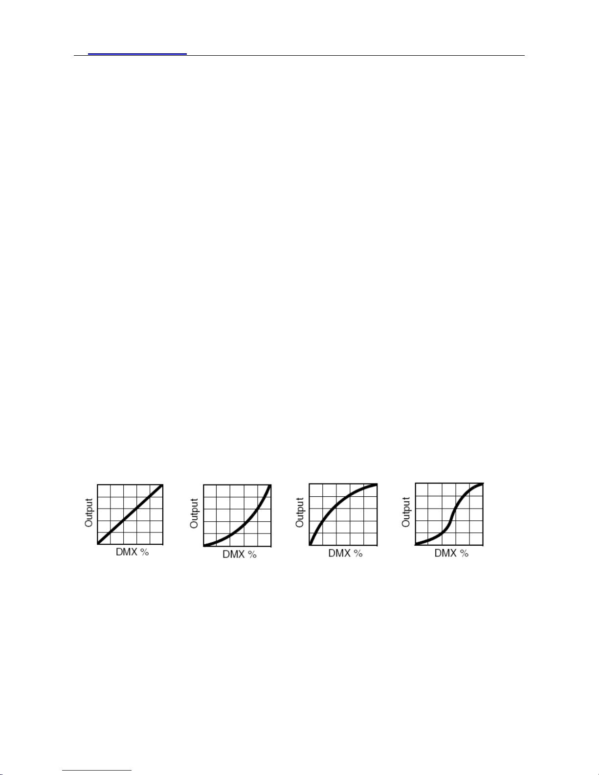
Illustrations:When setting【LIN.】,【SQR.】,【ISQR.】and 【SCUR.】 in 【DIM】 menu, there will be
added a little delay dimming effect for smooth..
Dimming curve:
Linear curve: square law curve: Inverse Square law curve: S-curve:
6.6 DISPLAY SETTING
1) Press the【ENTER】button in【DISY】menu, then enter to the display setting.
2
) P
ress the【UP/DOWN】button to select【ON】,【2 MINITES OFF】
3
) P
ress the【ENTER】button to escape and save.
6.7 A UTO LOCK KEY SETTING
1) Press the【ENTER】button in【LOCK】menu, then enter auto lock key setting.

www.lc-group.ca
11
2) Press the【UP/DOWN】button to select【YES】,【NO】
3
) P
ress the【ENTER】button to escape and save.
Instructions:
When set to [YES], it will lock automatically after two minutes to prevent accidental triggering flood
flushing, and then press any key for 10 seconds to unlock.Sametimes it will display decreasing time 10,9,8...0.
6.8 CUSTOM COLOR TEMPERATURE SETTING
1) Press the 【ENTER】 button in 【CTST】 menu, then enter to the custom color setting.
2
) P
ress the 【UP/DOWN】 select 【CT01】…【CT10】
2
) P
ress the【UP/DOWN】button to select【1-512】numerical value.
3
) P
ress the【ENTER】button to escape and save.
6.9 AUTO RUN, SELF-PROGRAM RUN
1)Press the【ENTER】button in【AUTO】menu, then enter to the auto run,self-program run.
2)Press the【UP/DOWN】button to select【AT01】…【AT05】,【SPEED】,【CHASE01】…【CHASE03
】
3)Press the【ENTER】button to start running.
6.10 EDIT SELF-PROGRAM
1) Press the【ENTER】button in【PROG】menu, then enter to the edit self-program.
2
) P
ress the【UP/DOWN】button to select【CHASE01】…【CHASE03】
3
) P
ress the【ENTER】button for confirmation and enter to the next menu.
4
) P
ress the【UP/DOWN】button to select【SCENE01】…【SCENE20】
5
) P
ress the【ENTER】button for confirmation and enter to the next menu.
6) Then press the【UP/DOWN】button to select【RED】…【SHUT】,【TIME】,【WAIT】,【USE】
7
) P
ress the【UP/DOWN】button to set up the parameter which are needed.
8
) P
ress the【ENTER】button t o escape and save.
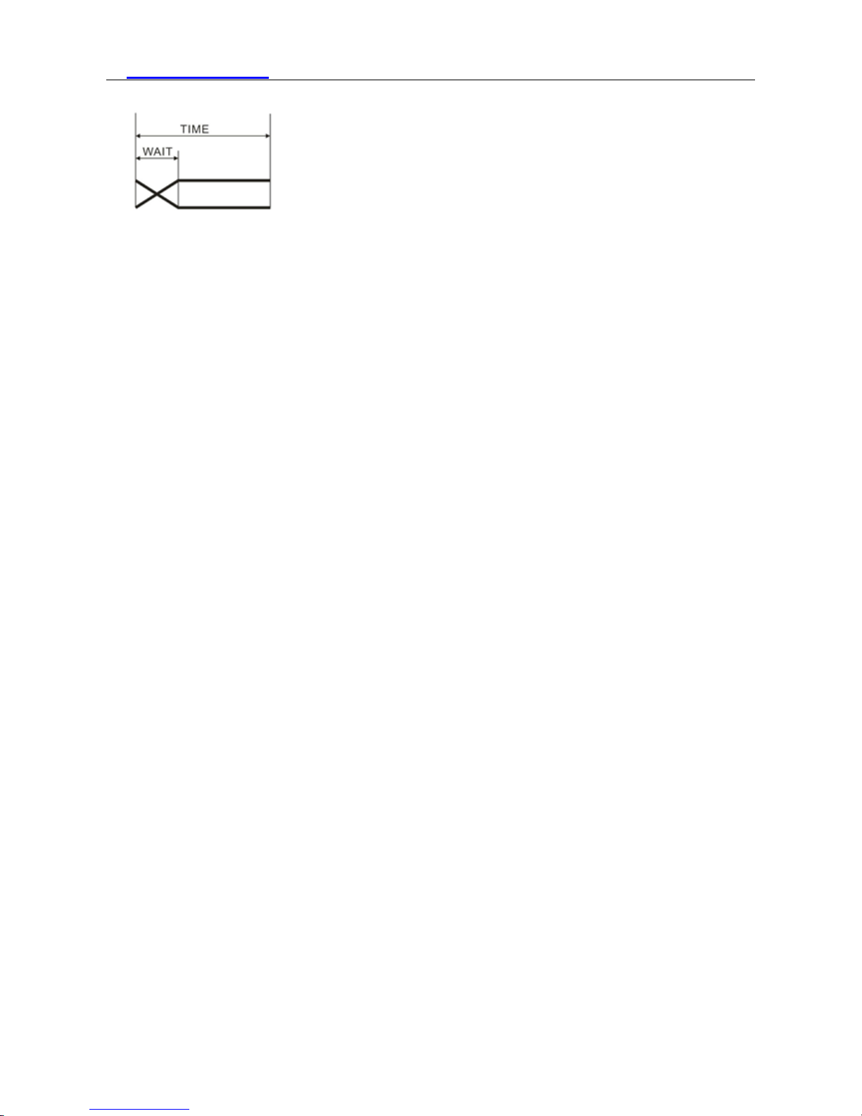
Illustrations:When【USE】 is set to be【NO】, or the parameter of【TIME】 is 0, it will not run this scene.When
【WAIT】is set to be FADE time, the running process isas the following chart showing.
www.lc-group.ca
12
6.11 CHECK THE LIGHTING INFORMA TION
1) Press the【ENTER】button in【INFO】menu, then enter to the checking the lighting information.
2
) 【
SOFT】button is for software version information.
3
) 【PO
W】button is for the current information of power reduction. It is 100% output in normal conditions, but
80% or 50% output in over temperature protection situation.
6.12 LIGHTING SETTING PARAMETER RESET
1) Press the【ENTER】button in【ST L】menu, then enter to the lighting setting parameter reset.
2
) P
ress the【UP/DOWN】button to select【YES】.
3
) P
ress the【ENTER】button to escape and save.
Illustrations: “ADDR” “CTST” and “PROG” are not reset, the others reset to the underlined value of the word.
6.13 【PROG】SELF-PROGRAMMING PARAMETER RESET
1) Press the【ENTER】button in【PR L】menu, then enter to the【PROG】self-programming parameter reset.
2
) P
ress the【UP/DOWN】button to select【YES】.
3
) P
ress the【ENTER】button to escape and save.
6.14 LIGHTING PARAMETER DOWNLOADING EACH OTHER VIA DMX
CABLE
1) Press the【ENTER】button in【SEND】menu, then enter to sending parameter to other lightings.
2
) P
ress the【UP/DOWN】button to select【YES】.
3
) P
ress the【ENTER】button to confirm sending.
Illustrations:
1)Please disconnect the connection of projector and DMX console before sending the parameter.
2)The information of【ADDR】、【CAL】can’t be sent, can’t be downloaded each other.
3)There will be an automatic reset of the other projectors after receiving parameter correctly.
www.lc-group.ca
13
7. Operating Control Instruction
Master/Slave
When the fixtures work in master mode it will send out the signal for the slave synchronous
with it. To avoid the host signal and DMX512 signals interfere with each other, should cut off the
DMX512 signals. The signal lines are longer than 60 meters (20 lamps), should increase a signal
amplifier.
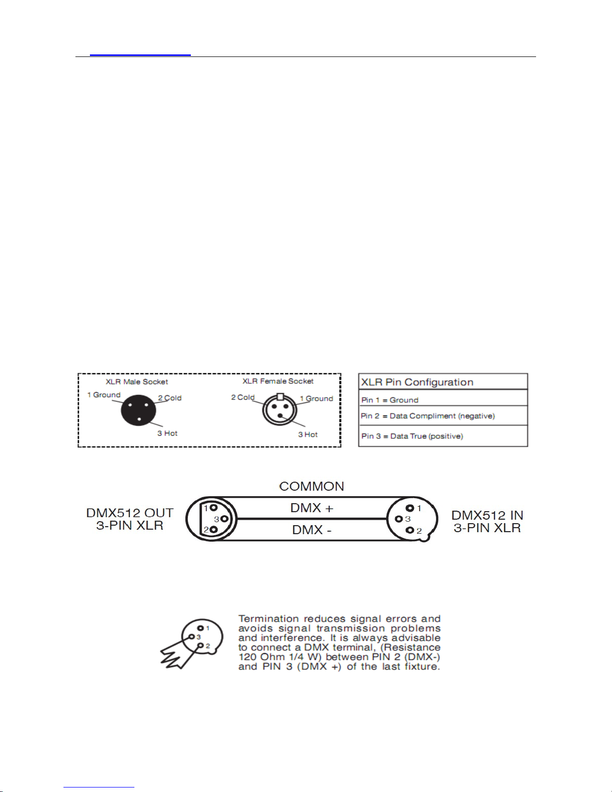
8. XLR cable connecting
XLR cable:
The standard connection way of the XLR is: one end connects to the male plug, and the other
connects to the female. As below: pin 1: ground, pin 2: negative signal, pin 3: positive signal
Noted:In order to avoid failures and interference signal transmission,we connect a
resistance120Ω ( 1/4W ) at the end of the DMX connecting as below:
The Conversion between 3 pin and 5 pin XLR
If the output cable of DMX512 controller is the 5PIN, please use 1pc 5PIN to 3PIN cable

www.lc-group.ca
14
9. Connecting picture
Light connecting picture:

www.lc-group.ca
15
10. Trouble Shooting
PROBLEM REASON AND ACTION
The lightin g can’t be
started normally
Check the power connection is correct or not.
Please detect the voltage.
Power supply is damaged or incorrect connected. Call a
qualified personnel to fix it.
Connection of control board is not correct.
Call a qualified
personnel to fix it.
Out of console’s
control
Please check the DMX connector and the power connection
is connected correctly or not. It means ha ving signal if it show s
twinkling of the decimal point which in the lower right corner
of the screen when exiting the screen saver.
Please check the DMX address setting of lighting is correct or
not.
Check【CHMD】setting is correct or not.
Please check whether the DMX line is near to the high v oltage
wire or not. In that case, it will damage or interf ere the DMX
electric circuit.
The beam appears
dim ,the brightness
declines obviously
Check whet
her the 【CAL】is started or not and the set value is
too small.
Check whether the【POW】
is in over temperature protection
situation or not, if yes, please take measures for ventilation.

www.lc-group.ca
16
 Loading...