


ic audio
Status 11/2009
User Manual
… to make people listen
Audio Matrix EV-5000

ic audio
EV-5000
EN
2
ic audio
1. Images
Front View
Rear View

ic audio
EV-5000
DE
3
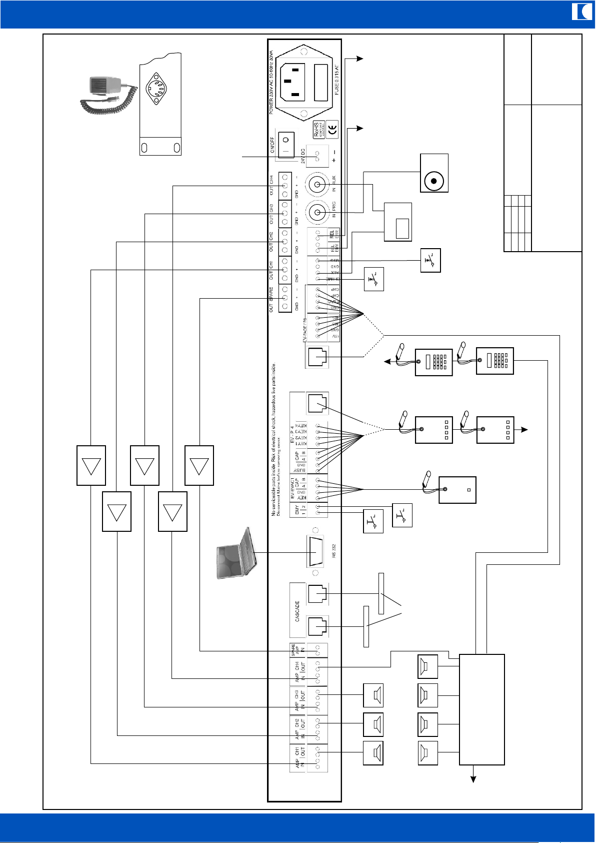
2. Block Diagram, System Overview
ic audio GmbH
D-68307 Mannheim
EV-5000 Block Diagram
2009
Draw
gfi
Mod.
26-10
Fire MIC1
80 CH MIC Bus
4 CH MIC Bus
BGM/Program IN
Inputs
MP3-Player
Digital Audio
Matrix
Power Amplifiers
Digital Control
Line Relays
Line Monitoring
EV-5000 Central Unit
CH1 OUT
CH2 OUT
CH3 OUT
CH4 OUT
SPARE AMP IN
OUT Spare Amp
OUT CH1
OUT CH2
OUT CH3
OUT CH4
2x Alarm Switch IN
Error
System
Emergency
Alarm
Relay contacts
Message
control IN
AUX IN
Request
230 V AC
~
=
24V DC Backup supply
Cascade RS 232
Fire MIC2
Matrix
Control
AMP IN
AMP IN
AMP IN
AMP IN
Chime
control IN
MIC control
AUX Request
ic audio
EV-5000
DE
4
alternatively alternatively
24V DC IN
EV-REL
Further
EV-PAGE
Further EV-P4
Spotplayer
Re-
quest
Audio
CD/
MP3
Relay contact active on
Fire-MIC announcement
or stored Emergency
announcement running.
Can be used to energize
priority override relays
Relay contact
active on any
errors
Background-
Music
Start Chime
(momentary switch)
Start stored message
(momentary switch)
Start stored
Emergency
announcement 1
Start stored
Emergency
announcement 2
EV-EVAC1
EV-P4
EV-P4
EV-PAGE
EV-PAGE
Further EV-5000
Personal Computer
for simple configuration
overview
Power Amplifiers
24V DC Backup-
Power IN
Fire MIC 1
Fire MIC 2 IN
on front panel
FIRE MIC
EV-5000
80-Channel MIC-Bus
OUT
IN
ic audio GmbH
D-68307 Mannheim
Overview EV-5000 System
2009
Draw
gfi
Mod.
26-10

ic audio
EV-5000
DE
5
1. Images 2
2. Block Diagram 3
System Overview 4
3. Table of Contents 5
4. Unpacking and verifying 6
5. Safety instructions 6
6. General Information 7
7. Key Features 8
8. System Components 9
9. Installation 10
10. Setting up the System 14
11. Programming the central unit EV-5000 14
12. Special Setups 18
13. Functions when connecting a PC 19
14. Deleting Error Messages 22
15. Priorities 23
16. Sound file card 23
17. EV-PAGE 80-Channel Callstation 25
18. EV-P4 Subzone Callstation 26
19. EV-EVAC 1 Fireman Desktop Microphone 26
20. EV-EVAC MIC Fireman Handheld Microphone 26
21. EV-REL Relay Card 27
22. Sample Setups 33
23. Technical Specifications 37
3. Table of Contents

ic audio
EV-5000
EN
6
4. Unpacking and verifying
Please verifiy if the following items were delivered:
n EV-5000
n Line cord
n All mating connectors for pluggable screw terminals
n User manual
5. Safety instructions
Please read carefully the instructions in this manual before use. Please keep this user manual
nearby for anytime reference.
The Audio Matrix EV-5000 is intended for use over a range of ambient temperatures from -5°C to
+55°C. During transport or storage temperatures from -20°C to +70°C are permissible. Do not
operate the EV-5000 in a damp or dusty area nor expose it to rain or to an environment, where it
may be splashed by water or other liquids. Please allow the unit sufficient time for acclimatisation
to room temperature (minimum 30 minutes) before powering up, if you bring it from a cold into a
warm environment. Do not place the product where it will be in the path of direct sunlight or near a
heater.
Check your local mains voltage before connecting the EV-5000. This device is normally set up for
an AC line voltage of 230 volts, 50 to 60 Hz.
The unit may only be operated at a power receptacle with protective earth conductor. The wires of
the mains power cord have the following colours:
GREEN and YELLOW: PE (Protective Earth)
BLUE: N (Neutral)
BROWN : L (Live)
Warning!
The protective earth conductor must never be interrupted even for test purposes! This may
be dangerous to life!
Do not block the ventilation slots of the chassis. This will cause the temperature rising and may
result in fire. Disconnect the power cord before removing the cover.
As the colours of the wires in the mains lead of this apparatus may not correspond with the
coloured markings identifying the terminals in your plug, proceed as follows:
The wire, which is coloured green and yellow, must be connected to the terminal which is marked
by the letter PE or by the safety earth symbol or coloured green and yellow. The wire, which is
coloured blue, must be connected to the terminal which is marked with the letter N or coloured
black. The wire which is coloured brown must be connected to the terminal which is marked with
the letter L or coloured red. The fuse protection in the house distribution may not exceed
16 Amperes.

ic audio
EV-5000
EN
7
If the following circumstances will occur, please immediately switch off the power and
disconnect the power supply cord. Do not try to operate the device again. Contact your
local dealer to check the unit:
n damages are visible
n the device has fallen
n the device contains loose parts or any liquid gets into the unit
n the device shows malfunctions
n smoke or strange smell is coming out of the device
n the power supply cord is damaged, such as exposure of the core, disconnection etc.
n the device has been stored for a longer period under bad conditions such as open air or in damp
rooms
n the device has been exposed to hard transport conditions like badly packing
When repairing devices with microprocessors (EV-5000, EV-PAGE and EV-REL), the general
precautions and actions reagarding electrostatic discharge have to be taken.
This appliance may only be used in accordance with its intended purpose: Audio Matrix in a public
address or voice alarm system.
6. General Information
The EV-5000 is a Public Address and Voice-Alarm Matrix, which operates all necessary
supervisionfunctions in a slim 1 unit housing according to EN 60849. You can connect several
callstations and release emergency-announcements, stored evacuation-signals, chimes and
background muisc.
All sound files are stored on a SD Flash Memory card for easy handling.
The EV-5000 is the smart choice for a wide range of applications such as schools, convenience
stores, factories, office buildings or hotels. In the minimal setup the system is working cost-effective
with only 1 main-amplifier and a backup-amplifier. In this mode it is possible to implement 4 paging
zones. It is possible to realise projects with additional relay-boards due to its 4 line outputs, or if
even more zones are required, up to 10 EV-5000 can be linked together to control up to 80
speaker zones.
The EV-5000 detects all connected components by an automatic set-up run. The identified items
are clearly shown on the display and will then be supervised completely by the system.
According to the EN 60849 standard the following documentation must be available respectively
records have to be kept:
1. User Manual
2. System Documents
3. Operation Log
4. Maintenance Record Keeping
Please refer to the mentioned standard for further details.

ic audio
EV-5000
EN
8
7. Key Features
u Closed 1 unit rack housing
u Easy programming by push buttons and blue illumunated display
u Connection of four 100V power amplifiers and one backup amplifier both supervised
u Each zone output is supervised for open line, short circuit, impedance deviation and short to
earth
u 4 transformer balanced line outputs to drive four power amplifiers
u Each line output has ist own volume, treble and bass controls
u Transformer balanced audio output to drive a backup amplifier
u Connection of up to 30 subzone EV-P4 callstations or up to 8 EV-PAGE callstations, so
80 zones can be realised
u Programmable preannouncement chime
u Connection of 2 Fireman callstations, one on rearside and one on front panel, Mic capsules
and control wires are monitored.
u 1 Line input (for instance for background music) with separate level control for each output
u 1 Line input (AUX) with contact activating for instance for spotplayer with separate level control
for each output
u 2 supervised emergency announcements (EMY) with contact activating
u 1 stored message (MSG) for instance for shop closing announcement
u Chime for breaks
u 230V AC or 24V DC operation
u Relay contact for signalling errors
u Relay contact to control priority override relays, which is active on calls from fireman MICs,
when playing an emergency announcement and during the automatic setup run
u Up to 10 units cascadable in a master/slave configuration. Master/slave predefinition by setting
several jumpers.
u Low cost zone expansion (without background music) by relay card

ic audio
EV-5000
EN
9
8. System components
8.1 EV-5000
Central unit, configurable as master or slave device by setting internal jumpers
8.2 EV-PAGE
System callstation to address up to 80 zones, emergency announcement (EMY1) can be started
8.3 EV-P4
Subzone callstation to address up to 4 zones
8.4 EV-EVAC 1
Fireman desktop microphone, monitored, 1x all call
8.5 EV-EVAC MIC
Fireman handheld MIC, monitored, 1x all call
8.6 EV-REL
Relay card for zone expansion

ic audio
EV-5000
EN
10
9. Installation
– see overview page 4 –
9.1 Power Supply
The device is designed for use with 230V AC 50 to 60 Hz mains power. Power can be switched
ON/OFF by the rear side mains power rocker switch.
A backup power providing 24V DC can be connected via a 2-pole pluggable screw terminal. The
rocker switch only breaks the mains power, not the 24V backup power. Both power sources are
monitored by the system. If during the installation run there is no backup power source connected,
the presence of the 24V DC power source is not supervised. Powering from a 24V DC source only
is not possible, since the system will generate always an error message as soon as mains power
fails, regardless what the state was during the installation run.
9.2 Connection of Power Amplifiers
Amplfier inputs have to be connected to the OUT CH1...OUT CH4 pluggable screw terminals, the
backup amplfier to the OUT SPARE connections. All outputs of the EV-5000 are transformer
coupled (balanced and floating) for trouble free operation. Therefore the cable shields have to be
connected at one end only. The following drawing shows some wiring for balanced and unbalanced
amplifier inputs:
These samples are valid for amplifiers, which are earthed by a 3-pole mains power cord and plug.
If all-insulated (double isolation, 2-pole mains power plug) amplfiers are used, which have also no
GND connection via a backup power supply, the shield must be connected on the EV-5000 side
(GND screw terminal) too.
The amplifier outputs (100V types only) are to be connected to the AMP IN1...AMP IN4 inputs and
SPARE AMP IN input respectively.
9.3 Connecting Speaker Lines
Speaker Lines are to be connected to the CH1 OUT...CH4 OUT terminals.
CAUTION!
For error free functioning of supervision, the minimum load has to be 10 Watts per zone at 22 kHz.
Please be aware that speaker impedances are frequency dependent, so each line has to draw
10 watts at 22 kHz not at 1 kHz. If it would be less, please connect a resistor 1 Kiloohm/10Watts in
parallel to the last speaker on the line. Maximum power must not exceed 800Watts/100V per zone.
GND + – GND + –
EV-5000 Isolate shield
2
3
1
Shield
Shield
Isolate shield
Isolate Ring or connect it with GND
GND Ring Tip
GND Ring Tip
Shield
Amplifier input XLR, bal.
Amplifier input
6.35mm Jack, bal.
Amplfier input
6.35mm Jack unbal.
Amplifier input
Cinch unbal.
GND + –
GND + –
Isolate shield
Isolate shield
Shield

ic audio
EV-5000
EN
11
9.4 Connecting Call Stations
The fireman call stations can be connected to the rear side pluggable screw terminals (EV-EVAC1,
Fire Mic1) or to the front side DIN connector (5-pole, 180°, Fire Mic2) for EV-EVAC MIC. Pin layout
is as follows:
Pins 1 + 3 = MIC capsule
Pins 4 + 5 = switch input (PTT)
Pin 2 = GND, shield
The subzone call stations EV-P4 are to be connected to the so designated pluggable screw
terminals or to the RJ45 connector. Up to about 30 EV-P4 can be connected in parallel. The RJ45
connectors pin layout is the same as the screw terminals:
1 = BUSY
2 = GND
3 = Capsule (CAP) hot
4 = Capsule (CAP) cold
5 = Key1
6 = Key2
7 = Key3
8 = Key4
The cable length with EV-EVAC1 and EV-P4 can be extended up to maximum 500 Meters. Of
course only well screened and twisted pair cable has to be used such as communications
installation cable F/UTP 4x2x0.8mm or CAT5/6. Due to analog signal type, there will be a high
frequency cut when extending cable length to more than about 200 Meters.
The EV-PAGE call stations (80 channel) are to be connected as well to pluggable screw terminals
as to a RJ45 connector. Up to 8 EV-PAGE can be connected in parallel. The RJ45 pin layout is
also the same as the screw terminals:
1 = +15V DC
2 = GND (0V[15V])
3 = RS485 +
4 = RS 485 –
5 = GND
6 = EVAC
7 = Capsule (CAP) hot
8 = Capsule (CAP) cold
Maximum cable run is 200 Meters. Only well shielded twisted pair telecommunications cable may
be used such as F/UTP 4x2x0.8 or CAT5/6. It is possible to extend the cable run up to 500 Meters,
if the DC power supply (normally 15V DC) will not drop below 14V at any call station. If so, please
add further pairs of wire in parallel to the supply leads. Here is also valid: cable runs with more than
about 200 Meters will cause a high frequency loss.
9.5 Connecting Program/Background music sources and AUX with request contact
The IN PRG cinch connector is the input for program/background music. Line sources with a 0 dBu
(=0.775B RMS) level are to be connected.
The AUX cinch connector is for line sources providing a dry contact for request such as a
spotplayer for instance. Line level has to be 0.775V RMS too. The contact must be wired to AUX
screw terminal and GND.
9.6 Further Control Inputs
To start stored alarm messages (for instance evacuation) the screw terminals EMY1 and EMY2
(against GND) can be used. The message is running as long as the control input is shorted to
GND. All wiring is monitored, this is why 2 resistors have to be added to a switch as shown below:
1
4
2
5
3

ic audio
EV-5000
EN
12
The chime (for breaks) and a stored message (for instance shop closing announcement) can be
started by an external control key (normally open, NO). The corresponding screw terminals are
designated CHIME and MSG (message). They have to be wired against GND. These control inputs
are not supervised and therefore no resistors are necessary.
9.7 Relay Contacts EMY and ERR
The dry contact designated EMY (emergency, normally open, NO) is active during an
announcement via a fireman call station or during a stored alarm anouncement (evacuation) run.
The EMY dry contacts are useful for energising priority override relays for instance. Furthermore
this contact is active on the installation run.
An ERR called dry contact (Error, normally open, NO) is active on all error messages from the
system. This is intended to control indicator lamps for instance.
9.8 Cascading, Master/Slave Operation
If the amount of zones is not adequate, Master/Slave systems can be configured. Up to 10 units
(1 Master and up to 9 Slaves) can be cscaded by 2 RJ45 connectors (CASCADE) in each unit for
simple looping in.
CAUTION!
Each unit (Master and Slave) must have its own backup amplifier. The backup amps ouput
power must be the same as the most powerful operational amplifier.
All EV-PAGE callstations are to be connected only to the master unit and not to any slave.
However the EV-P4 callstations can be connected to both Master and Slave units and will call to
zones connected to each unit only. It is not possible to make calls via EV-P4 from Slave to Master,
from Slave to Slave or vice versa. Of course EV-PAGE can call in all zones.
If AUX-input, Message and Chime (for breaks) should be started in all systems at a time, the
control contacts and the AUX audio signal inputs have to be paralleled. For activating stored
emergency announcements in Slaves, a separate alarm switch (with resistors for monitoring) has
to be installed each. As an alarm announcement is started in a Master unit, the Slaves will start as
well in zones and with levels as programmed in the particular Slave unit and with sound files as
recorded on their SD-card.
All error messages coming from Slaves will be shown globally in the Master unit as „SLAVE
SYSTEM“ and in the respective Slave with there detected details. Errors coming from a Master unit
will not be shown in Slaves.
The maximum length of the interconnection cable is limited on a few meters only, that is to say all
units have to be mounted into the same rack.
Each unit can be configured as Master and Slave by setting internal jumpers. If one unit only is
used, it has to be jumpered as a Master. Please find below two images, which show Master and
Slave configuration. The yellow arrows point at jumpers to be set, whereas the yellow rectangles
indicate pins which will stay open.
Alarm switch box
EV-5000
Line
EMY1 / 2
GND
4K7 4K7

ic audio
EV-5000
EN
13
Master:
Slave:
9.9 Display Language in EV-5000
Language can be altered by exchanging the 93C86 EEPROM (on socket, see stripy IC on Slave
image). Language EEPROMs are available from ic-audio.
9.10 Port for Personal Computer
A RS232 port is provided to connect a PC. For getting started no PC is necessary, but it will
provide for a quick and comfortable overview of all parameters and helps keeping records.

ic audio
EV-5000
EN
14
10. Setting up the System
After having assembled all components ready for use, the input sensivity of all power amplifiers
have to be adjusted to 0 dBU (= 0.775V RMS) for 100V of output voltage. The deviation of this
must not exceed ± 3 dB, that is to say the input sensivity has to be within 549 to 1095 Millivolts
RMS for 100V of output voltage.
Very Important!
After that, the installation run has to be started under full operational condition of all
components ( = all wiring completed, all power switches ON) in the system as follows:
Press the PROGRAM key
Press Key T3
Enter password = 3x pressing PROGRAM key consecutively
Press again key T3
As to be seen in the display, the installation run will start. If Slave units are present, these devices
will start their installation run at the same time, but the run can also be started separately for each
Slave in the same way. All connected components will be detected, shown in the display of the
central unit and installed.
After accomplishing the installation process, the following components are supervised:
EV-EVAC1, EV-EVAC MIC, the EV-PAGE cables in case of allocated address, alarm control
switches, power amplifiers, speaker lines, mains- and battery voltage.
If for instance an amplifiers fails, within 100 seconds there will be an acoustical warning (buzzer,
siren) and the error is indicated in the display. The backup amplifier will automatically be switched
in place of the defective operational amplifier – both input and output.
When not starting the installation run, no monitoring will take place and some of the system
components will not function.
To stop sounding the siren press the PROGRAM key, then key T2 (reset) and after that key T1
(= siren OFF). After having repaired the defective amplifier, a reset has to be made. In order to do
so, press the PROGRAM key again, then key T2 and once again T2 (LINE RLAYS). The error will
be resetted, the before faulty amplifier will be switched back to normal operation.
11. Programming the central unit EV-5000
When switching ON the unit, the version number is shown
in the display for a short time,
then the following screen appears:
This means on LINE1 (zone1) background music is switched ON
and the system works without any errors = OK.
11.1 User adjustable parameters
By pressing key T1 to T4 the background music status is indicated. If after the LINE-colon only
space characters are to be seen, background music for that zone is switched OFF.
The following user definable volume levels can be adjusted by the VOL key:
Music
Music MA (music master)
Chime
Message
AUX
By means of the UP / DOWN keys all volumes are to be modified. If the display shows something
like - - , the related sound source is switched OFF. The switch OFF function is only available in the
so called programming menu (described later) and thus not to be altered by a user. When for a
certain amount of time no key is operated, the display will fall back automatically to the opening
menu.
V1.0E 21.04.09
LINE 1 :MUSIC
SYSTEM: OK EV5000

ic audio
EV-5000
EN
15
After pressing the PROGRAM key the display shows:
Key1 opens the following sub menu:
With key T1 actual errors were shown,
with key T2 the previous errors.
Key2 brings to the following sub menu:
with key1 the siren (buzzer) can be stopped. If a new
error will occur, it will continue to sound.
With key2 all activated zone relays were resetted.
Key4 starts display of the MP3 card sound files
Finally with key3 the non user accessible programming menu opens.
11.2 Functions to be adjusted by the installer
Pressing key T3 will prompt for a password.
The password is:
press 3 times one after another the PROGRAM key
After successful login, the following screen appears:
n T1 goes to the sub menu for adjustment of the functions of preannouncement chime,
short to earth, impedance, short circuit, open line, alarm start, impedance tolerance,
measuring mode.
n T2 volume adjustment
n T3 installing all connected components – installation run
n T4 programming the audio outputs going to amplifiers and the line relays
T1 selects a sub menu, the display shows:
By pressing key T2 the preannouncement
chime can be switched ON and OFF
After pressing T1, on the display appears:
After pressing T2 appears:
By pressing T3 the zones can be selected and by
T4 measuring short to earth will be activated or
deactivated. Fallback to the previous item by pressing
the PROGRAM key.
Pressing T1 again on the display appears:
By pressing T2 measuring of impedance deviation
can be switched ON/OFF for each individual zone.
Handling is the same as described in the previous item.
T1=ERROR T2=RESET
T3=PROG. T4=MP3 CARD
T1=ACTUAL ERRORS
T2=PREV. ERRORS
T1=SIREN OFF
T2=LINE RELAYS
PASSWORD ???
V1.0E 21.04.09
T1=NEXT T2=LEVEL
T3=INST. T4=MOD/REL
T2=CHIME ON
T1=NEXT
T2 = SHORT TO EARTH
T1=NEXT
T3=CHOICE T4=SET/CLR
|4|3|2|1|
T2 = IMPEDANCE
T1=NEXT

ic audio
EV-5000
EN
16
Pressing T1 once again apears:
By pushing button T2 measuring of short circuit for
each individual zone will be activated or deactivated.
Handling is the same as described in the previous items.
Pressing T1 again apears:
By pressing key T2 measuring of open line for each
individual zone will be activated or deactivated.
Handling is the same as described in the previous items.
Pressing T1 once again appears:
Pushing T2 selects the kind of control for starting
the stored ermergency announcenments. In the
first case switch input 1 (EMY1) controls emergency
announcement 1 and switch input 2 (EMY2)
emergency announcement 2. In the second case both switch inputs will control
emergency announcement 1. Pressing T2 will toggle between the two modes.
Pressing T1 again appears:
Pushing button T2 several times will toggle
between normal and small tolerance of impedance
measuring.
Pressing T1 once agin appears:
T1 switches the AUX input (without using the
request control line) permanently active. This
function is very useful for testing voice
intelligibility. To stop this mode push the PROGRAM
key, whereon the system returns to the
opening menu.
T2 switches back directly to the opening menu.
T2 Adjustment of all volume controls
Besides the items shown in the users menu
MUSIC
MUSIC MA (music master)
CHIME
MESSAGE
AUX
now there are the following further controls to be adjusted:
VOLUME Master Volume control outputs
BASS Bass control outputs
TREBLE Treble control outputs
EV-P4 Volume control subzone callstations
EV-PAGE Volume control 80-channel callstations
ALARM1 Volume control stored emergency announcement 1
ALARM2 Volume control stored emergency announcement 2
FIRE MIC Volume control fireman MICs
T2 = SHORT CIRCUIT
T1=NEXT
T2 = OPEN LINE
T1=NEXT
T2 = ALARM START
SWITCH1-2 = ALARM1-2
T2 = ALARM START
ALL SWITCHES ALARM1
T2 = IMP. TOLERANCE
NORMAL
T2 = IMP. TOLERANCE
SMALL
MEASURING
T1=START T2=NEXT
MEASURING 1234
PROGR. KEY: STOP

The procedure is the same as on the users menu, but the password has to be entered first
and the items not available in the users menu can be adjusted here in the installers menu.
This covers also complete switch OFF of sound sources. All adjustments have to be done
separately for all 4 line outputs.
T3 Installation Run
After pressing T3 the installation run is executed. All connected operational components of
the system will be detected and installed. The parts of the system to be supervised are then
permanently checked for malfunction.
T4 Programming audio outputs and line relays
After pushing T4, the following display will appear:
Pressing T2 generates the following screen for
programming 80-channel callstations:
For pressing T1 (Alarm1, Alarm2, Message [MSG],
Chime, AUX, Fire MIC) and T3 (sub zone callstations
EV-P4) the same procedure is effective.
By pressing T1 the call key number will be raised,
GC (= group call), zone 01, 02, 03,...and so on.
By T3 the related audio outputs were selected and
by T4 the line relays.
Pressing T3 thereafter the following screen will appear:
This means here that all 4 audio outputs to amplifiers
will be activated. By T3 single outputs were selected
and T4 will set or clear them.
Pressing T4 the following screen appears:
Here it is defined, which of the 4 line relays are
activated.
Caution!
In a standard configuration as shown on page 4, the line relays have to be cleared – no
numbers set. This will continue backgroundmusic on the not adressed zones during an
announcement.
In the following special examples 12.1 and 12.2, programming has to be done different
according to the requirements of these configurations. Because of supervision, here
the line relays have to be programmed inverse, that is to say in zones, in which a call
should go, the relays stay not energised. In zones, where the call should not be
heard, the relays will be energised and so switch these zones OFF. For programming
line relays this means, that always relays have to be activated, which have to switch
OFF zones. In the screen shown above the call will sound in all 4 zones.
By programming each single key of the callstations individually with audio and relay
switch functions, it is possible to generate single call and any combination of zones for
group calls and all call. When using EV-REL relay cards, those have to be programmed
additionally by means of their DIP-switches – see chapter 21 EV-REL.
The subzone callstations EV-P4 cannot be used together with EV-REL relay
cards.
Pressing the PROGRAM key will always return to the previous menu.
ic audio
EV-5000
EN
17
T1=TEXT/AUX/ALARM
T2=EV-PAGE T3=EV-P4
KEY NR:GC T1=NEXT
T3=AUDIO T4=RELAYS
T3=CHOICE T4=SET/CLR
|4|3|2|1|
T3=CHOICE T4=SET/CLR
| | | | |
ic audio
EV-5000
EN
18
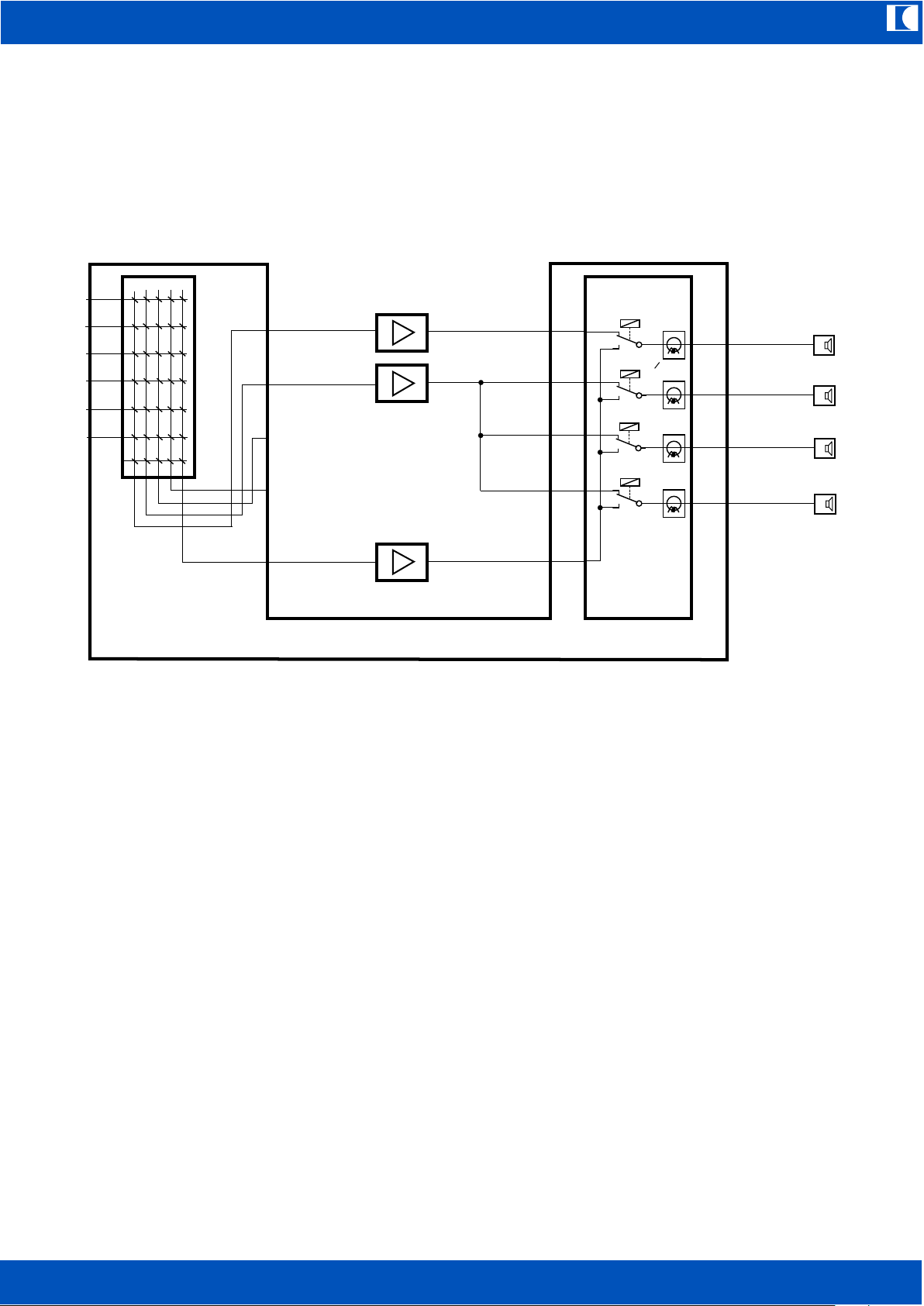
12. Special Setups
12.1 Sample configuration with one amplifier driving 3 zones
In this sample two operational and one backup (spare) amplifier are applied. Please keep in mind,
if a call goes to zone 2,3 or 4 the background music will be stopped in all these zones. Of course
zone 1 will not be affected.
Programming for distributing a call in zone 3 for instance shall be executed as follows:
Activate audio on CH2, on all other channels audio has to be deactivated.
Energise relays 2 and 4 as a call goes to zone 3.
As already mentioned, relays have to be activated, which must switch OFF zones. In principle the
same is valid for emergency announcements or inhouse messages (MSG) for instance.
During a call, switched OFF zone speaker lines were connected to the backup amplifier by the line
relays. The backup amplifier provides for the check tone too, so that switched OFF zones are
monitored permanently.
Power Amplifiers
CH1 OUT
CH2 OUT
CH3 OUT
CH4 OUT
SPARE AMP IN
OUT Spare Amp
OUT CH1
OUT CH2
OUT CH3
OUT CH4
AMP IN
AMP IN
AMP IN
AMP IN
Spare Amplifier
Input
Matrix
Line Relays and
Monitoring

ic audio
EV-5000
EN
19
12.2 Sample configuration with several power amplifiers connected to one audio output
In the above sample several amplifiers are connected to one of the audio outputs
(OUT CH1...OUT CH4).
The system will of course detect only one joint amplifier, but the supervising functions will be
maintained. If one of the operational amplifiers fails, it will be replaced automatically by the backup
amplifier.
13. Functions when connecting a Personal Computer
With a PC it is possible to display comfortably all programming and adjustments without checking
all menus and submenus with the exception of item 5 and 7 below. Therefore no special software
is needed, a simple terminal software such as Windows Hyperterminal will do. First a PC COMport is to be connected to the RS232 port of the EV-5000 via a null-modem cable (reversed). Start
the terminal software and ajust the following parameters:
©
Bits per second 9600
Data bits 8
Parity none
Stop bits 1
Protocol none
To call for the function menu enter „i“ – without the quotation marks of course. The following screen
appears:
Power Amplifiers
CH1 OUT
CH2 OUT
CH3 OUT
CH4 OUT
SPARE AMP IN
OUT Spare Amp
OUT CH1
OUT CH2
OUT CH3
OUT CH4
AMP IN
AMP IN
AMP IN
AMP IN
Spare Amplifier
Input
Matrix
Line Relays and
Monitoring

ic audio
EV-5000
EN
20
The PC readouts in detail:
Key 1 Installed components
Key 2 Audio level
EV5000
KEY 1 : installed components
KEY 2 : Audio level
KEY 3 : Audio and Relaisprogramming
KEY 4 : Misc. Setting
KEY 5 : Text input
KEY 6 : Errors
KEY 7 : Factory Setting
Caution !! Delets all Settings
INSTALLED COMPONENTS
ALARM 1 3.3V
ALARM 2 3.3V
FIRE MIC1 3,4V COIL :INSTALLED
FIRE MIC2 3,3V COIL :INSTALLED
PAGE/P8 2 3
AMP: 1 LINE : 1 :030 032
AMP: 2 LINE : 2 :038 035
AMP: 3 LINE : 3 :036 033
AMP: 4 LINE : 4 :035 036
SPARE AMP INSTALLED
BATT.VOLTAGE :24V
LEVEL ZONE1 ZONE2 ZONE3 ZONE4
MUSIC |-06 dB |-06 dB |-06 dB |-06 dB |
MUSIC MA |-12 dB |-12 dB |-12 dB |-12 dB |
CHIME |-16 dB |-16 dB |-16 dB |-16 dB |
MESSAGE |-06 dB |-06 dB |-06 dB |-06 dB |
AUX |-06 dB |-06 dB |-06 dB |-06 dB |
VOLUME | 10 dB | 10 dB | 10 dB | 10 dB |
BASS | 00 dB | 00 dB | 00 dB | 00 dB |
TREBLE | 00 dB | 00 dB | 00 dB | 00 dB |
EV-P2/4 |-06 dB |-06 dB |-06 dB |-06 dB |
PAGE/P8 |-06 dB |-06 dB |-06 dB |-06 dB |
ALARM 1 |-06 dB |-06 dB |-06 dB |-06 dB |
ALARM 2 |-06 dB |-06 dB |-06 dB |-06 dB |
FIRE MIC |-06 dB |-06 dB |-06 dB |-06 dB |

ic audio
EV-5000
EN
21
Key 3 Audio and Relay Programming
It must be pointed out, that sources which are not allocated to a zone and have no line relay
activated, will not be shown in that screen.
Key 4 Miscellaneous Settings
Key 5 Text Input
After entering a key number and changing the label ZONE 1 (12 characters maximum) for instance
the following appears:
SOURCE |L1|L2|L3|L4| |R1|R2|R3|R4|
EV-P2/4 01|**| | | | | | | | |
EV-P2/4 02| |**| | | | | | | |
EV-P2/4 03| | |**| | | | | | |
EV-P2/4 04| | | |**| | | | | |
ALARM 1 |**|**|**|**| | | | | |
ALARM 2 |**|**|**|**| | | | | |
MESSAGE |**|**|**|**| | | | | |
CHIME |**|**|**|**| | | | | |
AUX |**|**|**|**| | | | | |
FIRE MIC1 |**|**|**|**| | | | | |
FIRE MIC2 |**|**|**|**| | | | | |
PAGE/P8 GC|**|**|**|**| |**|**| | |
PAGE/P8 01|**| | | | | |**|**|**|
PAGE/P8 02| |**| | | |**| |**|**|
PAGE/P8 03| | |**| | |**|**| |**|
PAGE/P8 04| | |**| | |**|**|**| |
CHIME ON
MUSIC ON
SHORT TO EARTH 4I3I2I1I
IMPEDANCE 4I3I2I1I
SHORT CIRCUIT 4I3I2I1I
OPEN LINE 4I3I2I1I
SWITCH1-4 = ALARM1-4
NORMAL 007
TEXT INPUT:
LINE 1 KEY 1
LINE 2 KEY 2
LINE 3 KEY 3
LINE 4 KEY 4
TEXT INPUT:
STOCK 1 KEY 1
LINE 2 KEY 2
LINE 3 KEY 3
LINE 4 KEY 4
TEXT INPUT: ...DONE

ic audio
EV-5000
EN
22
Any user defined sequence of characters can be entered, which is subsequently shown in the
EV-5000s display. Due to running supervising and measuring processes at the same time, may be
there is a few seconds delay, before the system will respond.
Key 6 Errors
Key 7 Factory Setting
After pushing key 7, first a confirmation dialogue appears:
Entering a Y (upper case !) and confirming by pressing the enter key, factory settings (delivery
status) were loaded. Alle user settings are deleted.
14. Deleting stored Error Messages
Please perform one of the following procedures to delete all stored error messages:
1. Start an installation run after entering the password.
or
2. Load factory settings. This can only be done by connecting a PC, starting the terminal software
and then pushing key 7.
LINE : 1 008 000 000 OK
LINE : 2 059 000 000 OK
LINE : 3 011 000 000 OK
LINE : 4 074 000 000 OK
SPARE AMP OK
FIRE MIC1 REQUEST OK COIL : OK
REQUEST ALARM 1 OK
REQUEST ALARM 2 OK
MP3 CARD OK
BATT.VOLTAGE : OK
EV-PAGE 2 OK
EV-PAGE 3 OK
ERASE ALL? Y=YES

ic audio
EV-5000
EN
23
15. Priorities
Each audio source is allocated to the following fixed priority levels – 1 = highest, 10 = lowest:
1. Fire MIC 1 = fireman MIC connected to rear side pluggable screw terminals
2. Fire MIC 2 = fireman MIC connected to front side DIN-connector
3. Emergency announcement 1 (EMY1)
4. Emergency announcement 2 (EMY2)
5. AUX with request
6. Message (MSG)
7. EV-PAGE 80 zone call station
8. EV-P4 sub zone callstation, 4 zones
9. Chime
10. Background music
Running lower priority sources like chime and EV-P4 do not initiate a busy status in the EV-PAGE
call station.
The EV-PAGE callstations among each other have block mode priority, that is to say the first
activated EV-PAGE in a system has priority, all others were busy and blocked.
EV-P4 callstations among each other have no priority. So if keys at two EV-P4 were pushed
simultaneously, both will be active. Please observe the busy signalling LED before pushing a call
key when using an EV-P4.
An active higher priority audio source will trigger busy status, which is indicated by a quickly
flashing busy LED in EV-P4 and by showing BUSY in the EV-PAGEs display.
An EV-P4 sub zone call station connected to a slave unit can make calls in its slave system at the
same time, as another EV-P4 on a master unit shall do. There is no interference one to another.
16. Soundfile Card
All sound files are stored on a SD-card inside the device. The system can play MP3 or wave sound
formats. For MP3 files a bit rate of 128 Kbit/s, sample frequency 44.1 kHz, Mono or more is
recommended, which will provide nearly CD sound quality.
The sequence of the files on the SD-card has to be absolutely maintained, since the system
accesses the files on the basis of the sequence:
1. 16 kHz test tone
2. Preannouncement chime
3. Emergency announcement 1
4. Emergency announcement 2
5. Message
6. Chime for breaks
In order to edit sound files, first the device has to be disconnected from all power supply, both
mains and 24V DC battery power. After removing the cover, the SD-card can be extracted and
inserted in a SD card slot of a computer.
Concerning the sequence, please be aware that most operating systems (Windows too) do not
show the true sequence. When copying files please proceed as follows:
©

ic audio
EV-5000
EN
24
1. Save file 1 = 16 kHz test tone – this file must be first and original file on the card
2. Delete all files on the SD card
3. 16 kHz test tone mark, copy and paste
4. Preannouncement chime mark, copy and paste
5. Emergency announcement 1 mark, copy and paste
6. Emergency announcement 2 mark, copy and paste
7. Message mark, copy and paste
8. Chime for breaks mark, copy and paste
After reinserting the SD card into the EV-5000, the sequence can be checked by pressing the
PROGRAM key and then T4. The file numbers and the file names are displayed one after another.
The file names may contain up to 8 characters.
The 16 kHz test tone has to be placed first and as original sound file on the card, it is stored also
first on the card on delivery.
Each of the 6 above mentioned storage places have to be recorded. If places are not used, store
empty sound files instead.
Sound files should have a 1 second pause at the beginning – with the exception of the test tone of
course.

ic audio
EV-5000
EN
25
17. EV-PAGE 80-Channel Call Station
The comfortable call station EV-PAGE can address up to 80 zones.
By means of a numeric keyboard and a display all functions can be
operated very comfortable.
Additional there are control keys for single call, group call and
all call as well as for programming and starting emergency
announcement 1.
Busy status is shown in the display as clear text and by a red
luminous ring on the gooseneck microphone.
The programming function – to be accessed via the PROGRAM
key – allows also for switching ON/OFF the background music,
labelling zones for indicating in the display and the allocation of an
address.
Pressing the PROGRAM key will show in the display:
Pressing key 1 will switch ON/OFF backgrond music for all zones
simultaneously. ON/OFF will toggle cyclically on each push.
By means of key 3 the first 44 zones can be labelled to be displayed
on the EV-PAGE:
That means:
Zone 01 is labelled ZONE.
By key 0 the next zone to be labelled can be selected.
By key PROGRAM the cursor is moved and by key ALARM the menu is left. When leaving, all
entries are stored automatically.
To enter texts, the numeric keys are multiple used, characters can be chosen by several pushing a
key:
Key 4 allows for allocating an address to the call station. Addresses can be selected in the range of
00 to 08. If 00 ist assigned, the ALARM key has no function, whereas the addresses 01 to 08 will
unblock the ALARM key for starting emergency announcement 1 (EMY1).
That is why this setting has to be adjusted by the installer only!
It has absolutely to be avoided to enter the same address double in a system. After modifying an
address, the so called installation run has to be started – see chapter 10. As the alarm start
function is then enabled, also the data lines of the EV-PAGE are monitored.
Procedure for allocating an address:
1. After pressing the PROGRAM key press and hold key 4.
2. Pess the PROGRAM key and hold it as well
3. Release key 4, then release key PROGRAM
After each key sequence, the address number will be increased by one:
00 - 01 - 02...08 - 00 - 01 and so on.
Key 1: A B C D ( = space)
Key 2: E F G H
Key 3: I J K L
Key 4: M N O P
Key 5: Q R S T
Key 6: U V W X
Key 7: Y Z . : =
Key 8: 0 1 2 3 4
Key 9: 5 6 7 8 9
1=MUSIC ON
3=TEXT 4=NR00
KEY 01 0=NEXT
ZONE

ic audio
EV-5000
EN
26
Start emergency announcement 1:
After pressing and holding the ALARM key, the display shows:
As the 5 seconds are elapsed, emergency announcement 1 will start and the display shows:
The alarm is now running – even without pressing the key – until it will
be stopped by the PROGRAM key. If the ALARM key is released before
the 5 seconds were elapsed, the emergency annoncement shall not be started.
18. EV-P4 Subzone Call Station
Subzone callstation for addressing up to 4 zones.
There are 4 calling buttons as well as a LED to indicate a busy
condition.
Programming zones has to be done in the EV-5000 central unit.
Any zones can be defined, also several on one button, all call included.
The busy LED gives notice, if the call station is ready to use.
Quickly flashing indicates that a preannouncement chime, an
emergency announcement or a message is just running as well as
another call station is active or the AUX input is requested. An active
fireman call station is indicated by continuous lighting.
The busy signalling has to be observed to avoid two persons talking
at a time, since the EV-P4 have no priority function among each other.
Of course in busy state coming from a higher priority sound source,
talking is blocked.
19. EV-EVAC 1 Fireman Desktop Microphone
Fireman desktop call station equipped with an all call key.
This call station has highest priority. The dynamic capsule and
the control leads are monitored.
20. EV-EVAC MIC Fireman Handheld Microphone
Fireman handheld microphone equipped with PTT-button
for all call. The handheld MIC has highest priority too.
The dynamic capsule and the control leads are monitored.
!!!CAUTION!!!
ALARM IN: 5 SEC
ALARM
KEY P = STOP
ic audio
EV-5000
EN
27
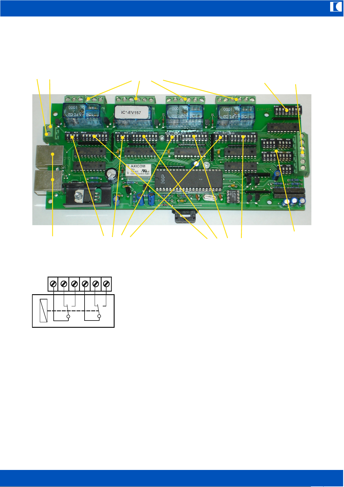
21. EV-REL Relay Card
Relay card for extending zones and for getting additional switch functions
Pin Layout of Relay Contacts:
C = Common
NC = Normally closed
NO = Normally open
All 4 relays have identical pin layout and each
provide for 2 changeover contacts.
The relay card EV-REL is an open board to be built in a housing or in a rack. A flange mounted
bracket allows for fast and easy fixing on mounting rails (DIN rail 35x7,5 or 35x15mm).
EV-REL provides 4 relays (R1...R4) with 2 dry changeover contacts each.
It can be controlled by the 80-channel MIC bus of a EV-5000 Master and/or 5 control contacts. For
easily inserting into a call station bus, 2 parallel RJ45 sockets are available.
Each relay can be programmed by means of DIP-switches. By switching speaker lines in inverse
mode, the supervising functions from Master/Slave units will be maintained.
Power has to be supplied by an external 24V DC source, for instance by a mains adaptor or by the
continuous output of a battery manager.
Please find below a block diagram EV-REL:
Relay contacts 4x2 changeover
Global decoder
80-channel bus
Supply voltage
0V +24V
Switch matrix 80-channel bus
Data decoder 80-channel bus
80-channel
MIC bus
Switch matrix
contact
Contact
inputs
R1
R2
R3 R4
NO
C CNC NC
NO

ic audio
EV-5000
EN
28
ic audio GmbH
D-68307 Mannheim
Block Diagram
EV-REL
2009
Draw
gfi
Mod.
02-07
ON
D8 D7 D6 D5 D4 D3 D2 D1
ON
R1 R2 R3 R4
ON
D8 D7 D6 D5 D4 D3 D2 D1
ON
ON
D8 D7 D6 D5 D4 D3 D2 D1
ON
ON
D8 D7 D6 D5 D4 D3 D2 D1
ON
ON
D8 D7 D6 D5 D4 D3 D2 D1
ON
ON
ONON
ON
DECODER 1DECODER 2
DECODER 3
DECODER 4DECODER GLOBAL
SWITCH-
MATRIX
SWITCH-
MATRIX
SWITCH-
MATRIX
SWITCH-
MATRIX
RELAYS 1 2 3 4
80 CH MIC-BUS
IN/OUT
T1
T2
T3
T4
PRIO
+
–
24V DC IN
SWITCH CONTACT
INPUTS
R1 R2 R3 R4
R1 R2 R3 R4
R1 R2 R3 R4
R1 R2 R3 R4
R1 R2 R3 R4
R1 R2 R3 R4
R1 R2 R3 R4
R1 R2 R3 R4

ic audio
EV-5000
EN
29
The device consists of the following functional units:
1. 4 decoder units, which accept commands from the 80-channel call station bus
4 DIP-switch blocks, which distribute the decoder outputs to the 4 relays
2. 5 DIP switch blocks, which handle the contact inputs also for EV-P4,
4x zones and 1x busy
3. 1 decoder for global commands, which control all 4 relays simultaneously
So there are 10 selectable switch functions, which can be allocated optional to each of the 4 relays.
Indeed one relay can be assigned to multiple switch functions, as well as one switch function can
control multiple relays at the same time.
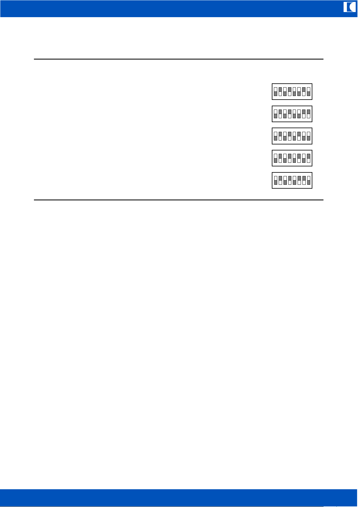
21.1 Application of EV-REL for extending zones
Data coming from the 80-channel bus are fed to 4 decoders, consisting of an 8-pole + 4-pole DIPswitch and an evaluation electronics. By the 8-pole DIP switches the binary address is defined, to
which each decoder will be sensitive to. The 4-pole DIP-switch distributes the decoders output to
the 4 relays. The following code table contains the binary codes for each available function –
D8...D5 most significant byte, D4...D1 least significant byte. So if a decoder should switch relays as
the message (MSG) is running, the following address is to be entered:
98H = 1001 1000 or
D8=1, D7=0, D6=0, D5=1, D4=1, D3=0, D2=0, D1=0
Thereby means 0 = DIP switch OFF and
1 = DIP switch ON.
The related 4-pole switch matrix will define the relays to be energised,
in the adjacent sample these are relays R1, R3 and R4.
As already explained, for inverse function of line relays control, the
not active lines have to be switched. So in this example the message will only be heard in the
zone, which is connected to relay 2.
Attention!
The global decoder has to be set to address AAH as the EV-REL is used for extending the
number of zones in inverse programming mode – see following list of codes. In the inverse
mode the global decoder can no longer be used for global functions.
The inverse mode will cause all relays to be energised on all cards, as soon as a call key is
pressed on the EV-PAGE. Single decoders take priority over the global decoder, in that way that
relays for programmed speaker lines remain not energised and so signals will be heard on just
these lines.
Furthermore the PRIO - input of the contact switch matrix has to be connected to GND.
This will change the PRIO 4-DIP-switch block into
a relay selector switch for group call (group call
key on EV-PAGE). The DIP-switches R1 to R4
below PRIO determine relays, which switch after
pressing the group call key. Here too inverse
programming has to be performed. In the adjacent
sample the call will go to lines connected to relay 1
and relay 3.
Switch inputs T1 to T4 cannot be used in
inverse mode (address AAH set at global
decoder)!
Hence EV-P4 call stations cannot be used
together with EV-REL relay cards.
Contact switch matrix
D8 D7 D6 D5 D4 D3 D2 D1
ON
ON
R1 R2 R3 R4
ON
R1 R2 R3 R4
ON
R1 R2 R3 R4
ON
R1 R2 R3 R4 ONR1 R2 R3 R4
ON
R1 R2 R3 R4
T1
T2
T3
T4
PRIO
T1
T2
T3
T4
PRIO
0V, GND
Wire link
for invers
mode

ic audio
EV-5000
EN
30
21.2 Application of EV-REL for getting additional switch functions
Besides using EV-REL in invers programming mode for extending zones, it can also be applied in
normal mode for getting additional switch functions.
Any switch functions can be implemented, for instance to trigger control lamps or priority override
relays, switching illuminations and so on.
The global decoder then can have the code lists second page addresses too (of course not the
AAH!). At the single decoders 1 to 4 – as in inverse mode – addresses from the subsequent list of
codes can be set as described before.
The global decoder has no switch matrix, its output will always energise all 4 relays at the same
time.
In addition to the 80 channel bus, in normal mode the inputs of the contact switch matrix T1 to T4
and PRIO can be used. These inputs can be connected to the switch outputs of the EV-P4
subzone call stations for instance. Each of the 5 inputs is to be routed via a 4-pole DIP-switch to
the 4 relays. The switch inputs have high level (+5V) when not activated and are to be connected
to GND for activation.
Sample:
If relay 2 should switch as input T4 will be
grounded, at DIP switch T4 R2 (relay 2)
is to be set to the ON position. All other
switches have to be set to the opposite
(OFF) position.
ON
R1 R2 R3 R4
ON
R1 R2 R3 R4
ON
R1 R2 R3 R4 ONR1 R2 R3 R4
ON
R1 R2 R3 R4
T1
T2
T3
T4
PRIO
T1
T2
T3
T4
PRIO
0V, GND
ic audio
EV-5000
EN
31
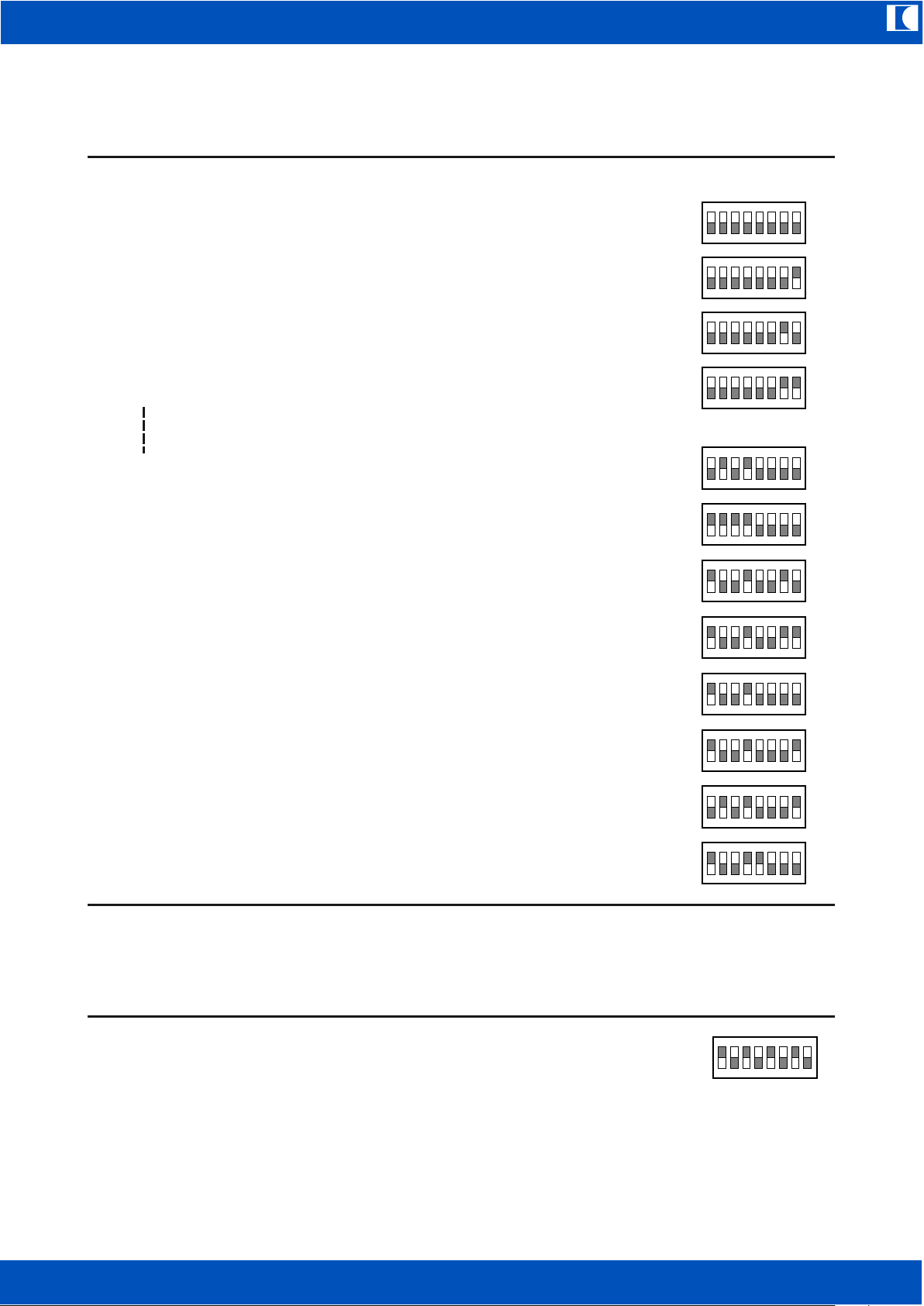
21.4 List of Codes for setting up Decoders
Function Dezimal Hex Code Binary Code DIP-Switch
Codes for decoders 1 - 4 only:
EV-PAGE Group Call 00 00H 0000 0000
EV-PAGE Zone 1 01 01H 0000 0001
EV-PAGE Zone 2 02 02H 0000 0010
EV-PAGE Zone 3 03 03H 0000 0011
(continuing to)
EV-PAGE Zone 80 80 50H 0101 0000
EV-PAGE All Call 240 F0H 1111 0000
Alarm 1 (EMY 1) 146 92H 1001 0010
Alarm 2 (EMY 2) 147 93H 1001 0011
Fire MIC 1 144 90H 1001 0000
(rear side of device)
Fire MIC 2 145 91H 1001 0001
(front side, DIN-connector)
AUX 81 51H 0101 0001
Message (MSG) 152 98H 1001 1000
Code for selecting inverse programming mode to supervise speaker lines – for global
decoder only:
Inverse Mode 170 AAH 1010 1010
Set this code at the global decoder for using EV-REL to extend the number of speaker lines in an
EV-5000 system.
ON
D8 D7 D6 D5 D4 D3 D2 D1
ON
D8 D7 D6 D5 D4 D3 D2 D1
ON
D8 D7 D6 D5 D4 D3 D2 D1
ON
D8 D7 D6 D5 D4 D3 D2 D1
ON
D8 D7 D6 D5 D4 D3 D2 D1
ON
D8 D7 D6 D5 D4 D3 D2 D1
ON
D8 D7 D6 D5 D4 D3 D2 D1
ON
D8 D7 D6 D5 D4 D3 D2 D1
ON
D8 D7 D6 D5 D4 D3 D2 D1
ON
D8 D7 D6 D5 D4 D3 D2 D1
ON
D8 D7 D6 D5 D4 D3 D2 D1
ON
D8 D7 D6 D5 D4 D3 D2 D1
ON
D8 D7 D6 D5 D4 D3 D2 D1
ic audio
EV-5000
EN
32
ON
D8 D7 D6 D5 D4 D3 D2 D1
ON
D8 D7 D6 D5 D4 D3 D2 D1
ON
D8 D7 D6 D5 D4 D3 D2 D1
ON
D8 D7 D6 D5 D4 D3 D2 D1
ON
D8 D7 D6 D5 D4 D3 D2 D1
Function Dezimal Hex Code Binary Code DIP-Switch
Codes for decoder 1 to 4 as well as for global decoder
EV-PAGE global, acts on
Single Call, Group Call and All all 82 52H 0101 0010
Alarm 1+2, Fire MIC 1+2 83 53H 0101 0011
Alarm 1+2 84 54H 0101 0100
Fire MIC 1+2 85 55H 0101 0101
EV-PAGE global, Fire MIC 1+2, 86 56H 0101 0110
Alarm 1+2

ic audio
EV-5000
EN
33
22. Sample Setups
22.1 Standard configuration
1 or 2 fireman callstation(s)
Up to 8 EV-PAGE with or without preannouncement chime
Up to 30 EV-P4 with or without preannouncement chime
2 stored emergency announcements
1 AUX-input with contact activating (request)
1 stored message
1 chime for breaks
1 program/backgroundmusic input
Maximum 4 zones without EV-REL relay card
EV-5000
EV-P4
RAC 02 CD/MP3
Background music
AMP 480
CH 1 OUT
CH 2 OUT
CH 3 OUT
CH 4 OUT
AMP 480
AMP 480
AMP 480
Audio in+
100V Line
Speaker line 1 (100V)
Speaker line 2 (100V)
Speaker line 3 (100V)
Speaker line 4 (100V)
Audio in+
100V Line
Audio in+
100V Line
Audio in+
100V Line
EV-PAGE EV-EVAC 1
EV-EVAC MIC
ic audio
EV-5000
EN
34
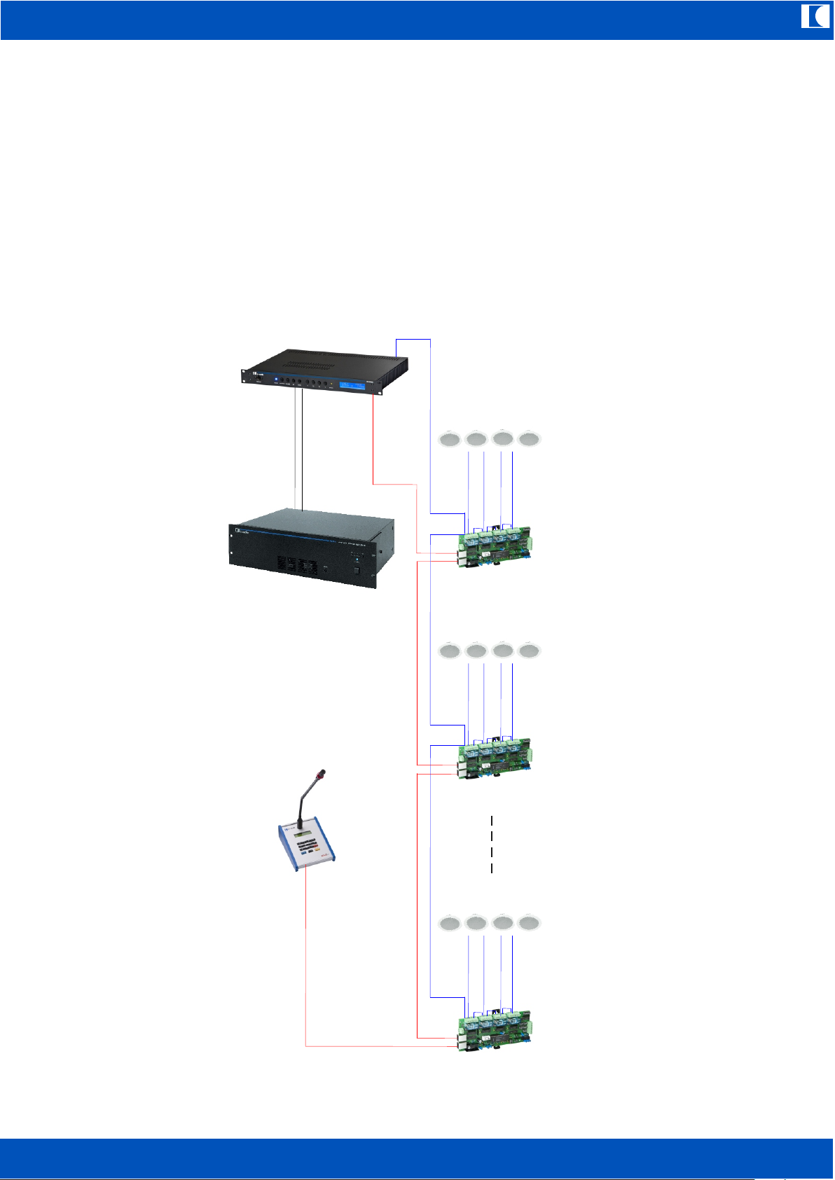
22.2 Expansion by means of relay cards
Adding up to 20 EV-REL maximum 80 zones can be addressed.
There are some limitations using relay cards: At all EV-REL connected to one 100V line output of
EV-5000, background music is switched off as soon as only one zone is addressed. The reason for
this is, that one amplifier cannot transmit two different signals (Call and BGM) at a time. Of course
this is not valid for the remaining three zones of the EV-5000, to which no EV-RELs are connected.
Attention should be paid to the fact, that EV-P4 subzone callstations will not work together with
EV-REL.
AMP 480
CH 1 OUT
EV-REL
Speaker Line 1-4
(100V)
100V Line Out
80 CH Bus
EV-REL
Speaker Line 5-8
(100V)
EV-REL
Speaker Line 77-80
(100V)
EV-PAGE

ic audio
EV-5000
EN
35
22.3 Expansion with one Master and up to 9 Slave units:
In that case up to (1+9)*4 = 40 zones can be established without using EV-REL. Background music
and calls can be transmitted individually per zone without interfering each other. Each Master and
each Slave unit must have its own backup (spare) amplifier.
For each Slave there are now additional functions and further accessories can be connected:
1 preannouncement chime individually switchable at Master and Slaves. So preannoucement
chime can be switched on at Master and switched off at Slaves or vice versa.
2 stored emergency announcements
1 AUX-input with contact activating (request)
1 stored message
1 chime for breaks
1 program/backgroundmusic input
The preceding additional Slave sources can only be used in the respective Slave unit. They cannot
be routed to another Slave or to the Master unit.
Up to 30 EV-P4 per Slave, the Master can have also up to 30 EV-P4 simultaneously.
EV-PAGE and EV-EVAC have to be connected to the Master unit only.
AMP 480
EV-5000
Master
EV-EVAC 1
CH 1 OUT
Backup amplifier
EV-PAGE
NF+
100V Linie
Speaker line 1 (100V)
Speaker line 2 (100V)
Speaker line 3 (100V)
AMP 480
CH 4 OUT
AMP 480
CH 2 OUT
AMP 480
CH 3 OUT
Speaker line 4 (100V)
NF+
100V Linie
NF+
100V Linie
100V Line Out
Cascade
AMP 480
EV-5000
Slave1
EV-P4
CH 1 OUT
Backup amplifier
NF+
100V Linie
Speaker line 5 (100V)
Speaker line 6 (100V)
Speaker line 7 (100V)
AMP 480
CH 4 OUT
AMP 480
CH 2 OUT
AMP 480
CH 3 OUT
Speaker line 8 (100V)
NF+
100V Linie
NF+
100V Linie
100V Line Out
To further Slaves
EV-EV-P4

ic audio
EV-5000
EN
36
22.4 Mixed expansion in Master/Slave configuration and added relay cards
To the Master and also to each Slave unit EV-REL cards can be connected, all together up to 20
pieces. This quantity can also be devided between Master and Slave units. The maximum
addressable number of zones is limited to 80 as in relay card only expansion too. For distribution of
background music via relay cards connected to Slave units, the same is valid as mentioned in
chapter 22.2.
AMP 480
EV-5000
Master
EV-EVAC 1
CH 1 OUT
Backup amplifier
EV-PAGE
Audio in +
100V Line
EV-REL (1)
DIN connector
LINE
Speaker line 1-4 (100V)
EV-REL = Speaker line 5-8 (100V)(2)
EV-REL ) = Speaker line 9-12 (100V)(3
AMP 480
CH 4 OUT
AMP 480
CH 2 OUT
AMP 480
CH 3 OUT
EV-REL (4)
Speaker line 13-16 (100V)
AMP 480
CH 1 OUT
Audio in +
100V Linie
Speaker line 17-20(100V)
Backup amplifier
AMP 480
CH 4 OUT
AMP 480
CH 2 OUT
AMP 480
CH 3 OUT
EV-REL = Speaker line 21-24 (100V)(6)
EV-REL = Speaker line 25-28 (100V)(7)
EV-REL = Speaker line 29-32 (100V)(8)
EV-REL (5)
EV-5000
Slave
NF+
100V Linie
80 CH Bus
100V Line Out
100V Line Out
Cascade
CAT5
EV-P4
EV-P4

ic audio
EV-5000
EN
37
22. Technical Specifications EV-5000
(0 dBu = 0.775 RMS)
21.1 EV 5000 Master / Slave
Sensivity Background Music input (BGM) 0 dBu unbalanced
Sensivity AUX input (with request) 0 dBu unbalanced
Sensivity MIC inputs
Input and Master Level adjusted to 0 dB -46 dBu (4 mV)
Audio outputs to amplifiers 4x 0dBu (max. +10dBu) transformer balanced
Audio output to Spare amplifier 1x 0dBu (max. +10dBu) transformer balanced
Frequency response
BGM to amp OUT 25 Hz...20 kHz +2/-3 dB
MIC inputs 28 Hz...20 kHz +2/-3 dB
Total Harmonic Distortion
BGM to outputs for amps 0 dBu 0.05%
+6 dBu 0.05%
+10 dBu 1%
MIC inputs 0 dBu 0.35%
+6 dBu 0.7%
+10 dBu 1%
Signal to Noise ratio BGM IN MIC IN (-46 dBu, 600 Ohm)
78 dB 50 dB
Check Tone frequency 22 kHz
Check Tone MIC capsule 1 kHz
100V switch relays switching voltage 160 V AC max.
switching current 8 A AC (Pmax. = 800 Watts)
Miscellaneus relay contacts 120 V AC max., 2 A AC max.
Display blue, two line, alpha numeric LCD display
Language of display indication German or English, (others on request),
alterable by exchanging an EEPROM
Sound file storage medium SD card, 1 GB max.
Operating voltage 230 V AC, 50 – 60 Hz, 30 VA
Battery voltage 24 V DC, 500 mA max.
Primary fuse 315 mA slow blow
Secondary fuse (inside the device) 1 A slow blow
Temperature range -5°C > T < 55 °C

ic audio
EV-5000
EN
38
Dimensions W x H x D 483 x 44 x 306 mm = 19", 1 unit
Weight 4.2 kg
Colour black
22.2 EV-PAGE
Microphone type Electret capsule on gooseneck with red
luminous ring for indicating busy status
Sensivity 4 mV/Pa (1 kHz)
Frequency response 100 Hz...16 kHz
Audio output transformer balanced, MIC level
Data output RS485
Number of addressable zones 80
Display 2-line alphanumeric LCD display
Language of display indication German or English, alterable by exchanging
the CPU
Operating voltage 15 V ± 1V DC (via bus)
Current drain 50 mA idle, 90 mA max.
Dimensions W x D x H 140 x 193 x 25/60 mm (front/rear)
Length of gooseneck 420 mm capsule included
Connecting cable 3 Meters, 2x RJ45
Weight 1.2 kg
Colour aluminium natural anodised, side frames blue
22.3 EV-EVAC 1
Microphone type Dynamic capsule on gooseneck, 600 Ohms,
monitored
Audio output balanced floating, MIC level
Sensivity 2.2 mV/Pa (1 kHz)
Frequency response 150 Hz...12 kHz
Number of addressable zones 1, All Call
Control output Key contact, feed cable monitored

ic audio
EV-5000
EN
39
Dimensions W x D x H 140 x 193 x 25/60 mm (front/rear)
Length of gooseneck 380 mm, capsule included
Connecting cable 2.5 Meters, fixed on call station, other end
5-pole DIN connector DIN 41524
Weight 1.2 kg
Colour aluminium natural anodised, side frames red
22.4 EV-EVAC MIC
Microphone type Dynamic capsule, 600 Ohms,
in handheld housing, monitored
Sensivity 2.2 mV/Pa (1 kHz)
Frequency response 150 Hz...12 kHz
Audio output unbalanced, MIC level
Number of addressable zones 1, All Call
Control output Key contact, feed cable monitored
Connecting cable 0.4 m Meter helix cable, fixed on
handheld MIC, other end 5-pole DIN connector
DIN 41524
Dimensions W x H x D 50 x 100 x 45 mm
Weight 0.15 kg
Colour red
22.5 EV-P4
MIC type Dynamic capsule, 600 Ohms, on gooseneck
Sensivity 2.2 mV/Pa (1 kHz)
Frequency response 150 Hz...12 kHz
Audio output balanced floating, MIC level
Number of addressable zones 4
Control outputs 4x key contact
Busy indication red LED

ic audio
EV-5000
EN
40
Connecting cable 2.5 m, fixed on call station, other side RJ45
Dimensions W x D x H 140 x 193 x 25/60 (front/rear)
Length of gooseneck 380 mm capsule included
Weight 1.2 kg
Colour Aluminium natural anodised, side frames blue
22.6 EV-REL
Type of construction open printed circuit board to be built in a
housing or a rack
Connections 2x RJ45 socket for 80-channel call station bus
6 screw terminals for control contacts
2 screw terminals for 24 V DC supply
4x 6-pole screw terminals for relay contacts
Operating voltage 24V DC
Current drain 160 mA max., 40 mA idle
Relay switch power 160 V AC, 8A, Pmax. = 800 Watts per zone
Dimensions W x D x H 199 x 85 x 30 mm
Weight 0.3 kg
Temperature range -5 °C > T < 55 °C
Fastening flange mounted bracket for fixing on mounting
rails (DIN rail 35x7,5 or 35x15mm)

ic audio
… to make people listen
ic audio GmbH
Boehringerstraße 14a
D-68307 Mannheim
Germany
Fon: + 49(0) 621 / 77096-0
Fax: + 49(0) 621 / 77096-26
www.ic-audio.com
E-Mail: info@ic-audio.com
 Loading...