

Page 1

OPERATION INSTRUCTION
IP Villa Video Intercom System
User Manual
MC-1053(A-3)
Page 2

LIMITATION OF LI ABILITY
This users' manual is supplied 'as is', with no warranties, be it expressed or implied, including,
※
but not limited to, the implied warranties of merchantability, suita bility fo r any exact p urpose, o r
non-infringement of any third party's rights.
This publication may include technical inaccuracies or types. The manufacturer holds the right
※
to introduce any changes to the information contained herein, for a ny purpos e, includ ing but not
limit ed to, impr ovement s of the publ ication s and/or re lated to th e product , at any time , without
prior notice.
DISCLAIMER OF WARRANTY
The supplier shall not be liable to any party or any person, except for rep lacemen t or reason able
maintenance of this product, for the cases, included but not limited to the following:
※
Any dam age or loss , includi ng but not li mited to: d irect/i ndirect, consequential, special, exemplary,
arisi ng out of or re lated to th e product ;
※
Inappropriate use or negligence of the user in operation of the produ ct, resul ting in per sonal inj ury
or any damage;
Unauthorized disassembly, repair or modification of the product by the user;
※
※
Any problems or consequential inconvenience, loss or damage, caused by con necting t his produ ct
to devi ces of the th ird parti es;
Any claim or action for damages, brought by any photogenic subject, b e it a person o r organiz ation,
※
due to violation of privacy whereby the pictures taken by the device and/or saved data become
public or are used for the purposes other than intended.
SAFETY INSTRUCTIONS
※
Read th ese instr uctions a nd keep the m in a safe pla ce for futu re refere nce.
※
Pleas e refer all w ork relat ed to the ins tallati on of this pr oduct to qualified service personnel or
system technician.
※
Do not op erate the a pplianc e beyond it s specifi ed temper ature, hu midity or p ower sour ce rating s.
Secur ely insta ll the devi ces on vert ical surf aces (sol id walls/ doors) no t prone to vi bration o r impact.
※
Insta ll the devi ces away fr om heat sou rces such a s radiato rs, heat re gisters a nd stoves .
※
Installation of the terminal near consumer electronics devices, e.g. stereo receiver/amplifiers and
televisions, is permitted as long as the air surrounding the terminal does not exceed the above
mentioned temperature range.
Handle the appliance with care. Do not strike or shake, as this may damag e the devic e.
※
※
The doorbell/camera units should be fitted with an approved weath er shield i f the chose n positio n
is in direct sunlight, or in contact with rain, snow or irrigation spri nkler sys tems.
Do not us e strong or a brasive d etergen ts when cle aning the a pplianc e body. When th e dirt is
※
hard to r emove, us e a mild dete rgent and w ipe gentl y.
※
Do not ov erload ou tlets and e xtensio n cords as th is may resu lt in a risk of f ire or elec tric shoc k.
Distributing, copying, disassembling, reverse compiling, reverse engineering, and also exporting
in viol ation of ex port laws o f the softw are provi ded with th is product, is expressly prohibited.
CARING FOR THE ENVIRONMENT BY RECYCLING
When yo u see this sy mbol on a product, do not dispose of the product
with residential or commercial waste.
Recycling your electrical equipment
Please do not dispose of this product with your residential or commercial waste. Some countries or
regions, such as the European Union, have set up systems to collect and recycle electrical and electronic
waste items. Contact your local authorities for information about practices established for your region.
COPYRIGHT STATEMENT
All rig hts reser ved. No par t of this pub licatio n may be repr oduced in a ny form or by a ny means,
transcribed, translated into any language or computer language, transf ormed in an y other way,
store d in a retrie val syste m, or trans mitted in a ny form or by any means, electronic, mechanical,
recording, photocopying or otherwise, without the prior written permis sion of the o wner.
1 2
Page 3

Table of C ontentsTable of C ontents
LIMITATION OF LIABILITY..............................................................................1
DISCLAIMER OF WARRANTY.........................................................................1
SAFETY INSTRUCTIONS...............................................................................1
CARING FOR THE ENVIRONMENT BY RECYCLING........................................2
COPYRIGHT STATEMENT..............................................................................2
Table of Contents ...........................................................................................3
1. Description Of The Indoor Unit.....................................................................5
1.1 Description On The Indoor Monitoring
1.2 Specifications of the Indoor Unit..............................................................7
1.3 Fitting for the Indoor Unit ........................................................................8
1.4 Wiring Diagram .....................................................................................9
1.5 Note On Wiring Connection...................................................................10
1.6 Installation Process of Indoor Units .......................................................11
1.7 Operation Introduction On Indoor Unit ...................................................13
2. System Settings For Indoor Units................................................................15
2.1 Device Connect--Through wired network or wireless network...................15
2.2 Soft AP Function ..................................................................................16
2.3 Web Browser Operation .......................................................................17
2.3.1 Running Environment...................................................................17
2.3.2 Netwo rk Se cur ity S ett ing . .............................................................17
2.3.3 Connection Settings .....................................................................18
2.4 Quick Setting.......................................................................................19
2.5 System Login ......................................................................................21
2.6 Port Forw ard ing . ... ... ... ........................................................................23
2.7 Functio n Set tin gs. ... ... .......... ................................................................24
2.7.1 Home. ... ... ... ................................................................................24
2.7.2 Media .........................................................................................25
2.7.2.1 Med ia- -Vi deo....................................................................25
2.7.2.2 Med ia- -OS D .....................................................................26
2.7.3 Param ete rs .. ... ... ... .......... ... ... ... ... ... .............................................26
2.7.3.1 Net work--Basic Settings ...................................................27
2.7.3.2 Net work--DDNS ...............................................................28
2.7.3.3 Net work--Wifi
(Optional, please take actual machine as quasi) .............28
2.7.4 System...................................................................................... 29
2.7.4.1 System-User.................................................................... 30
2.7.4.2 System-Time Setting.........................................................30
2.7.4.3 System-Initialize.............................................................. 31
2.7.4.4 System-Device Info...........................................................32
2.7.4.5 System-Storage Device.....................................................32
2.7.4.6 System-System Log..........................................................33
2.7.5 Logout.........................................................................................34
2.7.6 Record(Optional)..........................................................................34
(Please take actual model as quasi)....................5
3 4
3. Mobile Phone Software Visit .......................................................................34
3.1 Iphone Mobile or Ipad ...........................................................................34
3.2 Andro id Mo bil e.. ... ... .............................................................................39
Appendix 1. Accessing the indoor unit via Mozilla Firefox ..............................44
Appendix 2. Accessing the indoor unit via Google Chrome .............................44
Appendix 3
How to e nsure r eliab le remo te view ing of th e indoo r unit th rough I E brows er on Win 7 /Win 8 64 bit OS.........46
Page 4

1. Description Of The Indoor Unit
1.1 Description On The Indoor Monitoring(Please take actual model as quasi)
5
13
Talk
Unlock
Hang up
8
9
10
4
Non-visual Indoor Unit
1
1
2
2
3
Talk
4
Monitoring
7
8
Unlock
Hang up
9
10
LAN
15
16
DC 12V
5
11
6
13
12
SD
14
Name
Power LED
1
The doo r 1 LED
2
The doo r 2 LED
Speaker
Microphone
TFT dis play
Monitoring
8
Talk
9
Unlock
10
Hang up
11
/
Color Setup for LCD
screen
Descriptions
The power indicator of the indoor unit
The lig ht is on when t he door 1 wor ks.
The lig ht is on when t he door 2 wor ks.
Sound from outdoor camera
Transmit the voice to outdoor camera.
View visitor's image di splayed o n the TFT scre en with vis ual
indoo r unit.
Obser ve the imag e of camera v iew at entr ance in rea l time with
visual indoor unit. For some models, click “Monitoring 1 ” to
observe the image of Door 1, and click “Monitoring 2 ” to observe
the ima ge of Door 2.
Activ ate conve rsation m ode by pres sing this b utton.
Relea se the door l ock by pres sing this b utton.
End con versati on mode by pr essing th is button a nd the indo or unit
will go i nto stand by mode.
Make ad justmen ts to the bri ghtness , chrome an d contras t of the
LCD scr een. When t he LCD scre en is highl ighted, p ress this b utton
to bring up the option brightness “ ”, press thi s button ag ain to
bring up the option of chrome “ ”, press thi s button on ce again to
bring up the option contrast “ ”. Durin g adjust va lues, scroll the
button upwards to decrease, and scroll the button downward to
incre ase. By def ault, the v alues of th e brightn ess, chro me, contrast
are set a t 20, 35, 20.
Visual Indoor Unit with 7 inch TFT LCD
12
Indoor Ringer Volume
1.3 Description On Symbol
13
14
15
16
5
6
/
Indoor Call Volume
SD
SD card s lot
(opti onal)
Ethernet Connector
DC 12V(Optional)
Adjust the ringer volume of indoor device manually.
Adjust volume for the indoor device during intercom.
SD card i nterfac e, suppor t up to 32GB ca rd for reco rding.
RJ-45 1 0/100 Bas e-T Ether net netwo rk. On some m odels, th e
Ethernet connector is on back panel.
Exter nal switc hing powe r supply DC 1 2V. On some mode ls, the
power i nput sock et is on back p anel.
Page 5

1.2 Specifications of the Indoor Unit
Display
Resolution
Video system
220mm
1
2
Unlock
Talk
Monitoring
23mm
SD
Hang up
Visual Indoor Unit with 7 inch T FT LCD
76mm
Talk
Unlock
Hang up
24mm
110m m
Non-visual Indoor Unit
Intercom mode
Conversation duration
Standby status
working status
Power supply
160mm
Operation temp.
Installation
Dimensions
Video system
Intercom mode
Conversation duration
Standby status
working status
Power supply
Operation temp.
Installation
Dimensions
7 inch TFT LCD
800(H)X3(RGB)X480(V)
PAL/NTSC compatible
Semi-
Duplex communication
120 seconds
300mA max.
600mA max.
DC 12V
Surface mount
220*160*23mm
PAL/NTSC compatible
Semi-
Duplex communication
120 seconds
200mA max.
400mA max.
DC 12V(optional)
Built- in power suppl y
(AC100V~240V)--Optional
Surface mount
76*110*24mm
1.3 Fitting for the Indoor Unit
A. For th e visual in door unit w ith 7 inch TF T LCD
1
2
Unlock
Hang up
Talk
Monitoring
OPERATION INS
IP Villa Video Intercom Sys
Quick Guide
Indoor Unit ---------------------------------------------------------------------------------------- 1 pcs
Plastic Anchors ---------------------------------------------------------------------------------- 4 pcs
Screws --------------------------------------------------------------------------------------------- 4 pcs
Bracket --------------------------------------------------------------------------------------------- 1 pcs
This Quick Guide--------------------------------------------------------------------------------- 1 pcs
External Switching Power Adapter------------------------------------------------------------ 1 pcs
Insta llation C D(with fu ll manual a nd androi d mobile ph one softw are)--- ------- ------ 1 pc s
7 8
Page 6

B. For the non-visual indoor unit
OPERATION INS
IP Villa Video Intercom Sys
Talk
Unlock
Hang up
Quick Guide
Indoor Unit -------------------------------------------------------------------------------------- 1 pcs
Plastic Anchors ------------------------------------------------------------------------------- 2 pcs
Screws ------------------------------------------------------------------------------------------ 2 pcs
4 Pin Line --------------------------------------------------------------------------------------- 1 pcs
This Quick Guide------------------------------------------------------------------------------ 1 pcs
External Switching Power Adapter------------------------------------- ------- ------- ------ 1 pc s
Installation CD(with full manual and android mobile phone software)--- ------- ---- 1 pcs
1.4 Wiring Diagram
A: For the vi sual indo or unit wit h 7 inch or 4 inc h TFT LCD mon itor, users c an connec t up to
two outdoor cameras to the corresponding interfaces by their own’s requirement according
to the following wiring diagram. And indoor device power with a built-i n power or an e xternal
power optional, please refer to actual control using.
DC12V
AUDIO
GND
VIDEO
lock
(not Included)
NET
DC12V
AUDIO
GND
VIDEO
DOOR1
AC/DC p ower
(not Included)
internet
ISP
Power
DOOR2
DOOR1
ISP
GND
DC12V
DOOR1
DOOR2
DC12V
AUDIO
GND
VIDEO
AC/DC power
(not Included)
DC12V
AUDIO
GND
VIDEO
lock
(not Included)
DOOR2
B: For the non-visual indoor unit, users can connect only one outdoor cam era to the
corresponding interface according to the following wiring diagram. And in door mach ine
power w ith a built -in power o r an extern al power op tional, p lease ref er to actua l control
using.
V
DOOR1
AC/DC power
(not Included)
A
GND
DC
DC12V
AUDIO
GND
VIDEO
DOOR1
DC12V
AUDIO
GND
VIDEO
lock
(not Included)
DOOR
internet
External switching power supply(optional)
DC 12V
1.5 Note On Wiring Connection
The electric lock source camera is not include in the package, you can purchase an electric lock which is suitable
for you need.
In the standard delivery the system supports locks with Normally Open (N.O.) door unlocking method. It means that
in the normal state the dry contact is opened so the lock is kept under constant closed state. If the unlocking
push-button is pressed and the dry contact is changed to closed, then the lock is released.
Please note that the 2P Short Pin is designed for programming the indoor monitor, the indoor monitor will
be programmed to main monitor if you plug the 2P Short Pin in; however the indoor monitor will be
programmed to extension monitor if the 2P Short Pin is pulled out. Setup ok, after power machine
automatically detects, if it is in state machine work Set, need makes the machine to detect electric.
Indoor machine power with a built-in power and the external power optional. Please refer
to actual control using. If the indoor machine with a built-in power source, applicable to
wide voltage range(AC 100V~240V). Please first pull out the AC power plug before
installation of device(Shown as below).
Use and selection of wire, please refer to the following.(The actual effect and the quality of wire
rod has the very big relations)
1. 4C ordinary unshielded and shielded wire connection mode:
Distance
≤28m(4*0.2mm);
9
5
10
2
Distance
≤50m(4*0.3mm
2
;
Distance
)
≤80m(4*0.5mm ).
2
Page 7

DC12V
AUDIO
GND
VIDEO
DC12V
AUDIO
VIDEO
Unshielded wire
GND
Shield
Shielded wire
50m)
≤
(
80m)
Shield
(
2.3C ordinary unshielded +video wire(75-3)connection mode:
DC12V
AUDIO
GND
VIDEO
(
)
))()
100
3.CAT5 or CAT6 network cable connection mode:(Not recommended)
DC12V
AUDIO
GND
VIDEO
)
20
Unshielded network cable
DC12V
AUDIO
GND
VIDEO
Shield
Shielded network cable
(
(
40
Shield
)
)
1.6 Installation Process of Indoor Units
DC12V
AUDIO
GND
VIDEO
DC12V
AUDIO
GND
VIDEO
DC12V
AUDIO
VIDEO
* Selec t the most su itable po sition wh ere the mon itor is loc ated at user's eye level.
* Switc h off power s upply bef ore insta lling.
* Keep more than 30cm away from AC power supply to avoid external in terfere nce.
* Keep it a way from th e water and m agnetic f ield.
To install the indoor unit , plea se follow these steps as below:
A. For the visual indoor unit with 4 inch or 7 inch LCD TFT
GND
DC12V
AUDIO
VIDEO
AUDIO
VIDEO
Plastic anchors
GND
DC12V
GND
Bracket
Connection
cable
B. For the non-visual indoor unit
Screws
Plastic anchors
150-160cm
NOTE:
* Avoid ins tallati on of the dev ice near st rong radiation e.g. TV set, vide o recorde r and PC
etc.
* Maint enance sh ould be com plied wit h a qualifi ed techni cian.
* Avoid har d shake , bea ting and co llision ,otherwise the internal exact components
maybe b e damaged .
Connection Cable
11
12
Page 8

1.7 Operation Introduction On Indoor Unit
VISITOR CALL
◆
Please be aware of Connection of 2 outdoor cameras is required.
Standby mode
The Vis itor pres s
the call button on
outdoor camera 1
A 10s of cont inuous
Ding Do ng tone is he ard
inside and outside
The visitor’s image
automatically displayed on
the screen(For the visual
indoor unit)
Press the Talk
button
Talk
Stop ringing
Start conversation
with outdoor camera
The conversation
duration is 120s
at a ti me
Press the unlock
button on indoor
monitor
Both th e visitor ’s voice and ima ge will be no t switche d off withi n 20s of time s pan
when the unlock button is pressed, this individualized function allow you to m ake
sure wh ether the v isitor al ready com e in.
For the m odels wit h SD card, if t he SD card ha s been inse rted into the indoor unit,
when vi sitor pre ss the Call b utton on ou tdoor cam era, the de vice will s tart reco rding
and the recording will continue to be a few s econds.
release the
door lo ck
The Vis itor pres s
the call button on
outdoor camera 2
NOTICE:
If both call button on two outdoor camera are pressed at approximate
to the same time, the preference will be given to the outdoor camera
which call button was pressed first, unless the call button is pressed
again after the indoor monitor go into standby mode, please be aware
of that there is no indication on second outdoor camera but third
brief of tone will be heard on indoor monitor.
If the ca mera of out door unit i s
maske d, and can’ t see the ima ge.
Press t his butto n to watch th e image
from ca mera. Pre ss it again t o back
to the im age of outd oor
For the visual indoor unit
unit.--
NOTICE:
The indoor unit will automatically go into standby mode if you are not
at home or have not reached the indoor unit in 60s.
Press t he Hang up bu tton
on indo or monito r again
End
MONITORING On Indoor Unit(For the visual indoor machine)
◆
Pleas e be aware of C onnecti on of 2 outdo or camera s to 1 indoor m onitor is r equired f or d
entra nce monit oring at le ast.
Standby mode
Press t he monitoring
button on indoor
monitor
Displ ay image fr om 1st
outdo or camera o n the
screen.
Monitoring duration
is up t o 60s at a ti me
Press the Talk
button
Start conversation
with outdoor camera
Press the Hang up
button
NOTICE:
If you ar e using onl y one outdo or camera i n monitoring mode, you ca n also end th e
monitoring mode by pr essing th e hang up but ton.
Please note that if you are using two o utdoor ca meras, bu t it appear s a blank when
you are a ctivati ng the moni toring mo de on eithe r of indoor u nits, to co mpletel y solve thi s
accid ent, plea se pull out a ll power su pply of ind oor unit an d then plug in power supply back
after 1 0s later.
For a non -visual indoor unit, you can’t view the image of the outdoor camera on the
indoo r unit, and y ou can view t he image of the outdo or camera v ia web brow ser on PC or a
smart -phone/ Pad with a sp ecific program “MobileEy eDoor+” .
If a conv ersatio n with outd oor unit is u nderway in monitoring mode,
press t he call but ton on eith er of outdo or unit, th e monitor ing mode wi ll be switc hed off. th e
just vi sitor ’s image wil l appear on i ts screen a nd contin uous ring ing will be h eard. You can
press the talk button to reactivate conversation with the visitor ; for more de tailed op eration s,
pleas e refer to VI SITOR CAL L on page 13.
Talk
Hang up
Press t he monitoring
butto n on indoor
monitor again
Displ ay image fr om 2nd
outdo or camera o n the
screen.
Press t his butto n once
more to r eturn to
standby mode
Press the unlock
butto n to releas e
the doo r lock
End
display
durin g this time a v isitor
ual
13
14
Page 9

2. System Settings For Indoor Units
No menus on the indoor unit can be operated, so users should set up parameters for the indoor
unit via Web browser.
2.1 Mouse Control
2.1 Device Connect--Thro ugh wired n etwork or w ireless n etwork( optiona l)
A. User can connect the indoor device through network cable, operation steps:
1. Connect the crystal head of network cable to RJ45 interface of the i ndo or uni t.
2. Connect outdoor camera(s) to the indoor unit through 4 p in lin e(s ).
3. Connect the power adapter to the electrical outlet of the indoor u nit a nd pow er on .
4. Wa it for a m ome nt unt il he arin g a bee p, thi s tim e the in doo r unit s tar t comp let ely.
Net work co nnect ion dia gram th rough w ired ne twork o f Figur e 1 as an e xamp le of a
non-visual indoor.
AC/DC power
(not Included)
B. The indoor device with WIFI function can also work in WIFI wireless network.
1. If user connects a netw ork cable to the indoor device, the parameters for WIFI can be set up via
IE browser, please see section for more information, network connection
diagram please refer to Figure 1 on the abo ve.
2. If use r doesn’t w ant to conn ect a wired c able to the i ndoor uni t, and user n eeds to pre pare a
wireless router and a smart-pho ne or a pad wit h IOS or Android system. The parameters for WIFI
can be se t up via a smar t-phone o r a pad with IO S or Android system, please see section
AP function
Netwo rk connec tion diag ram via wir eless net work as Fig ure 2 as an exa mple of a non -visual
indoor unit.
3G/WIFI
IOS/Android
lock
(not Included)
for more information.
PC
DOOR
Internet
3G/WIFI
IOS/Android
Internet
Modem
4C
2.7.3.3 Network--WIFI
Modem
AC/DC power
(not Included)
Router
Indoor Device
Figure 1
lock
(not Included)
Figure 2
Router
DOOR
To WAN
Reset
LAN
WAN
To LAN
To LAN
PC
2.2 Sof t
To WAN
LAN
WAN
WIFI(LAN)
4C
Reset
Indoor Device
3
WIFI(LAN)
1
2
AP mode
WIFI(LAN)
WIFI
(LAN)
IOS/Android
2.2 Soft AP Function
The ind oor unit can b e worked in AP mode . If user doesn’ t want to connect a wired cable t o the indoor dev ice,
and use r need prepa re a wireles s router and a s mart-pho ne or a pad with IOS or Android system. The network
conne ction diag ram via wire less netwo rk please re fer to . Figure 2 on sect ion 2.1 Devi ce Connect
1) Firs t user must in stall a mobi le operati ng system specific program into his mobile or pad. The Android mobile
progr am is locate d on the inclu ded CD or down loaded via “ Play Store”, and the iPhone or iPad program should
be down loaded via “APP Store”. In “Play Store” or “APP Store”, please search for “MobileEyeDoor+” and install
it onto u ser’s mobi le or Pad. Pleas e see the instru ction manual f or user’s mob ile to install t he program.
2) Seco nd turn on use r’s phone WL AN function , then click th e “MobileEye Door+” icon to r un the progra m, click
“ ” to sele ct add mode, h ere must sel ect “ ” to the nex t interfac e to add wirel ess device .
3) Then ma ke the indoor un it into standb y mode, and long -press the “ta lk” button on th e front panel, d on’t loosen
the but ton until he aring a beep , this means t he device wi ll reboot au tomatica lly and go int o AP mo de. Wait for
a momen t, when hear ing anothe r beep it mean s the device s tarts succ essfully a nd goes into AP mod e.
4) On “WI FI setting ” interfac e, wait for a mo ment and pho ne with android system can be connected to the device
WIFI su ccessfully automatically. For the phone with IOS system user need to con nect devic e WIFI funct ion
manua lly. Click “ ” to ent er WLAN inte rface of use r’s phone t o see availa ble networ ks, and UID
number of the indoor device(the UID is attached to the machine) will be shown on the available networks list.
Selec t it and conne cted succe ssfully me ans the mobi le will be con nected to the indoor unit directly(shown as
follo ws).
5) On this i nterface , Retur n to the “WIFI s etting” in terface an d go to the next s tep. available wireless devices will
be show n on the list. C hoose one and click it, if the wireless password of the wireless router is e nabled, it wil l
pop-u p a window to en ter the pass word of the wi reless rou ter, input the c orrect pas sword and se tting ok, th e
indoo r device wil l reboot aut omatical ly, it will be conn ected to the wireless router after starting when hearing a
beep ag ain.
6) Clic k “Next Step ” to add indoo r device, in put the corr ect password of the device, default as “888888", and then
save.
7) Retu rn to the WLAN s ettings on t he mobile an d choose the w ireless ro uter which t he indoor un it has been
conne cted to. Now t he wireles s function o f the indoor d evice has been activation and works normally(Shown
as foll ows).
For more details of “MobileEyeDoor+”, please refer to Section .3.1 Mobile Phone Software Visit
Note:
1. If the d evice has we nt into Ap mode, b ut the wireles s function of th e device hasn’ t been activat ion via
“MobileEyeDoor+” on the phone or user doesn’t do any operate about the device, after 10 minutes the
devic e will autom atically e xit AP mode and re turns to the p revious connection mode.
2. When t he device we nt into AP mode, l ong-pres s the “Talk” button again, don’t loosen the button until
heari ng a beep, thi s means the de vice will re boot automatically and will return to the previous
connection mode.
In the fo llowing d iagram, we u se a smart- phone with a ndroid sy stem to a non- visual indoor unit.
The usa ge of an iPho ne/iPad wi th IOS syst em is simila r.
Talk
Unlock
Hang up
15
16
UID: zz0280a1cb
Page 10

2.3 Web Browser Operation
2.3.1 Running Environment
Ins tall th e softw are thr ough th e Inter net bro wser of O S to conv eniently operate the network
fro m a remot e locat ion. Th is de vice s upp orts C /S, B /S, an d acc ess in L AN an d WAN. It a lso
supports IP and domain name visiting.
IMPORTANT! SOFTWARE RECOMMENDATIONS:
To ensure reliable remote viewing of IPdoor footage, it is highly rec omm ende d tha t user s hav e
either Windows XP, Windows 7 or Win dows 8 i nstal led on th eir com puter s, and th at they u se
either Internet Explorer 6.0, Internet Explorer 7.0, Internet Explorer 8.0, Internet Explorer 9.0
Internet Explorer 10.0, Internet Explorer 11.0, Mozilla Firefox, or Google Chrome as their
Int ernet b rowse r. (In the a ppend ix, the re is an ex plana tion of h ow to acc ess the i ndoor u nit
using Firefox or Google Chrome.)
Note: Suggested that to run Internet Explorer browser as Administra tor on o perat ion
system such as Windows 7/Windows 8/Windows 8.1 except Window
2.3.2 Network Security Setting
Prior to setting up remote access, set the network security level b y fol lowi ng th e foll owi ng
instructions:
(1) O pen the I ntern et Expl orer br owser a nd clic k the “Tool s” tab lo cated i n the bar a t the top
of the browser; from the drop-down menu, select “Internet Options”.
(2) C lick th e “Secu rity” t ab in the d ialog ue box
(3) C lick “C ustom l evel” ( at the bo ttom of t he dial ogue bo x) to set the security level. .
XP.
2.3.3 Connection Settings
Rem ote acc ess to th e IP vide o doo r phon e is ca rrie d out o ver th e Int erne t. In t he loc al ar ea
network, the IP address of the client-side computer must be in the sa me net wor k segm ent t hat
the I P a ddre ss of the IP vi deo do or ph one. I n the w ide ar ea ne twor k, th e only r equ irem ent i s
tha t the two s ides ca n visit t he publ ic netw ork and c onnec t to the In terne t throu gh the IP
address or the dynamic domain name. The following will mainly focus on connecting and
set ting up t he loca l area ne twork .
Ste p 1: Righ t-cli ck on “Ne twork N eighb orhoo d” and cl ick “Pr opert ies” in t he menu t o open th e
“Network Connections” menu. Alternatively, if the operating syste m bei ng use d doe s not ha ve
a “Ne twork N eighb orhoo d” icon , enter t he Cont rol Pan el foun d in the “S tart” m enu; th en, cli ck
“Network and Internet”, and select “Network and Sharing
Cen ter.” On t he “Net work an d Shari ng Cent er” pag e, ther e
sho uld be a “N etwor k” sect ion; in t hat sec tion, t here sh ould be
a “Vi ew St atus ” lin k next t o a listing that reads “Connection:
Loc al Area Co nnect ion.” C lick th e “View S tat us” li nk. A sma ll
“Local Area Connection Status” window will appear; at the
bot tom of th is scre en, cli ck “Pro perti es”, an d if prom pted to
giv e permi ssion t o conti nue, cl ick “Yes .”
Step 2: Double-click to open “Local Area Connection” from the
“Network Connections” menu.
Ste p 3: Clic k “Prop ertie s” in the l ower- left co rner of t he wind ow
(see preceding figure).
Step 4: Double-click “Internet protocol (TCP/IP)” from the “This
con necti on uses t he foll owing i tems” l ist in th e cente r of the
window (see preceding figure).
Set the appropriate settings for the ActiveX controls and plug-ins. Find the following controls
in th e “Secu rity Se tting s” box an d selec t the “En able” o ption f or each o f them. T his i s an
extremely important step.
* Automatic prompting for ActiveX controls.
* Binary and script behaviors.
* Initialize and script ActiveX controls not marked as safe for scripting.
* Download signed ActiveX controls.
* Download unsigned ActiveX controls.
* Run Ac tiveX c ontro ls and pl ug-in s.
* Scr ipt Acti veX con trols s afe for s cript ing.
Prompt: Before setting up remote access, turn Disable the firewall and any anti-virus software
currently running on the computer.
Step 5: The default IP address of the indoor unit is 192.168.0.111. S et th e corr esp ondi ng IP
address, subnet mask, and default gateway on the PC. If the subnet ma sk an d defa ult g atew ay
on th e compu ter are t he same a s those o f the ind oor uni t, then t he IP add res s is mos t lik ely in
the s ame net work se gment . Howev er, they m ust not b e exact ly the sa me as the o nes on th e
ind oor uni t, as thi s will ca use IP ad dre ss con fli cts. Tak ing th e preceding figure
as an e xampl e, the IP a ddr ess sh oul d be: 19 2.1 68.0 .X, w here X c ann ot be 24 4 or 1 (i nclu din g
oth er IP add res ses cu rre ntly b ein g used ), an d cann ot ex ceed 2 55, a s the su bne t mask i s
17
255 .255. 255.0 , and the g atewa y is 192. 168.1 .1.
18
Page 11

2.4 Quick Setting
1)Through the indoor unit connection to network (or PC), and then to t he ind oor uni t elect ric
start.
Note: if the indoor unit and PC connected directly, PC’s IP addres s to us e manu al
distribution methods, and the IP address of the PC network segment and the indoor unit
kee p the sam e netwo rk segm ent.
2)Copy the quick setting guide program “HiCamSearcher_v1.1.exe” fro m the i nsta lla tion C D
to us er’s P C, and r un it o n PC.
2.
3)Press "Next" button, pop-up as below interface. Click “Refresh” button and online devices
on LA N will be s hown on t he list .
Double click one to
access the device.
2.
2.
4)Select a de vice fr om the li st, and p ress “N ext” bu tton to m odify t he sett ing, po p-up as b elow
interface.
2.4.1 System
5)Op tions “ IP A ddre ss” , “Sub M ask” and “G ate way” ca n be modifi ed. Click “ Modify” b utton,
pop-up as below interface. Input the device’s right account and p assw ord ( defa ult a ccou nt
of administrator is “Admin” and default password of administrato r is “88 888 8”).
19
20
Page 12

6)Click “OK” to confirm device parameters configuration.
2.5 System Login
1)Op en the we b brows er, and en ter IP ad dress “http://XXX.XXX.XXX.XXX”.
Note: If the device is connected to the WAN, the IP address should be a p ubl ic IP ad dress.
The system will automatically enter the GUI as follows.
Cli ck “ ” and do wnloa d the fil e “IPDo or.zip ” to the PC . Open th e zip fil e to run th e file
“IPDoor.exe” and it will install indoor unit’s OCX on the PC (acc ord ing to t he me thod a s
following figures).
3)After installing player on the PC, input the authorized user name and p assw ord , the de fau lt
use r name is “ Admin ” and the d efaul t passw ord is “8 88888 ”. Sele ct language “English” or
“Ch inese ”, choo se netw ork str eam “Ma in Flow ” or “Mino r Flow” , and the n click “ ” .
“ ” ind icates that it will enter into “Home” interface automatically when the device will
be co nnect ed to the w eb brow ser aga in on the s ame PC.
2) Clic k “ ”,if user s access th e device on t he PC for the f irst time , it will pop u p a window as
below, cl ick “ok” an d install p layer on th e PC accord ing to the following method.
21
22
Page 13

4)After login, it will enter into “Home” interface of the live view as f oll ows.
IPDoor 20 14-04-25 11:20:08
Note: Different router has different settings for port forwarding; please kindly follow your
rou ter gui de to do th e port- forwa rding .
Aft er the po rt-fo rward ing is do ne, you c ould vi ew the in door un it from W AN now.
2.6 Port Forwarding
If visit indoor unit via Internet Explorer browser from WAN, you must do port forwarding on the
rou ter. Por t Forwa rding i s used to t ransf er info rmati on from y our router directly to your
computer or indoor unit th rou gh Por ts. W hat is a P ort ? Port s are o peni ngs t hrough your
com puter t hat all ow data i n you com puter /indo or unit . The Wor ld Wid e Web fo r examp le uses
Por t 80. Anyt ime you g o to a webs ite, th at goes o ver tha t speci fic por t. The re aso n we nee d to
for ward ce rtain p orts fo r your in door un it is so th at you ca n View your cameras over the Web
(internet).Take Netgear router for example.
A few things that you need to find out about your Internet Connection:
* Do yo u have a St atic IP o r Dyn amic I P? To find t his o ut, co ntact your Internet Service Provider
and they should be able to tell you.
* If yo u have a Dy namic I P or PPPo E ADSL, you wi ll need to se t up an Ac coun t on DD NS
(www.dyndns.org or www.3322.org). That way when your IP changes, you ca n connect t o the
same Hostname (ex: my.dyndns.org) everytime you connect. It other words, it makes your
Dynamic IP a static host address. This is very important if you wa nt to co nne ct to yo ur in door
unit remotely.
* Find out what equipment you are using from the Internet Service Pro vid er. If it i s a mod em,
then you should be fine just configuring your router that's conne cte d to it. M ake s ure to g et th e
use rname a nd pass words f or any ro uter yo u may hav e. If you c an not lo g in to the r outer, y ou
wil l not be ab le to com plete t his set up. You may h ave to co ntact your Internet Service Provider
for this information.
Take Netgear router for example.
Operation Steps:
1) After login the interface of the router, choose “Port Forwarding”;
2) Choose “Add custom Service”;
3) Input indoor unit ports, including http port(default as 80) an d mob ile po rt( defa ult a s 2051 0);
4)Input IP address of the indoor unit, click “Apply”(the HT TP por t, the mo bile po rt and IP
address should be the same as the following figure which set by yo ur own) .
2.7 Function Settings
Options in the main interface include “Home”, “Media”, “Parameters” and “System”. Click any
opt ion to ac cess it .
2.7.1 Home
Cli ck “Hom e” to ent er the wi ndow fo r live vi deo as fo llows , it incl udes vi deo win dow, con trol
but tons an d Image S ettin gs.
Video window: D oubl e cli ck the r eal -tim e vid eo the n it wi ll dis pla y vide o full-screen. Double
click it again then it will recovery default window.
Control buttons:
Record: Click “ R ecord” bu tton, whi ch could re cord the vi deo with audio and store it at the
prese nt path. Wh en record ing, the bu tton “ ’’ will change to ‘‘ ’’. Clic k the butto n “ ” again,
and the n the recor d stops.
Capture: Click the capture button, which could take photos for the current vid eo and stor e the
image at the present path.
Image Settings:
: Adjust hu e of image. Values can be set from 0~100.By defau lt, the val ue is
set at 50 .
: Adjust br ightnes s of image. Values can be set from 0~100.By default, the value
is set at 5 0.
: Adjust co ntrast of i mage. Values can be set from 0~100.By default, the value is
set at 50 .
: Adjust sa turatio n of image. Values can be set from 0~100.By default, the value
is set at 5 0.
Powerfreq (Power Line Frequency): Options include 50HZ and 60HZ. If the monitoring site adopting
light ing elimi nation, u ser shoul d set a corre spondin g frequency. If the two frequencies are different,
the ima ge will fli ck. There a re two freq uencies o n the world , one is 50HZ , and the oth er is 60HZ. I n
China , adopt 50H Z.
Click “ ” t o refresh t he settin gs of the Ima ge, and cli ck “ ” to resto re the para meters of
23
the ima ge to the def ault sett ings.
24
Page 14

Stream: Set up ne twork str eam, incl uding mai n flow and mi nor flow.
Image: Set up th e size of vie w image. Op tions inc lude Fit si ze and Src si ze.
2.7.2 Media
Click “Media” to enter the media parameter setting menu. This interface includes settings for
Vid eo an d OSD.
2.7.2.1 Media--Video
Click “Media—Video” to access the interface as follows. And user can set u p paramet ers of main
strea m, sub stre am and mobi le stream .
A. Video—Main Stream and Sub Stream
1)Resolution: For the resolution of main stream, there is only D1(720*576). And for the
resolution of sub stream, there is only CIF (352*288). The bigger the resolution is, the clearer
the i mage wi ll be. On t he othe r hand th e bit rat e is bigg er and ta kes mor e bandw idth.
2)Bit R ate: Us er can ch oose a ce rtain b it rate , gener ally sp eakin g, the bi gger th e bit rat e is,
the clearer the image will be. Please choose the suitable bit rate ac cord ing to yo ur band width .
If you select a big b it rat e, wh ile th e ban dwid th is w orse , it wi ll cau se th e vide o str eam ca n't b e
tra nsfer red smo othly, t he vi deo qu ali ty wil l be no t perf ect t oo. Th e defa ult b it rat e val ue of ma in
stream is 2048kbps. And the default bit rate value of sub stream is 1024 kbps.
3)Max imum Fr ame: Us er can ch oose a ce rtain f rame ra te, whe n the ban dwidt h is limi ted,
suggest reducing the value. Generally, the video is fluency if the v alue i s mor e 15 fra mes .
Def ault va lue is 30 f rames f or NTSC n orm and i s 25 fram es for PAL norm.
4)Bit Rate Type: There are three modes for bit rate control, CBR, VBR a nd Fix Qp. If us er
choose CBR mode, the video encoder will encode according to the bit r ate yo u have se lecte d.
If user choose VBR mode, the video encoder will consider to the image quality and encode
according to the bit rated have been selected, but not strictly according to this bit rate. Suggest
VBR mode.
5)Audio: Options include “On” and “Off”.----(Optional)
B. Video—Mobile Stream
1)Resolution: The resolution of mobile stream is QVGA(320*180).
2)Quality: The image quality of the outdoor camera for remote acce ss vie win g via mo bil e phon e.
And th ere are f ive opt ions: “ Very Hig h”, “Hi gh”, “N ormal ”, “Low ” and “Ver y Low”. T he be tter t he
ima ge qual ity is, t he bigg er the bi t rate an d the fra me rate o f the outdoor camera are. Please
choose the suitable quality according to your bandwidth.
2.7.2.2 Media--OSD
Click “Media—OSD” to access the interface as follows. OSD options in clud e “Tim e Stam p”,
“De vice Na me” and “ Name” .
1)Time Stamp: From this field, users can decide time stamp will be shown on the h ome pa ge
for live viewing as the OSD (On-Screen Display) string wether or no t.
2)Device Name: User can add the equipment's name on the home page for live viewing
through this setting.
3)Name: User s can mod ify the n ame of th e indoo r unit. N ote tha t the nam e of the de vice mu st
not e xceed t welve a rabic n umber s, lett ers or tw elve Ch inese c haracters.
2.7.3 Parameters
Click “Media” to enter the parameters setting menu. This interface in clu des se tti ngs fo r
Network (Basic Settings, DDNS, and Wifi-optional) and Event (Record).
25
26
Page 15

2.7.3.1 Network--Basic Settings
Click “Parameters—Network—Basic Settings” to enter the LAN Settings interface. Default IP
address of the equipment is 192.168.0.111. The user can set up device network parameters
through the operation “Quick Setting Guide”, user can change it according to your network
environment.
A. LAN Settings
[I P Type] : Ther e are t wo opt ion s: “Fi xed I P Ad dre ss” an d “dy nami c IP Address”.
After selecting an Internet connection setting - su ch as fi xed I P addr ess (s tatic ) or dynamic IP
address (DHCP) – and all ocati ng a port , users can access the indoor unit remotely via the
Internet.
1)If fixed IP address has been selected, it is necessary to set up an I P addr ess , a subn et ma sk
and a g ateway.
[IP Address]: Ente r the IP ad dre ss in th is fi eld.
[Subnet Mask]: Inp ut numb ers for t he subn et mask .
[Gateway]: E nter nu mbers f or the de fault g atewa y.
[DNS Type]: Options include “Manual DNS” and “From DHCP Server”. If users selec t “Manu al
DNS”, they have to input numbers for primary DNS and second DNS manua lly.
2)If DHCP is selected, the server will allocate a IPC IP address automatically.
NOTE:
Save the IP address when selecting DHCP and the IPC will automat ical ly conn ect wit h
the s erver. I t will allocate an IP address when the connection is stable, and this address will
be displayed on the interface.
B. HTTP
HTTP Port]: The IP ad dress i denti ty one in door un it in the n etwor k, you ca n run sev eral
[
programs on this equipment, and every program will transfer the data t hrou gh so me por t, in f act
dat a is tran sferr ed from o ne port t o anoth er. The po rt se ttin g of th is pag e is as king u ser c hoos e
which port to transfer the data for the web server. Doi ng por t map ping , nee d to mai nta in
con siste nt with t he port ( equip ment fa ctory d efaul t port is 8 0).Se ts up a Web browser port via
HTTP. The default port number is “80”.
[Mobile port]: Mobile monitoring port. And default value is 20510.
C. Network Test
[Wa n Test]: In this field, users can fill in the IP address or DDNS address w hich t hey s et up,
and c lick “ ” to t est the n etwor k traff ic is norma l or not. If all the network parameters are
set c orrec tly, cli ck “ ”
be shown.
and “Test Success!” will be shown. Otherwise “Test Failure!” will
2.7.3.2 Network--DDNS
Click “Parameters-Network-DDNS”to enter the DDNS setting interface. DDNS setup as follows.
User ca n use third p art DDNS, f irst user m ust have a domain name; or
www.3322.org
Then en able DDNS , for examp le, selec t the DDNS Pr ovider as “ 3322.or g”. If your d omain nam e
is “test.f3322.org”, please enter “test.f3322.org” in the option “Your Doma in”, the “U sername ” and
“Pass word” is th e usernam e and passw ord that ap plied in th e . Click “ ” t o
save. T hen you can a ccess the d evice by do main name .
is recommended. Please remember the username, password and domain name.
www.dyndns.org
www.3322.org
2.7.3.3 Network--Wifi(Optional, please take actual machine as quasi)
For t he indo or unit w ith WIFI function, users can visit the device remotely by the following
met hods: t hroug h netwo rk cabl e conne ction o r throu gh wire less co nnect ion. If t hroug h wirel ess
con necti on, ple ase use t he netw ork cab le to con nect th e devic e into LA N befor e doing s ettin gs
of wireless connection. Then click “Parameters—Network—WiFi” to en ter th e Wif i Sett ing
int erfac e, and ac cordi ng to the b elow 1- 6 steps t o do the se ttings.
1) Op en wire less, “ ” i ndicates WIFI status to be enabled.
2) Cl ick the “ ” b utton t o searc h the cur rent wi reles s route rs, and a ll the wi reles s route rs
will appear on the Current Hot Point list.
3) Ch oose on e effec tiv e rout er, cl ick it t o cho ose ro ute r SSID .
4) In put cor rect pa sswor d of the wi reles s route r in wire less se curity mode.
5) Cl ick “ ” to ch eck the w irele ss netw ork is co nnected successfully or not.
6)When the wireless is connected successfully, click “ ” to s ave th e set ting s, th e devi ce
wil l be rebo ot auto matic ally, ta ke aw ay the E the rnet c abl e, the n the w irel ess n etwo rk wi ll wor k
perfectly.
Note:
1. When adjust WIFI status, the device will reboot after saving the setting.
2. Wh en enab le WIFI s tatus , the dev ice wil l reboo t autom atica lly if plug or unplug the crystal head
of ne twork c able to t he RJ45 e thern et inte rface o f the ind oor uni t.
3. Through Wifi connection, the “Network Type” on the Network Basic Se tting s ugges ted to be s et as
“DHCP”. When configure the parameters about WIFI, user can view th e indoo r unit ca n be
IP ad dre ss whe the r or not t hro ugh th e sea rch to ol “HiCam Searcher”.
27
all ocate d
28
Page 16

If no t, user m ust set u p param eters a bout Wi fi ag ain.
4. Wh en the eq uipme nt conn ected t o the Int ern et, an d als o enab le the WIFI, when
act ivate d, the eq uipment will be the first to choose Ethernet cable connection mode,
if ca n't connect, then choose WIFI connection. WIFI connection of the ports t o use ar e
con siste nt with c able connection of the ports to use.
2.7.4 System
Click “System” to enter the parameters setting menu. This interface includes settings for User,
Time setting, Initialize, Device info, Storage Device and System Logo.
2.7.4.1 System-User
Cli ck “Sys tem—u ser” to a ccess u ser set ting me nu, the d efaul t username and password of
administrator is “Admin” and “888888”.
2.7.4.2 System-Time Setting
Cli ck “Sys tem—T ime se tti ng” to a cce ss tim e set ting m enu . Ther e are fo ur type s of time m ode:
kee p curre nt, man ual, Sy nc with c omput er time a nd Sync w ith NTP.
1) “Keep Current” mea ns the sy stem ti me won' t be chan ged.
2) “Manual” m eans ad just ti me manu ally. Us ers n eed to e nte r date & t ime a nd tim e zon e
manually.
3) “Sync with computer time” mea ns thr ough th is appl y to sync I PC syst em ti me to lo cal P C
time.
29
30
Page 17
4) “S ync wit h NTP” wi ll choo se a same t ime zon e with th e NTP ser ver a utom ati call y. Serv er
nam e is the NT P s erve r hos t, and t he interv al of refre sh time inc ludes 1 hou r, 2 hou rs, 12 h ours
and 24hous. Save all parameters, then it will update as a net work c loc k.
5) Delay push(s): Fro m this f iel d, use r can a djus t del ay dur ati on tim e of al arm pu sh fo r visi tor
calling when nobody answers on the indoor unit, and values can be set f rom 0 to 6 0s. For
example, to select 5s, if visitor presses the call button on the outd oor c amer a, th e mess age w ill
be pu shed on to the ma ster ’s pho ne af ter 5 seconds when nobody answers on the indoor unit.
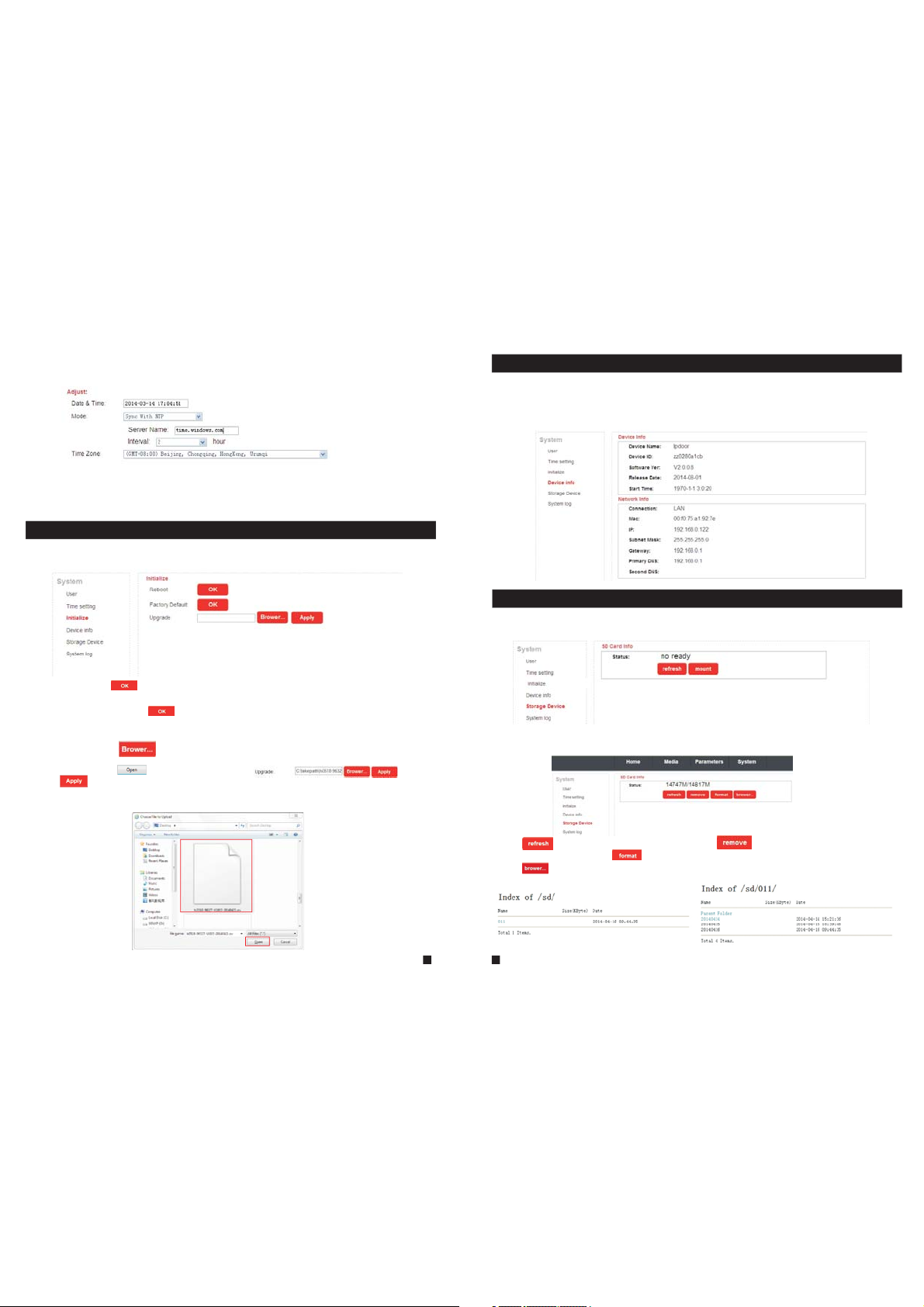
2.7.4.3 System-Initialize
Click “System—Initialize” to access initialize setting menu. This interface includes settings for
Reboot, Factory Default and Upgrade.
1) Reboot: Click “ ” , it will p op-up a m essag e windo w “the device will be rebooted. Are
you sure?”, and cl ick “OK ” to rest art the e quipm ent.
2) Factory Default: Cli ck “ ” , it wi ll po p-up a m ess age wi ndo w “Set u p dat a will b e
initialized. Are you sure?” Click “OK” to restore all the parameters to the default settings
exc ept IP ad dre ss.
3) Upgrade: Click “ ” to se lect t he fi rmwa re fi le for u pgr adin g, fo r exam ple , the
firmware file such as “hi3518-96327-V1003-20140421.ov” is on the des kto p. Fir st ch oose t he
fir mware f ile, cl ick “ ”, an d it will b e shown a s “ ”,the n
cli ck “ ” to upgrade the equipment whether or not. After the upgrading, the equipment
wil l resta rt.
Not e: Duri ng upgr ading , pleas e don’t p ower of f the i ndoo r uni t.
2.7.4.4 System-Device Info
Cli ck “Sys tem—D evice I nfo” to e nter th e “Devi ce Info rmati on” men u as foll ows. Th e inf orma tio n
included accessible through this interface includes: Device Info (Device Name, Device ID,
Sof tware Ve rsion , Relea se date a nd Star t Ti me), N etwor k Info (C onnec tion, M ac, I P, Su bnet
Mas k, Gate way, Pri mar y DNS an d Sec ond DN S).
2.7.4.5 System-Storage Device
Cli ck “Sys tem—S torag e Devic e” to ent er the in terfa ce of SD ca rd info rmati on as fol lows.
The o ption “ statu s” for th e model s witho ut SD car d will sh ow “no re ady”.
The o ption “ statu s” for th e model s with SD c ard (if t he SD car d was alr eady in serte d into th e
indoor device) will show as below.
Cli ck “ ” to ref resh th e SD card s tatus . Click “ ” t o mak e sure t o rem ove th e SD
car d wheth er or not . Click “ ” t o make su re to for mat the S D card da ta whet her o r not.
Cli ck “ ” can br owser f iles in t he SD car d.
31
32
Page 18

According to the above figure for example, click “011->20140414->r ec0 01” to e nte r into t he
rec ord lis t. Clic k one on th e list to p layba ck the re cord. C lick “P arent F older ” to back t o the
parent directory.
2.7.4.6 System-System Log
Click “System—System Log” to enter the “system log” menu as follows.
At th e top of th e “Log Se arch” p age are t he foll owing f ilter s to facilitate locating the desired file(s):
[Time] : Set the s tarti ng time a nd the en ding ti me of the l og bein g searched for.
[Ty pe]: Choose from the following options: “All”, “Alarm” and “Operation”.
Click the “ ” butto n after s ettin g the log t ime and t ype, an d the sys tem w ill di splay t he
selected log in the list. Click “ ”, “ ” , “ ”, “ ” to navigate pages, and
cli ck “ ” to delete all the log lists.
33
2.7.5 Logout
Click “Logout” to log out of the system.
2.7.6 Record(Optional)
The m odels w ithou t SD card c an't re cord.
For t he mode ls with S D card, i f the SD ca rd was al ready i nsert ed into t he indo or devi ce, whe n
some visitor press the “Call” button on the outdoor camera, the ind oor d evic e wil l star t
rec ordin g and the v ideo da ta will b e store d onto th e SD card .
The record can playback on PC.
Not e: For th e model s with SD c ard, th e SD card i nsert ed into t he indoor device must be
formatted first before using.
3. Mobile Phone Software Visit
Thi s IP vide o doo r phon e can t rans mit l ive fe ed to y our mo bil e phon e, an d supp ort P 2P for
mobile monitoring, so that you can have 'on the go' access to your surveillance system from
vir tuall y anywh ere. To vie w, you m ust in sta ll a mob ile o perating system specific program into
you r mobil e. Curr ently, t her e are a li mit ed num ber o f phon es th at are supported: Google
Android and Apple iPhone or iPad. The Android mobile program is lo cat ed on th e inc lude d CD
or do wnloa ded via “ Play St ore”, a nd an iPh one mob ile pro gram or a n iPad pr ogram i s
downloaded via “APP Store”. In “APP Store” or “Play Store”, please s earch f or
“MobileEyeDoor+”. Please see the instruction manual for your mobile to install the program.
Note:
When users access one indoor device via the software “MobileEyeDoor+” on smart-phone,
you can v iew the vid eo image of o ne outdoo r camera co nnected t o the devic e once, and
can’t v iew all ima ges of outd oor camer as connec ted to the sa me indoor unit simultaneously.
The dev ice with WI FI functi on can work i n wired net work and wi reless ne twork. Th e method to
set up WI FI functi on of the dev ice and add a n ew device v ia a smart- phone ple ase refer t o section
2.2 Soft AP Function
In wired mode or the indoor device has been connected to a wireless router, use can add the indoor
devic e via a smart -phone according to the following section.
3.1 Iphone Mobile or Ipad
The i Phone o r iPad ap plica tion, l ike all i Phone o r iPad ap plica tions , needs t o be down loade d
directly from the App Store. Open APP store, search for “MobileE yeD oor+ ”, it 's a fre e
app licat ion. Th e app lica tio n on the i Pad c ould b e sea rche d for “ iPad O nly ” or “iP hon e Only ”.
(1) “MobileEyeDoor+” installation
Acc ordin g to the fo llowi ng meth od, ope n the App st ore “ ”, to uch “ ” and s earch f or
“MobileEyeDoor+”. Install it on the mobile phone or the iPad. After installing “MobileEyeDoor+”,
it wi ll appe ar a “ Mobi leEye Door+ ” icon on t he appl icati on soft ware.
How to use “MobileEyeDoor+”
(2)
1>
Click the “MobileEyeDoor+” icon to run the program. Click “ ” t o go int o nex t inte rface,
the n click “ ” , fir st ple ase c hoos e the a ddin g typ e, the re ar e
thr ee meth ods to ad d devic e: “Sca n QR Code ”, “Man ually e nter” and “LAN Search”.
34
.
Page 19

A. Adding by “Scan QR Code”
Cli ck “ ” to the n ext i nter fac e, use rs can scan QR code attached to the machine
thr ough the mobile phone or the iPad, and the device UID will be shown.
B. Adding by “Manually enter”
Cli ck “ ” to the n ext i nter fac e, use rs ca n add a ne w dev ice by U ID ty pe or by I P
typ e.
a. By UID t ype
Afte r enter ing the “ UID Type ” Set ting s men u, the f oll owin g fie lds wi ll ne ed to be c omp lete d:
Name: Set na me for th e indoo r unit, a nd save s setti ngs for f uture u sage.
UID: The dev ice UID ( UID is at tache d to the ma chine ).
User: The user name set for entering the indoor unit system. The defaul t is “Ad min ”.
Password: The p ass word s et fo r ente rin g the in doo r unit s yst em. Th e defa ult i s “888888".
Channel Number: Set the max channels of the device will be connected.
Click “ ” to sa ve.
b. By I P type
Cli ck “IPTy pe” to en ter the S ettin gs menu , the fol lowin g field s will ne ed to be co mplet ed:
Name: Set n ame for t he indo or unit , and sav es sett ings fo r futur e usage.
Address: The p ubl ic IP ad dres s or dy nami c dom ain na me of t he ind oor u nit.
Port: The m obi le por t of th e indo or un it for r emo te acc ess v iewi ng vi a mobi le ph one or i Pad ,
the default is “20510”.
User: The u ser n ame se t for e nter ing t he ind oor u nit sy ste m. (Ad min by default)
Password: The p ass word s et fo r ente rin g the in doo r unit s yst em. (8 888 88 by de fau lt)
Channel Number: Selec t the max c hanne ls of the d evice w ill be co nnect ed.
Cli ck “ ” to sav e.
C. Adding by “LAN Search”
On LA N, turn o n the WIF I of the Wi reles s Route r and the m obile phone(or the ipad). Click
“LAN Search” and online devices will appear on the “Please choose the device” list, click
one to add the device, the following fields will need to be completed:
Name: Set n ame for t he indo or unit , and sav es sett ings fo r futur e usage.
User: The u ser n ame se t for e nter ing t he ind oor u nit sy ste m. (Ad min b y defa ult )
Password: The password set for entering the indoor unit system. (888888 by de faul t)
Channel Number: Se t the ma x cha nnel s of th e devi ce wi ll be co nne cted .
Cli ck “ ” to sav e.
35
36
Page 20

2> After adding the device successfully, the device will appear on the main screen. Click the
dev ice, an d all the c hanne ls of the d evice w ill be sh own on th e scree n. Clic k any cha nnel an d
it will connect immediately. The background of the channel will be hi ghlig hted af ter con necti ng
successfully(shown as follows).
ipdoor 2014-07-29 10:21:30
3> The fu nctions o f the other i cons on the l ive view:
Unlock.
Snapshot .
of the channel has a norm al recording video symbol “[REC]”. And click it again to stop manual
record.
Click i t to turn the s ound on or di sable.
Click i t to start to t alk, and th e backgro und of the bu tton will b e highlig hted. Cli ck it again t o
stop talking.
Click i t to displa y or hide the b uttons “ ”.
Click i t to enter th e device li st interf ace.
Click i t to enter th e snapsho t file and re cord file .
Click i t to enter th e local set ting inte rface.
Click i t to enter us er guide in terface .
4> On the l ive view, use rs can touc h a channel o n the scree n and drag it t o the other c hannel
position directly.
5> On the i nterfac e of “Devic e”, user ca n edit the pa rameter s of one devi ce, click “ ” t o the next
inter face as bel ow. Click “ ” to en ter edit mo de to adjus t the param eters. Cl ick “ ” to save .
And cli ck “ ” to remov e the infor mation of t he current device.
: to capt ure a frame o f the video s tream as a st ill photo
Recor d: Click it t o start man ual recor d video on th e current c hannel, and the right top corner
unit and the mobile phone are both connected to internet.
Note:
1) First please make sure alert about the program “MobileEyeDoor+” on iPhon e or iPad could be s hown in
Notif ication Ce nter, user can e nter into th e menu “Sett ings->No tificati on Center- >Include ” to set up “Bad ge
APP Icon, So unds, Shown in N otificatio n Center” to be “O N”.
2) When t he option “v ideo push” o n the mobile s oftware in terface is s et to “On”, so meone pres s the call but ton
on any ou tdoor came ra, the noti fication m essage wil l be pushed on to the maste r’s phone or i Pad (Shown as
below f igure). And us ers can clic k the alarm li st to access t o the video li ve view of the c hannel dir ectly or
acces s to the video l ive view to un lock for the o utdoor cam era .
3) The ala rm push functi on can be effecti ve, and the devi ce must be added b y UID type.
[WIFI S etting] : To access the interface about the parameters of one device, there is an option
“WIFI S etting” f or the indo or device w ith WIFI fu nction. C lick “WIFI setting”, and available wireless
devic es will be sh own on the li st. Choos e one and cli ck it, if the wireless password of the wireless
router is enabled, it will pop-up a window to en ter the pas sword of th e wireles s router, inp ut the
correct password and setting ok, the indoor device will reboot auto matical ly, it will be con nected to
the wireless router after starting when hearing a bee p again.
Note: If users want to connect the device via wireless network, whe n the device r estarts au tomatica lly
after completing set of the parameters about WIFI, please unplug the Ethernet cable connected to the
devic e, otherwi se the devic e will run via w ired netwo rk.
6>
Click “ ” t o enter the s napshot a nd record f ile inter face. Cli ck “Photo s” or “Reco rds” to swi tch
displ ay interf ace. Click “ ” t o enter edi t
mode, u sers can re move the fi le list tha t they want t o.
Click one on the list to see the picture or the record.
[Video Push]: To access the interface about the parameters of one device, there is an op tion
“vide o push” for a larm push f unction . When sele ct “On”, it i ndicates that the alarm push function of
the cur rent devi ce is enabl ed. To enable ala rm push fun ction, users need to make sure the indoor
37
38
Page 21

7> Clic k “ ”to enter th e “System S ettings ” interfa ce as follo ws.
[Video Views]: Se lec t “1" an d onl y one ch ann el vie w wil l be sho wn
on li ve view. S elect “ 4" and qu ad chan nels vi ew will b e shown o n
liv e view.
[Live Preference]: Options include “Real-time” and “Quality”. If
cho ose “Re al-ti me”, th e video e ncode r of the ch annel f or remo te
If choose “Quality”, the video encoder of the channel for remote ac ces s view ing v ia mob ile
phone will consider to the image quality first.
[View Preference]: To set up the image display size when view the channel video. O ptio ns
include “”original” and “tile”.
acc ess vie wing vi a mobil e phone w ill con sider t o the fra me firs t;
3.2 Android Mobile
1) Please go to the android software market “Play Store” to search for “MobileEyeDoor+” and
insta ll it. Or fro m the insta llation C D, copy the s etup soft ware “MobileEyeDoor+.apk” to user's
Android phone or to SD card.
Open your “File Manager” in android phone, and find out the file “Mobil eEyeDoo r+” in your
android phone memory or SD card. Click it to install the software. When t he applic ation has
finished installing, the icon “MobileEyeDoor+ ” will dis play on the s creen of th e phone (sh own
as below).
2) Clic k the “Mobi leEyeDo or+” icon t o run the pro gram, cli ck “ ” to the nex t interfa ce, first p lease
choose the adding mode “Add a wired de vice & inst alled wir eless device”, and on the interface
“Select Add way” to select adding type, there are three methods to add devi ce: “Two-di mension al
code scanning”, “Manually enter” and “LAN Search”.
A. Adding by “Two-dimensional Code Scanning”
Cli ck “ ” to the n ext i nter fac e, use rs ca n scan t wo- dime nsi onal c ode a ttac hed
to the machine through the mobile phone, and the device UID will be sho wn.
B. Adding by “Manually enter”
Cli ck “ ” to the n ext i nter fac e, use rs ca n add a ne w device by UID type or by IP type.
a. By I P type
Aft er ente ring th e “IP” Se tting s menu, t he foll owing f ields w ill nee d to be com plete d:
Name: Set n ame for t he indo or unit , and sav es sett ings fo r futur e usage.
Address: The public IP address or dynamic domain name of the indoor unit.
Port: The m obi le por t of th e indo or un it for r emote access viewing via mobile phone, the
def ault is “ 20510 ”.
User: The user name set for entering the indoor unit system. (Admin by d efa ult)
Password: The password set for entering the indoor unit system. (888888 by de faul t)
Channel Number: Selec t the max c hanne ls of the d evice w ill be co nnect ed.
Cli ck “ ” to sav e.
b. By U ID type
Cli ck “UID ” to ente r the Set tings m enu, th e follo wing fi elds wi ll need t o be comp leted :
39
40
Page 22

Name: Set na me for th e indoo r unit, a nd save s setti ngs for f uture u sage.
UID: The dev ice UID ( UID is at tache d to the ma chine ).
User: The us er na me set f or en teri ng th e indo or un it sys tem . The de fault is “Admin”.
Password: The p ass word s et fo r ente rin g the in doo r unit s yst em. Th e defa ult i s “888 888 ".
Channel Number: Se t the ma x cha nnel s of th e devi ce wi ll be co nne cted .
Click “ ” to sa ve.
C. Adding by “LAN Search”
On LAN, turn on the WIFI of the Wireless Router and the mobile phone. Cli ck “LAN Sea rch”
and online devices will appear on the “Search number of device” lis t, cli ck one to a dd the
device, the following fields will need to be completed:
Name: Set na me for th e indoo r unit, a nd save s setti ngs for f uture u sage.
User: The us er na me set f or en teri ng th e indo or un it sys tem . The de faul t is “A dmin ”.
Password: The p ass word s et fo r ente rin g the in doo r unit s yst em. Th e defa ult i s “888 888 ".
Channel Number: Se t the ma x cha nnel s of th e devi ce wi ll be co nne cted .
Click “ ” to sa ve.
3) After adding the device successfully, the device will appear on the main screen. Click the
dev ice, an d all the c hanne ls of the d evice w ill be sh own on th e scree n. Clic k any cha nnel an d
it will connect immediately. The background of the channel will be hi ghlig hted af ter con necti ng
successfully(shown as follows).
ipdoor 2014-07-21 10:21:03
4) The fu nctions o f the other i cons on the l ive view:
Unloc k.
Snaps hot .
of the ch annel has a n ormal recording video symbol “[REC]”. And click it again to stop manual
record.
Click i t to turn the s ound on or di sable.
Click i t to start to t alk, and th e backgro und of the bu tton will b e highlig hted. Cli ck it again t o
stop talking.
Click i t to display or hide the buttons “ ”.
Click i t to enter th e device li st interf ace.
Click i t to enter th e snapsho t file and re cord file .
Click i t to enter th e local set ting inte rface.
Click i t to enter us er guide in terface .
5) On the l ive view, use rs can touc h a channel o n the scree n and drag it to the other channel
position directly.
6) On the interface of “Devices”, user can edit the parameters of one dev ice, clic k “ ” to the next
inter face as bel ow. Click “ ” to en ter edit mo de to adjust the parameters. Click “ ” to save.
And cli ck “ ” to remov e the infor mation of the current device.
[Alarm Setting]: To access the interface ab out the par ameters o f one devic e, there is an option
“Alar m Setting ” for alarm p ush funct ion. When s elect “On ”, it indic ates that t he alarm pu sh functi on
of the cu rrent dev ice is enab led. To enable al arm push fu nction, u sers need t o make sure t he
indoor unit and the mobile phone are both connected to internet.
Note: 1 )When the o ption “Al arm Setti ng” on the mo bile soft ware interface is
set to “O n”, someo ne press th e call butt on on any out door came ra, the
notif ication m essage wi ll be pushe d onto the ph one(sho wn as the right
figure). And users can click the alarm list to access to the video l ive view
of the ch annel dir ectly or ac cess to the v ideo live v iew to unlo ck for the
outdoor camera.
2) The al arm push fu nction ca n be effect ive, and th e device mu st be
added b y UID type.
[WIFI Setting]: To access the interface about the parameters of one device,
there i s an option “ WIFI Sett ing” for th e indoor de vice. Cli ck “WIFI setting”,
and ava ilable wi reless de vices wil l be shown on t he list. Ch oose one an d
click i t, if the wir eless pas sword of th e wireles s router is e nabled, i t pop-up a
windo w to enter th e passwor d of the wire less rout er, input the correct
passw ord and set ting ok, th e indoor de vice will r eboot aut omatica lly, it will be c onnecte d to the
41
42
: to capt ure a frame o f the video s tream as a st ill photo
Recor d: Click it t o start man ual recor d video on th e current c hannel, and the right top corner
Page 23

wireless router after starting when hearing a beep again.
Note: I f users wan t to connec t the devic e via wirel ess netwo rk, when th e device re starts
autom aticall y after com pleting s et of the par ameters a bout WIFI , please unplug the Ethernet
cable c onnecte d to the devi ce, other wise the de vice will r un via wire d network .
7) Clic k “ ” to enter th e snapsho t and recor d file inte rface. Cl ick “snap shot” or “r ecord” to s witch
displ ay interf ace. Click “ ” t o enter edit
mode, u sers can re move the fi le list tha t they want t o.
Click o ne on the lis t to see the pi cture or th e record.
Appendix 1. Accessing the indoor unit via Mozilla Firefox
1.Firs t, instal l Firefox o n Windows (This doc ument wil l use Firef ox 28.0 as an e xample) .
2. After in stallin g Firefox , please se arch for th e “IE Tab” add-on f or Firefo x, which ca n be
downloaded from Firefox browser.
3. Open Firefox, click “Tools-->Add-ons” to enter into the interface of “ Get Add-ons ”, and sear ch
for “IE Tab”, a ll the IE tab s will be sho wn on the lis t for “Available Add-ons”. Choose one and install
it, thi s documen t will use IE Tab 2(F F 3.6+)5. 12.12.1 f or example.
4. After in stallin g the IE Tab, user ne ed restar t Firefox b rowser.
5. Open F irefox an d enter the i ndoor uni t IP addres s in the addr ess field . Right-c lick at bla nk,
selec t “View Pag e in IE tab”. Th e indoor un it can now be c onnected successfully.
Appendix 2. Accessing the indoor unit via Google Chrome
1.First, installing Google Chrome Browser on Windows(this manual will use C hrome ver sion
34.0. 1847.116 m as a n example ).
2. After in stallin g Google Ch rome, sea rch for the “ IE Tab ” add-on fo r Chrome, w hich can be
downloaded from the Chrome Web Store.
3. Opening Chrome, click “ Cust omize and c ontrol Go ogle Chrome->Tools->Extensions->
brows er the gall ery” to ent er the “Chr ome Web Sto re” inter face to sea rch for “IE Tab”, an d results
for IE ta b in Extens ions will a ppear on th e right sid e. Choose o ne to insta ll it and it’ s free for
installation(Shown as below).
8) Click “ ”t o enter the “ System Se ttings” i nterfac e as follow s.
[Video Views]: Op tio ns inc lud e “1" an d “4" . Sele ct “1 " and on ly on e
cha nnel vi ew will b e shown o n live vi ew. Sele ct “4" an d quad ch annels
vie w will be s hown on l ive vie w.
[Vi deo S tyle ]: Op tion s inc lude “ Ori gina l” an d “Cov ere d”.
43
44
Page 24

4. During installation, the following figure will appear, click “Ad d” to confi rm to insta ll “IE Tab”
add-on.
5. After co mplete in stallat ion, the ic on “ ” will app ear on the ri ght top of th e browser i nterfac e
(Show n on the red fr ame as belo w), and it me ans that IE Tab has b een added t o Chrome br owser.
6. Clic k the icon “ ” on t he right of t he addres s field to di splay the C hrome web p age in an
IE-based page, and fill in the IP address of the indoor unit on the IE-based address bar, then click
the ico n “ ” to access t he remote d evice, fi ll in the cor rect user n ame and pas sword to lo g in.
Default user name and password are “Admin” and “888888".(shown on the red frames as below)
Appendix 3 How to ensure reliable remote viewing of the
indoor unit through IE browser on Win 7/Win 8 64bit OS
1. Run 32bit IE on Windows OS (64bit)
Note: On a 64- bit ver sion of a W indows operating system, there are two versions of the
Internet Explorer files:
45
* The 64-bit version is “C:\Program Files\ Internet Explorer \iexplore.exe”.
* The 3 2-b it ver sio n is “C: \Pr ogra m Fil es(x 86) \ I nter net E xplorer \iexplore.exe”.
* Ple ase run t he “C:\ Progr am File s(x86 ) \Internet Explorer \iexplore.exe”.
2. Run Internet Explorer as the Administrator
1) Open folder path “C:\Program Files(x86) \Internet Explorer”.
2) Right click the Internet Explorer icon and choose "Run as Administrator".
3) Click "Continue" in the User Account Control window to grant administrator access to
Internet Explorer.
3. Download ActiveX control after type in IP address & Po rt
1) Op en an Int ernet E xplor er brow ser win dow to ma ke chan ges to your current ActiveX controls.
Cli ck the “Too ls” lin k locat ed at the t op of the m enu bar. A dro p down wi ndow wi ll appe ar with
sev eral mo re opti ons to ch oose fr om. Eac h optio n will le t you cha nge som e of the de fault
settings already programmed into Internet Explorer.
2) Click the “Internet Options” link located at the end of the list. Wh en the p op-up wind ow
appears, select the “Security” tab to access the ActiveX controls. There are several zones with
mul tiple s ecuri ty sett ings. E ach zon e has pre set set tings b uilt in to it. You ca n chang e the
settings to fit your current needs. If for some reason you're not sat isf ied wi th these ch ang es,
click the “Reset All Zones to Default Level” to change them back. To al low Ac tive X con trol s to
run, click the “Internet” zone. The icon that identifies this zon e look s lik e Eart h.
46
Page 25

3) Change the security level for the “Internet” zone from the defau lt “M ediu m-h igh” z one t o
“Medium". Slide the bar up and down between the different securit y zone s. The “ Med ium”
Int ernet z one wil l allow a l ower security environment for your web browsing. To go even
further with enabling the ActiveX controls, click the “Custom Level” button. Under the
“Settings” menu, look for the “ActiveX Controls and Plug-ins” opti ons. N orm ally, t hese
settings are disabled to prevent a secu rit y risk t o you r comp ute r system.
4) Allow the ActiveX controls to automatically run by changing the se tti ngs fr om “D isab le” t o
“Enable”. This can be done by clicking the “Enable” button next to “Allow Previously Unused
Act iveX Co ntrol s to Run wi thout P rompt ”. After m aking t hese ch anges to your Internet
Explorer browser, you won 't be con stant ly prom pted to e nable t he ActiveX controls. They'll
aut omati cally b e allow ed with out pro mptin g you to ma nuall y do so. Th e cha nges m ade i n
the se sett ings wi ll not ta ke full e ffect u nti l you cl ose a nd res tar t the In ter net Ex plo rer br ows er
window.
4. Fix site display problems with Compatibility View
Som etime s a websi te you' re visi ting do esn't l ook lik e you expect it to. Images might not show
up, menus might be out of place, and text boxes could be jumbled together. This can be caused
by a co mpatibility problem between Internet Explorer and the site you're on . When a s ite i s
inc ompat ible wi th Inte rnet Ex plore r, you'll see the Compatibility View button in the Address bar.
You ca n only t urn o n Comp ati bili ty Vie w in Inte rnet Ex plore r for the d eskto p.
A. To turn on Compatibility View
1) Se e if the Co mpati bilit y View bu tto n appe ars i n the Add res s bar. (I f you d on't s ee th e
but ton, th ere's n o need to t urn on Co mpati bilit y View.)
2) Tap or c lic k the Co mpa tibi lit y View b utto n to di spla y the s ite in C omp atib ili ty Vie w.
Once you turn on Compatibility View, Internet Explorer will auto mati cal ly sho w tha t site i n
Compatibility View each time you visit. You can turn it off by ta ppi ng or cl ick ing th e but ton
again. Or, you can c lear th e entir e list of s ites us ing Com patib ility V iew b y dele tin g your
browsing history.
B. To cl ear t he lis t of Co mpat ibi lity V iew si tes
Not all website display problems are caused by browser incompatibility. Interrupted Internet
connections, heavy traffic, or problems with the website can also aff ect ho w a page is d ispla yed.
If yo u're ha ving ot her pro blems o n a site, s uch as pl aying v ideos , read Vi deo w on't p lay i n
Internet Explorer.
The Compatibility List is frequently updated, and Internet Explorer automatically downloads
these update. This list includes sites that might've been designed fo r old er or ot her b rows ers ,
sit es that u se Adobe F lash Pl ayer, an d other s ettin gs that h elp giv e you a bet ter bro wsing
experience. If you don't want these updates, you can turn off Compa tibi lit y List U pda tes at
any time.
C. To turn off Compatibility List Updates
1) Op en Inte rnet Ex plore r in the de sktop .
2) Pr ess the Al t key to di splay t he Menu b ar (or pr ess and h old the Address bar and then select
Menu bar).
3)Tap or click Tools, and then tap or click Compatibility View settings.
4) Clear the Download updated compatibility lists from Microsoft c heck b ox, a nd the n tap o r
click Close.
D. To change Compatibility View settings
1) Open Internet Explorer in the desktop.
2) Pr ess the Al t key to di splay t he Menu b ar (or pr ess and h old the Address bar and then select
Menu bar).
3) Tap or click Tools, and then tap or click Compatibility View settings.
47
* If ther e is any doubt o r disputab le regardi ng informa tion in this m anual, you c an call our co mpany for
clari fication .
* There ma ybe some differ ences betwee n the descrip tions prov ided here an d the actual d evices, as o ur
produ cts are cons tantly dev eloping an d upgradin g. We apologi ze if this manua l does not conta in all of the
lates t updates. Thanks.
48
Statement
Page 26

FCC Notice
This device complies with Part 15 of the FCC Rules. Operation is
subject to the following two conditions:
(1) This device may not cause harmful interference, and (2) this device must accept any
interference received, including interference that may cause undesired operation.
NOTE 1: This equipment has been tested and found to comply with the limits for a Class B digital
device, pursuant to part 15 of the FCC Rules. These limits are designed to provide reasonable
protection against harmful interference in a residential installation. This equipment generates, uses
and can radiate radio frequency energy and, if not installed and used in accordance with the
instructions, may cause harmful interference to radio communications. However, there is no
guarantee that interference will not occur in a particular installation. If this equipment does cause
harmful interference to radio or television reception, which can be determined by turning the
equipment off and on, the user is encouraged to try to correct the interference by one or more of
the following measures:
- Reorient or relocate the receiving antenna.
- Increase the separation between the equipment and receive r .
-Connect the equipment into an outlet on a circuit different from that to which the receiver is
connected.
-Consult the dealer or an experienced radio/TV technician for help.
NOTE 2: Any changes or modifications to this unit not expressly approved by the party
responsible for compliance could void the user's authority to operate the equipment.
 Loading...