

Page 1
4-wire villa high definition video
intercom system
Page 2

LIMITATIO N OF L IA BI LI TY
This users' manual is supplied 'as is', with no warranties, be it expressed or implied, including,
※
but not l imited t o, the imp lied war rantie s of merch antabi lity, suit abilit y for any ex act purp ose, or
non-infringement of any third party's rights.
This publication may include technical inaccuracies or typos. The manufacturer holds the right
※
to introduce any changes to the information contained herein, for any pur pose, in cludin g but not
limit ed to, imp roveme nts of the p ublica tions an d/or rel ated to th e produc t, at any ti me, with out
prior notice.
DISCLAIMER OF WARRANTY
The supplier shall not be liable to any party or any person, except for rep laceme nt or reas onable
maintenance of this product, for the cases, included but not limited to the following:
※
Any dam age or los s, inclu ding but n ot limit ed to: dir ect/in direct, consequential, special, exemplary,
arisi ng out of or r elated t o the prod uct;
※
Inappropriate use or negligence of the user in operation of the produ ct, resu lting in p ersona l injury
or any damage;
Unauthorized disassembly, repair or modification of the product by the use r;
※
※
Any problems or consequential inconvenience, loss or damage, caused by connecting this product
to devices of the third parties;
Any claim or action for damages, brought by any photogenic subject, be it a per son or org anizat ion,
※
due to violation of privacy whereby the pictures taken by the device and/or saved data become
public or are used for the purposes other than intended.
SAFETY INSTRUCTIONS
※
Read th ese inst ructio ns and kee p them in a sa fe place f or futur e refere nce.
※
Please refer all work related to the installation of this product to qualif ied serv ice pers onnel or
system technician.
※
Do not operate the appliance beyond its specified temperature, humidity or power source ratings.
Securely install the devices on vertical surfaces (solid walls/doors) not p rone to vi bratio n or impac t.
※
Insta ll the dev ices awa y from hea t source s such as ra diator s, heat re gister s and stov es.
※
Installation of the terminal near consumer electronics devices, e.g. ster eo recei ver/am plifie rs and
televisions, is permitted as long as the air surrounding the terminal doe s not exce ed the abo ve
mentioned temperature range.
Handle the appliance with care. Do not strike or shake, as this may damag e the devi ce.
※
※
The doorbell/camera units should be fitted with an approved weather shi eld if the c hosen po sition
is in dir ect sunl ight, or i n contac t with rai n, snow or i rrigat ion spri nkler sy stems.
Do not us e strong o r abrasi ve deter gents wh en clean ing the ap pliance body. When the dirt is
※
hard to r emove, u se a mild de tergen t and wipe g ently.
※
Do not ov erload o utlets a nd exten sion cor ds as this m ay resul t in a risk of f ire or ele ctric sh ock.
Distributing, copying, disassembling, reverse compiling, reverse engineering, and also exporting
in viol ation of e xport la ws of the so ftware p rovide d with thi s product, is expressly prohibited.
CARING FOR THE ENVIRONMENT BY RECYCLING
When yo u see this s ymbol on a p roduct , do not dispose of the product with
residential or commercial waste.
Recycling your electrical equipment
Please do not dispose of this product with your residential or commercial waste. Some countries or
regions, such as the European Union, have set up systems to collect and recycle electrical and electronic
waste items. Contact your local authorities for information about practices established for your region.
COPYRIGHT STATEMENT
All rights reserved. No part of this publication may be reproduced in any for m or by any me ans,
transcribed, translated into any language or computer language, transfo rmed in an y other wa y,
store d in a retrieval system, or transmitted in any form or by any means, electronic, mechanical,
recor ding, ph otocop ying or ot herwis e, witho ut the pri or writt en permission of the owner.
1 2
Page 3

Table of Contents
Table of Contents
LIMITATION OF LIABILITY..............................................................................1
DISCLAIMER OF WARRANTY.........................................................................1
SAFETY INSTRUCTIONS...............................................................................1
CARING FOR THE ENVIRONMENT BY RECYCLING........................................2
COPYRIGHT STATEMENT..............................................................................2
Table of Contents ...........................................................................................3
1. Description Of The Indoor Unit.....................................................................5
1.1 Description On The Indoor Monitoring.....................................................5
1.2 Description On LED Indicator.................................................................6
1.3 Description On Symbol..........................................................................6
1.4 Specifications of the Indoor Unit.............................................................7
1.5 Fitting for the Indoor Unit ......................................................................7
1.6 Wiring Diagram ....................................................................................8
1.7 Note On Wiring Connection...................................................................9
1.8 Installation Process of Indoor Units .....................................................10
1.9 Operation Introduction .......................................................................11
2. System Settings For Indoor Units................................................................14
2.1 Mouse Control.....................................................................................14
2.2 Tool Bar ..............................................................................................14
2.3 Tool Bar Menu Options .........................................................................14
2.3.1 S etu p ..... ... .................................................................................14
2.3.2 M anual Recording .......................................................................15
2.3.3 Video Playback ...........................................................................15
2.3.4 Ring Setting ................................................................................16
2.4 Menu Options .....................................................................................16
2.4.1 S yst em .... ... ................................................................................16
2.4.1 .1 System-Basic ...................................................................17
2.4.1 .2 System-Time ....................................................................17
2.4.2 N etwork ......................................................................................18
2.4.2 .1 Ne twork-Basic ..................................................................18
2.4.2 .2 Ne twork-Port ....................................................................18
2.4.2 .3 Ne twork-Advanced ............................................................19
2.4.3 R eco rd Sche dul ing ... ... ..... ... ..... ... ..... ... ..... ....................................21
2.4.4 Al arm . ..... ... ..... ... .........................................................................22
2.4.5 M aintenance ........................ .......................................................22
2.4.5.1 SD ...................................................................................23
2.4.5.2 Upgrade .......................................................................... 23
2.4.6 User ........................................................................................... 24
2.4.7 Default ........................................................................................24
2.4.8 Information ................................................................................. 24
3 4
2.4.9 Save/Exit...................................................................................25
3. Web Browser Operation............................................................................25
3.1 Feature.............................................................................................25
3.2 Network Security Setting....................................................................25
3.3 Connection Settings ..........................................................................26
3.4 Con tro l Downl oad a nd Inst all ation . .....................................................27
3.5 Ope rat ion Int erf ace ...........................................................................28
3.5.1 L ive . ..... ... ..................................................................................28
3.5.2 C ont rols .. ... ..... ...........................................................................29
3.5.3 O the r Operations ........................................................................29
3.5.4 P lay back .. ... ...............................................................................29
3.5.5 Toolba r Gui de .... ... ..... . ...............................................................31
3.5.6 R emo te Sett ing s ..... ... .................................................................31
3.5.7 L oca l Settings .............................................................................34
3.5.8 L ogout .......................................................................................35
4. Mobile Phone Software Visit ......................................................................35
4.1 Iph one M obile o r Ipa d ..... ... ..... ... ..... ....................................................35
4.2 Andr oid M obile . ... ...............................................................................38
Appendix 1. Accessing the indoor unit via Mozilla Firefox .............................42
Appen dix 2 . Access ing t he indo or un it v ia Go ogl e Ch rom e ... .. .......................43
Appendix 3. Remote Control(Optional)................................................................44
Page 4
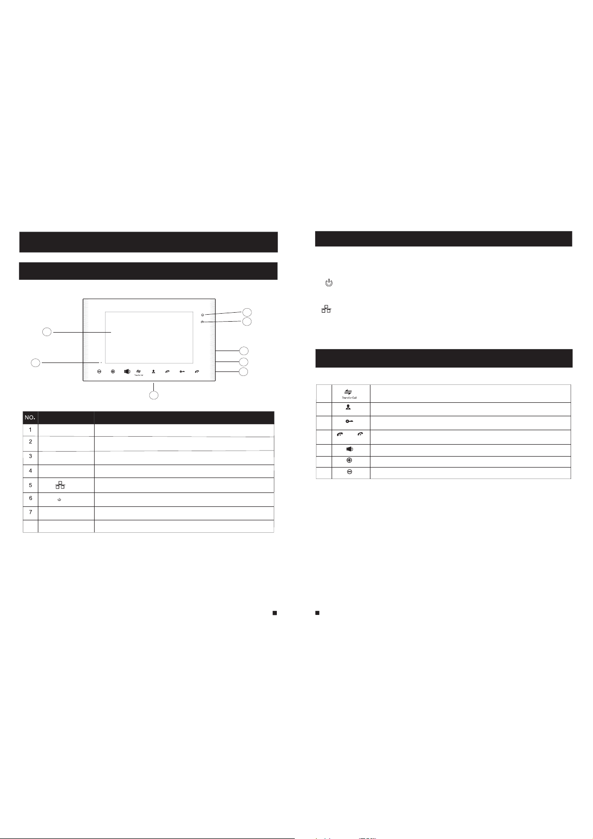
1. Description Of The Indoor Unit
1.1 Description On The Indoor Monitoring
1
1.2 Description On LED Indicator
In the pa nel you ca n find out t hree LED indicators , w ith the de tailed d escriptions,
pleas e see the be low:
LED 1
The pow er indic ator of th e indoor u nit
6
5
LED 2
Network link LED, LED lights indicate that the device connected to the Ethe rnet.
2
TFT display
Microphone
Operation buttons
Speaker
USB Port
8
SD Port
Name
Volume
Up/+
Down/-
Monitoring
Hang up
Unlock
Talk
3
Descriptions
View visitor’s image displayed on the TFT screen
Transm it the voi ce to outd oor came ra
Human body sensor touch buttons
Sound f rom outd oor came ra
Network LED
Power LED
To connect the USB mouse to the device
SD card i nterfa ce, supp ort up to 32 G SD card fo r record ing.
4
7
1.3 Description On Symbol
8
1
2
Monitoring
3
Unlock
4
Talk
5
Volume
6
7
Down/-
5
6
Call transfer to other indoor monitor/ Watch the outside image from th e
external camera under the standby model
Obser ve the ima ge of came ra view at e ntranc e in real ti me
Relea se the doo r lock
Hang up
Activ ate conv ersati on mode by p ressin g this but ton
Adjust volume
Increase volume
Up/+
Decrease volume
Page 5
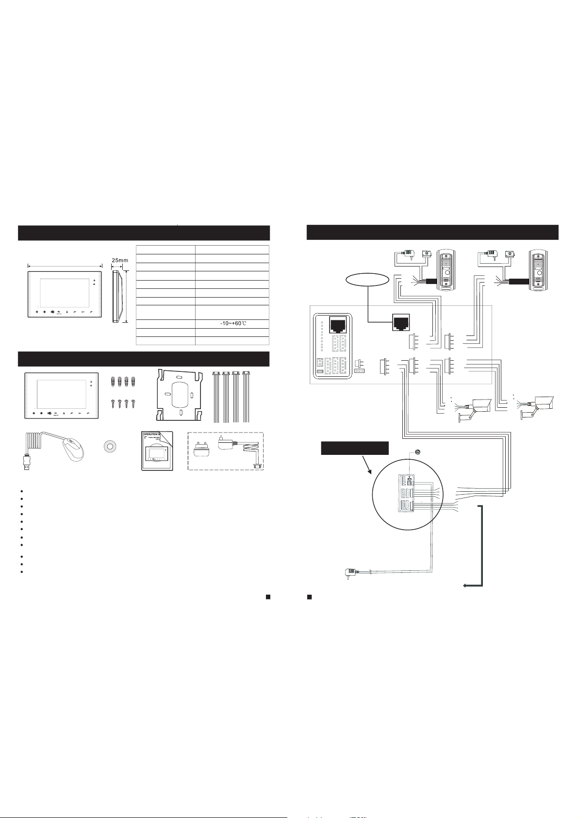
1.4 Specifications of the Indoor Unit
Display
304mm
Resolution
Video system
Intercom mode
Conversation duration
Standby status
working status
Volume
Monitoring
Up/+
Down/-
Hang up
Unlock
Talk
197mm
Power supply
Operation temp.
Installation
Dimensions
1.5 Fitting for the Indoor Unit
Volume
Up/+
Down/-
Hang up
Monitoring
Unlock
Talk
10.1 inch TFT LCD(16:9)
1024(H)X3(RGB)X600(V)
PAL/NTSC compatible
Semi-
Duplex communication
120 seconds
1A max.
1.5A max.
DC 2V/2A
1
Built-in switching power supply
(apply to AC100V-240V)
Surface mount
304*197*25mm
1.6 Wiring Diagram
internet
DOOR2
DOOR1
GND
Power
ISP
CAM2
OUT
DC12V
CAM1
SCL
SDA
GND
AC/DC p ower
DC12V
AUDIO
GND
VIDEO
AUDIO
GND
DATA
VIDEO
OUT
DOOR2
CAM2
NET
DC12V
AUDIO
GND
VIDEO
DC12V
AUDIO
GND
VIDEO
lock
DOOR2
DC12V
AUDIO
GND
VIDEO
DOOR1
DC12V
AUDIO
GND
VIDEO
CAM1
DC12V
D
N
G
GND
Video
AC/DC power
DC12V
AUDIO
GND
VIDEO
CAM2
lock
D
GND
GND
V
DOOR1
12V
C
ideo
CAM1
Monitoring
Hang up
Up/+
Unlock
Talk
Down/-
Volume
Optional
Indoor Unit ------------------------------------------------------------ ------ ------ ------ ------ -- 1 pcs
Plastic Anchors ------------------------------------------------------------------------------- 4 pcs
Screws ------------------------------------------------------------------------------------------ 4 pcs
Bracket ------------------------------------------------------------------------------------------ 1 pcs
4 Pin Line --------------------------------------------------------------------------------------- 4 pcs
TF Card for SD Card Sets ------------------------------------------------------------------- 1 pcs
This Quick Guide------------------------------------------------------------------------------ 1 pcs
External Switching Power Adapter(optional)----------------------------- ------ ------ ---- 1 pcs
USB Mouse(optional)--------------------------------------------------- ------ ------ ------ ----- 1 pc s
Remote Control(optional)--------------------------------------------------------------------- 1 pcs
Installation CD(with full manual and android mobile phone software)---- ------ ----- 1 pc s
Extention Monitor
IN
OUT
pin
short
2P
Pulled
AUDIO
GND
DATA
VIDEO
AUDIO
GND
DATA
VIDEO
External switching power supply(DC 12V)
To next extention unit
7
5
8
Page 6
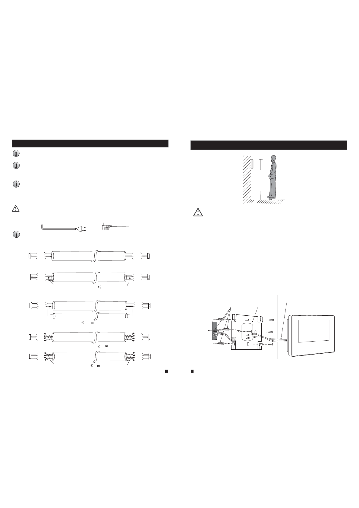
1.7 Note On Wiring Connection
The electric lock source camera is not include in the package, you can purchase
an electric lock which is suitable for you need
In the standard delivery the system supports locks with Normally Open (N.O.) door unlocking
method. It means that in the normal state the dry contact is opened so the lock is kept under
constant closed state. If the unlocking push-button is pressed and the dry contact is changed
to closed, then the lock is released.
Please note that the 2P Short Pin is designed for programming the indoor monitor ,
the indoor monitor will be programmed to main monitor if you plug the 2P Short Pin in;
however the indoor monitor will be programmed to extension monitor if the 2P Short
Pin is pulled out. Setup ok, after power machine automatically detects, if it is in state
machine work Set, need makes the machine to detect electric
Indoor machine power with a built-in power and the external power optional.
Please refer to actual control using
Source,
pull out the AC power plug before installation of device(shown as Below).
Applicable to wide voltage range (AC100V-240V)
Use and selection of wire, please refer to the following.(The actual effect and the quality of wire
rod has the very big relations)
1. 4C ordinary unshielded and shielded wire connection mode:
Distance
≤28m(4*0.2mm );
DC12V
AUDIO
GND
VIDEO
Unshielded wire
DC12V
AUDIO
GND
VIDEO
Shield
.If the indoor machine with a built-in
2
Distance
≤50m(4*0.3mm
50m)
≤
(
Shielded wire
(
80m)
2
)
Shield
2.3C ordinary unshielded +video wire(75-3)connection mode:
DC12V
AUDIO
GND
VIDEO
.
Please first
;
Distance
Power
≤80m(4*0.5mm ).
DC12V
AUDIO
GND
VIDEO
DC12V
AUDIO
GND
VIDEO
DC12V
AUDIO
GND
VIDEO
1.8 Installation Process of Indoor Units
150-160cm
NOTE:
* Avoid ins tallat ion of the d evice ne ar stron g radiat ion e.g. T V set, vid eo recor der and PC
etc.
* Maint enance s hould be c omplie d with a qua lified t echnician.
* Avoid har d shake , be ating an d collision ,otherwise the internal exact components
2
maybe b e damage d .
* Selec t the most s uitabl e positi on where t he monit or is loca ted at use r's eye le vel.
* Switch off power supply before installing.
* Keep mo re than 30 cm away fr om AC power s upply to avoid external interference.
* Keep it a way from t he water a nd magne tic fiel d.
To install the indoor unit , please follow these steps as below :
Connection
Plastic anchors
Bracket
cable
(
)
))()
3.CAT5 or CAT6 network cable connection mode:(Not recommended)
DC12V
AUDIO
GND
VIDEO
Unshielded network cable
DC12V
AUDIO
GND
VIDEO
Shield
Shielded network cable
100
DC12V
AUDIO
GND
VIDEO
)
20
(
(
40
Shield
)
)
DC12V
AUDIO
GND
VIDEO
9
10
Page 7

1.9 Operation Introduction
VISITOR CALL
◆
Please be aware of Connection of 2 outdoo r camera s is requi red.
Standby mode
The Vis itor pre ss
the call button on
outdoor camera 1
A 10s of continuous
Ding Do ng tone is h eard
inside and outside
The visitor’s image
automatically displayed on
the screen
Press the talking
button
Talk
Stop ringing
Start conversation
with outdoor camera
The conversation
duration is 120s
at a ti me
Press the unlock
button on indoor
monitor
Both th e visito r s voice an d image wi ll be not sw itched o ff withi n 20s of tim e span whe n the
unlock button i s presse d, this in dividu alized f unctio n allow yo u to make su re whet her the
visit or alrea dy come in .
release the
door lo ck
The Vis itor pre ss
the call button on
outdo or camer a 2
NOTICE:
If both call button on two outdoor camera are pressed at approximate
to the same time, the preference will be given to the outdoor camera
which call button was pressed first, unless the call button is pressed
again after the indoor monitor go into standby mode, please be aware
of that there is no indication on second outdoor camera but third
brief of tone will be heard on indoor monitor.
If the ca mera of ou tdoor un it is
maske d, and can ’t see the i mage.
Press t his butt on to watc h the imag e
from ca mera. Pr ess it aga in to back
to the image of outdoor
unit.
NOTICE:
The indoor unit will automatically go into standby mode if you are not
at home or have not reached the indoor unit in 60s.
Press t he Hang up b utton
on indoor monitor again
End
MONITORING
◆
Pleas e be aware o f Connec tion of 2 ou tdoor ca meras to 1 indoor monitor is required for d
entra nce moni toring a t least.
Standby mode
Press the monitoring
butto n on indoo r
monitor
displ ay image f rom 1st
outdoor camera on the
screen.
monitoring duration
is up t o 60s at a ti me
Press the talking
button
Start conversation
with outdoor camera
Press the talking
button again
NOTICE:
If you ar e using on ly one out door cam era in monitoring mode , you can al so end the
monitoring mode by pr essing t he monitoring button again.
Pleas e note tha t if you are u sing two o utdoor cameras ,but it appears a blank when
you are activating the monitoring mode on either of indoor units, to comple tely sol ve this
accident, please pull out all power supply of indoor unit and then plug in power supply back
after 1 0s later .
If you ar e using tw o indoor u nit ,you c an also ac tivate m onitor ing mode o n other i ndoor un it,
the same image will be displayed on the screen respectively. Displaying which image on the
scree n depend s on which o utdoor u nit is bei ng activ ated fro m indoo r unit or wh ich the
monit oring bu tton is pr essed la st.
If a conv ersati on with ou tdoor un it is unde rway in monitoring mode,
press t he call bu tton on ei ther of ou tdoor un it, the monitoring mod e will be sw itched o ff. the
just vi sitor s im age will a ppear on i ts scree n and cont inuous ringing will be heard. you can
press the talking button to reactivate conversation with the visitor ;for more detailed operations,
please refer to VISITOR C ALL on pag e 11.
Talk
Hang up
Press the monitoring
butto n on indoo r
monitor again
displ ay image f rom 2nd
outdo or camer a on the
screen.
Press t his butt on once
more to r eturn to
standby mode
Press the unlock
butto n to relea se
the doo r lock
End
display
durin g this tim e a visito r
ual
11
12
Page 8
CALL TRANSFER TO OTHER EXTENSI ON
◆
At leas t 2 indoor units is required
Outdoor camera call indoor
monitor and conversation
is underway
Press this button to access
C
all transfer to
other extension
A continuous Ding
Dong to ne is hear d
Press t
he talking
butto n on any of
indoor units
NOTICE:
To release door lock , end conv ersati on; plea se page 11 as ref erence . refer t o
INTERNAL COMMUNICATION AMONG INDOOR UNIT
◆
At leas t 2 indoor units is required
Standby mode
Press the talking
button
A continuous Ding
Dong to ne is hear d
Press t
he talking
butto n on any of
indoor units
Start conversation
among indoor units
Press t
he talking
button again
Hang up
Talk
Talk
Hang up
NOTICE:
When you are transferring a call to other extension, the original
conversation indoor unit will return to standby mode, and the
indoor unit which the call is being transferred will also sound a
continuous Ding Dong tone and the video image will appear on
its screen.
Start conversation
with outdoor camera
NOTICE:
In mode, i f a visito r press th e call
internal communication
butto n on eithe r of outdo or unit, t he internal communication
mode wi ll be swit ched off . the just v isitor s i mage wil l appear
on its screen and continuous ringing will be heard. you can
press the talking button t o reacti vate
visit or ; for mor e detail ed opera tions, p lease re fer to VISITOR
CALL on page 11 .
End
conversation with the
2. System Settings For Indoor Units
2.1 Mouse Control
User ca n use a mous e to operate the device. The mouse operates just like a mouse on a ty pical
computer. To start, connect the mouse to the USB port on the side panel o f the indo or unit; n ote
that you can hot-plug the mouse.
Right-clicking
Left-clicking
Double-clicking
left mo use key
Mouse D rag
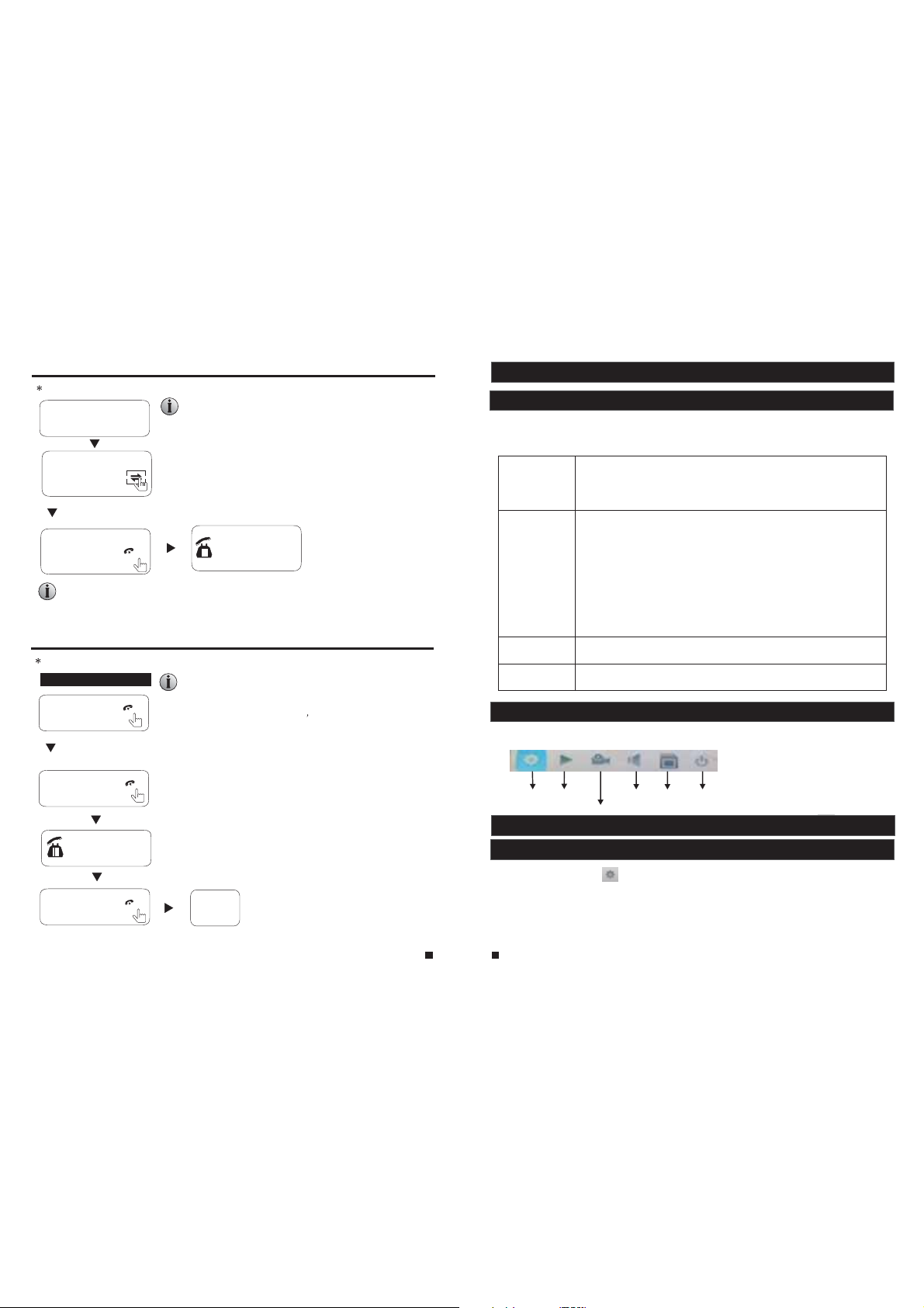
2.2 Tool Bar
Single-click the right-hand mouse button, and it will display the following toolbar.
Setup P laybac k Ring Rem ove SD Reboot
2.3 Tool Bar Menu Options
2.3.1 Setup
After c lickin g this but ton “ ”, a scr een for co nfigur ing all sy stem set tings wi ll appea r. From
this screen, system, video playback, scheduling, alarm, maintenance, us er and def ault
information can be adjusted.
1. In liv e view, righ t-clic king wil l either d isplay o r hide th e toolbar.
2. From t he main me nu or a sub- menu, ri ght-cl icking w ill exit t he curre nt
menu.
3. In vid eo playb ack, rig ht-cli cking wi ll eithe r hide or di splay th e contr ol
bar.
1. In men u unlock m ode, lef t-clic king on th e SETUP ic on in the tool bar
will open the main menu.
2. After en tering t he main me nu, left -click ing will o pen sub- menus.
3. By lef t-clic king, yo u can sele ct value s in edit bo xes or pul l-down menus.
The sys tem supp orts the i nput of Ch inese ch aracte rs, and ot her special
symbo ls, numb ers, and l etters .
4. Left -click ing can be u sed to acc ess the co lor cont rol bar, the volume
contr ol bar, and th e screen c ontrol b ar.
5. From t he main me nu, sub- menus, o r playba ck view, lef t-clic king “x” w ill
exit th e curren t menu.
6. Left -click ing can al so be used t o select m enu item s.
In live view or video playback, double-clicking will maximize the screen.
In the mo tion det ection s etting i nterfa ce, you ca n left-c lickin g and then d rag
the fra me to set th e motion d etecti on area.
Stop recording
13
14
Page 9

Note:
1. If the re is no “ ” but ton in the s ub-men u, in orde r to for cha nges to su b-menu s etting s to
take ef fect, it i s necess ary to ret urn to the “ save” me nu to clic k “ ”. Changes to the sub-menu
setti ngs will n ot be save d if you do no t click “ ” an d exit the s ub-men u immedi ately af terwar d.
2. If the re is a “ ” butt on in the su b-menu , users ne ed to clic k the “ ” butt on to
save parameters in the current window.
.A special f eature o f this dev ice is tha t an expla nation o f each menu item will be displayed
3
autom atical ly when th e cursor i s moved ov er it.
2.3.2 Manual Recording
There are two ways of recording live video/audio feed from your cameras: manual recording and
scheduled recording.
If scheduled recording is in conflict with manual recording, the manual recording will be
processed first until stopped.
For a det ailed description of scheduled recording, see
In order to manually record a video/aud io feed, c lick th e “ ” button fr om the “Tools” menu.
Click ing “ ” agai n will sto p the reco rding pr ocess.
Section 2.4.3 Record Scheduling.
2.3.3 Video Playback
To start video playback, first move the cursor to “ ” (the icon wi ll be high lighte d when sel ected)
and lef t-clic k it to ente r the sett ings men u. And left- clicki ng the “x” b utton wi ll exit th e curre nt
window, or move the cursor to the ““x” button and left-click it to exit.
Input t he date an d time, cl ick “ ” and th e record ing status on that date will be displayed. The
calendar on the above figure will show all the recordings in a given mont h. A backgroun d on the
calendar indicates that there was recording on the day. Click any date in t his fram e to searc h by
the rec ording f iles of th at day, and th e search r esults w ill be sho wn in the fi le frame .
On the file list, “Channel” shows which channel the file was recorded u nder, “Time ” shows th e
recor ding tim e, and “Si ze” is the s ize of thi s file (li sted in MB). An orange list indicates this
recor ding fil e is a motio n detect ion reco rding fi le, and a bl ack list i ndica tes this f ile is a nor mal
recording file.
Move th e cursor u p or down to s elect th e files, l eft-cl ick to ent er the pla yback me nu. It wil l play the
video f rom a single channel in full-screen view. When the selected files finish, the sc reen wil l
retur n to the fil e list men u.
Click ing “ ” butt on to ente r into the f irst pag e, click ing “ ” butt on to previous, clicking “ ” butt on
to the ne xt page, a nd click ing “ ” to the l ast page .
Note:
1. Afte r moving t he curso r up or down a nd selec ting the f iles, left-click to enter the playback menu.
It will p lay the vi deo from a s ingle ch annel in f ull-screen view.
15
2. When t he selec ted file s finish , the scre en will re turn to th e file lis t menu.
Playback Control
In play back mod e, users c an view th e playba ck contr ol panel a s well as th e date an d time of th e
file being played.
The fol lowing a re the fun ctions o f and opti ons for th e
items in the playback control panel:
Play
Pause
Minim ize the co ntrol pa nel.
Exit fr om playb ack and re turn to th e former
menu.
2.3.4 Ring Setting
Sin gle Cli ck “ ” on the t ool bar m enu to en ter the “ Ring setting”menu.
[Ring]: Cli ck the ic on “ ” on the right
sid e of the op tion to a djust t he ring t ype.
[Volume]: To set u p the v olu me of t he ri ng,
val ues can b e set fro m 15 to 30.
[Ring time]:To set up th e ring ti me of the
rin g, valu es can be s et from 5 s econd s to
30 seconds.
[Unlock time]: Optio ns can be s et up fro m
1 second to 10 seconds.
2.4 Menu Options
In orde r to modif y or adjus t the syst em confi gurati on, it is ne cessar y to enter t he “Setu p” menu; t o
do this , click th e “Setup ” icon ( ) in th e “Tools” Menu .
After c lickin g the “Set up” icon , a dialog b ox with se ttings f or all of th e system s and opti ons
available for the device will appear. The settings are divided into nine subsections: “System”,
“Playback”, “Network”, “Scheduling”,
“Alarm”, “Maintenance”, “User”,
“Default” and “Information”. The
following are detailed descriptions of
these s etting s.
2.4.1 System
Move th e cursor t o the “Sys tem” ico n and
left- click to e nter the “ System ” menu. Sy stem
setup i nclude s: “Basi c config ure” and “ Time”.
16
Page 10

2.4.1.1 System-Basic
Basic configure includes: “Language”, “Standard”, “Color Setup” and “Vid eo margi n”.
[Standard]: From th is field , select t he syste m output t ype that i s consis tent wit h camera i nput,
i.e. PAL or NTS C.
[Language]: Use this field to change the language of the device menu text and the on-sc reen
display.
[Color Setup]
Click “ ” t o enter th e “Color S etup” me nu. From
this menu, the video color attributes can be adjusted for
the best image quality. By default, the values are set at
31, as this is the median value. Make adjustments to
the chr oma, bri ghtnes s, contr ast, and /or satu ration a s
appro priate d ependi ng on the ac tual con dition s at the
location where the camera is installed.
Click the vertical bar on the slide bar and drag the cursor to the left o r right a long the s lide bar t o
set color attributes. Once the color attributes have been set, click “ ” to sav e the sett ings.
[Video Margin]
Click “ ” to enter the “ Video Ma rgin” me nu, the en tire vid eo scree n can be mov ed up,
down, t o the left , and to the r ight usi ng this op tion.
2.4.1.2 System-Time
2.4.2 Network
Move th e cursor t o the “Net work” ic on and lef t-clic k to enter t he “Network” menu. Network setup
includes: “Basic Setup”, “Port” and “Advanced”.
2.4.2.1 Network-Basic
[Network Link]: There are three options: “Static” and “DHCP”.
After selecting an Internet connection setting - such as st atic or DHCP – and al locati ng a port,
users c an acces s the devi ce remot ely via th e Intern et.
1)If sta tic allo cation h as been se lected , it is nece ssary to s et up an IP address, a subnet mask, a
gateway, and a Web port .
[IP Address]: Enter the IP address in this field.
[Subnet Mask]:Input numbers for the subnet mask.
[Gate way]: En ter numb ers for th e defaul t gatewa y.
[DNS Add ress]: I nput num bers for t he subne t mask in th is field .
2)If DHC P is selec ted, the s erver wi ll alloc ate an ind oor unit I P address automatically.
NOTE:
Save th e IP addre ss when se lectin g DHCP and th e indoor u nit will automatically connect
with th e server. It w ill allo cate an IP a ddress w hen the co nnecti on is stab le, and th is addre ss will be
displ ayed on th e interf ace.
2.4.2.2 Network-Port
[Date Format]: Left-click to switch the date format, include YY/MM/DD, MM/DD/YY and
DD/MM/YY.
[Date]: Left -clic k to swit ch the nu meric al keyp ad, and s et the da te using the numerical keypad.
[Time Format]: Lef t-c lic k to sw itc h the t ime f orm at fr om a 12 -ho ur cl ock t o a 24- hou r clock
and v ice ver sa.
[Time]: Lef t-c lic k to sw itc h the n ume ric al ke ypa d, an d set t he sy ste m time using the numerical
keypad.
17
18
Page 11

[Media Port]: Port fo r the pri vate pr otoco l of the de vice an d compu ter; th e defau lt is “90 00”. If
thi s port is b eing us ed by oth er serv er, use an other f ree por t for the device.
[We b Por t]: S ets u p a Web browser port via HTTP. The default port number is “8090”, but the
specific number is model-dependent. If Administrator changes the Web p ort , for e xam ple ,
“8088”, the port number should be added after the IP address, i.e. http://192.168.15.145:8088
should be entered as the IP address of the Web browser.
[Setup Port]: It's used to control the device. The default number is “8000”. User c an sp eci fy a
different port number.
2.4.2.3 Network - Advanced
In adva nced men u, user ca n set up DDN S, Wifi, U PNP, Mobile ph one, Sub S tream an d
IP firewall.“ ” indicates the selected option is enable. Click “ ” to enter i nto the ne xt page,
and cli ck “ ” to the pr evious .
User should enable the relevant function with “ “ befor e setup.Note:
A. DDNS
”indicates DDNS is enabled. Move the cursor to “DDNS” (the tab will be highlighted when
“
selected) and single-click to enter the D DNS setu p menu.
[Server]: There are three options: “3322”, “dyndns” and “easterndns”.
[Host Name]: In this f ield, e nter th e name of t he host s erver.
[User Name]: In this field, enter the username.
[Password]: In thi s field , enter t he pass word.
B. Wifi (Optional)
For the indoor unit with W IFI f unc tio n, us ers c an vi sit t he de vic e rem ote ly by t he fo llo wing
methods: through network cable connection or through wireless connection. If through wireless
connection, please setup the parameters about Wifi manually. indica tes Wif i is enab led.
Mov e the cur sor to “W ifi” (t he tab wi ll be hig hligh ted whe n selec ted) an d singl e-cli ck to ent er
the W ifi set up menu .
Not e: Thro ugh W ifi c onn ect ion , the “ Net wor k Type ” on th e Net wor k Basic interface suggested
to be set as “DHCP”. When configure the parameters about WIFi, use r can e nte r the n etw ork
bas ic inte rface t o view th e indoo r unit ca n be allo cated I P add res s whe the r or no t. If n ot, u ser
mus t set up pa ramet ers abo ut Wifi a gain.
“ ”
[SSID]: Input t he effec tive wir eless ro uter SSI D.
[Password]: If the password of the wireless router is enabled, the option should be a djusted to “ ”.
[AuthMode]: Options include “WPA-PSK” and “WPA2-PSK”.
[EncrypType]: Optio ns inclu de “AES” a nd “TKIP ”.
[Key]: Input the p asswor d of the wir eless ro uter.
C. UPNP
“ ”indi cates UP NP is enab led.
D. Mobile Phone
Mov e the cur sor ove r “Mobi le Phon e” (the t ab will b e highl ighte d when selected), and single-click
to en ter the m obile s ettin gs menu .
[Phone port]: Mobi le moni torin g port. I n this fi eld, en ter the r eleva nt mobi le port . The r ang e
for s erver p orts is b etwee n “1024 ” and “65 535”. T he de fau lt is “10510”.
[Push time(s)]: From t his fie ld, sel ect pus h tim e for mot ion d etect ion or vi sitor calling.
[Push]: “ ” indic ates th e push fu nctio n is to be en abled .
E. Sub Stream
Mov e the cur sor ove r “Sub St ream” ( the tab w ill be hi ghlig hted when selected), and single-click
to en ter the S ub stea m menu.
19
20
Page 12

[Channel]: After c licki ng the “C hanne l” tab, u sers ca n modif y the set tings of the camera
connected to the selected channel. Users can modify the parameters of each channel
independently.
[Frame rate]: For th e PAL vid eo outp ut form at, opt ions in clude 5 -25 fra mes. Fo r the NTS C
video output format, options include 5-30 frames.
[Bit rate]: The re ar e 5 opt ion s: 64 K, 12 8K, 1 92K , 256 K and 3 84K .
[Bi t rate co ntrol ]: Ther e are t wo mo des f or bi t rat e con tro l: VB R and C BR
CBR mode, the video encoder will encode according to the bit rate yo u hav e sel ect ed. I f use rs
choose VBR mode, the video encoder will consider to the image quality and encode according
to th e bit rat ed have b een sel ected , but not s trict ly acco rding t o this bi t rate. S ugges t VBR mod e.
F. IP Firewal l
Mov e the cur sor ove r “IP Fir ewa ll” ( the i con w ill b e hig hli ght ed wh en se lec ted ), an d sin gle -cl ick
to en ter the I P Fir ewa ll me nu.
The options for IP access settings are: “disable”, “Black list” and “ Whi te li st” .
. If us ers cho ose
2.4.3 Record Scheduling
Click Setup”—“Scheduling”(the tab will be highlighted when selected) and single-click to enter
the “Record Scheduling” menu.
[Channel]: Use rs can se lect ch annel 3 o r chann el 4.
The re are th ree mod es for re cordi ng: “MD ”, “Nor mal”, “ None” . Different colors are used to
identify the different recording modes: Orange refers to “MD record”, green refers to “normal
rec ord”, g ray ref ers to “n o recor d”.
To set up weekly schedules, click on the box of the recording stat us to b e use d (Al arm , Nor mal ,
or No record) and then click on each box in the schedule timeline th at th is re cor din g sta tus i s to
be applied to. See the “Scheduling” screenshot in the preceding fig ure. Ea ch gray b lock
rep resen ts one ho ur on a 24-hour clock, i.e. the first block(next to each day of the week)
rep resen ts the ho ur from m idnig ht-01 :00 AM and t he last b lock (b elow th e “23” on t he righ t hand
side of the screen) represents the hour from 11:00 PM-midnight. Aft er se tti ng up t he re cor d
schedule, click the “ ” butto n at the bo ttom of t he scre en to sav e it.
Alternatively, left-click and drag the frames of the boxes in the sc hed ule t ime lin e whe re yo u
want to.
Ano ther wa y to set up s chedu les is to c reate a s chedu le for on e day of th e week, a nd then u se
the “ Copy fr om” and “ to” dro pdown m enus an d “ ” copy bu tton se tting s to appl y the
set ting fr om one da y to anot her day o r a series of up to all seven days of the week. To do this,
fir st crea te a schedule for one day. Then, from the “Copy from” dropdown menu, selec t the f irs t
day o f the wee k that th e sched ule sho uld app ly to. Ne xt, fro m the “to” dropdown menu, select
the l ast day o f the wee k that th e sched ule sho uld app ly to, an d click “ ” c opy but ton. Fo r
exa mple, t o set a sch edule w here th e devic e uses MD r ecord ing fro m 2:00 AM un til 1:0 0 PM,
and normal recording from 1:00 PM until 10:00 PM on Tuesdays, Wednesdays, Thursdays, and
21 22
Fridays, the process would be as follows:
1. Cl ick the o range b ox at the b ottom o f the scr een to se lect “MD record.” Then, in the row of
gra y boxes n ext to th e “TUE. ” box, cl ick all o f boxes f rom the t hird bo x from th e left to t he box
und er the “1 2” at the t op of the t imeli ne(th e box dir ectly u nder th e “12” sh ould be s elect ed) in
ord er to sel ect the h ours be tween 2 :00 AM and 1 :00 PM.
2. Cl ick the g reen bo x at the bo ttom of t he scre en to sel ect “normal record.” Then click all of
the b oxes in t he same r ow from t he box im media tely to t he righ t of the bo x under t he “12” a t
the t op of the t imeli ne to the t hird bo x from th e right t o selec t the hou rs from 1 :00 PM- 10:00 P M.
3. Th e pre ced ing s tep s set a s che dul e for Tu esd ay, wh ich c an no w be co pie d to We dne sda y,
Thu rsday, a nd Fr ida y. To copy it , from th e “FROM ” field , first select “Tues.”
4. In t he “To” fie ld, sel ect “Fr i.” and t hen cli ck “ ” copy b utton .
5. To sav e thi s sch edu le, c lic k the “ ” b utt on at t he bottom of the screen.
Regardless of whether the schedule is set for each day individually or by copying one schedule
to multiple days of the week, it is necessary activate it by click ing t he “ ” bu tto n. Wi tho ut
cli cking t he “ ” the sc hedul e will no t take ef fec t.
2.4.4 Alarm
Click “Set up”—“ Alarm ”(the t ab will b e highl ighte d when se lecte d) and si ngle- click t o enter
the “ Alarm ” menu. An d the dia log win dow whe re Sens itivi ty, MD Area , Ena ble S wit ch an d
record settings can be set will appear.
[Channel]: In th is fiel d, sele ct the ch annel t o be set up .
[Sensitivity]: Eac h chann el has a sp ecifi c sensi tivit y setti ng; the re are ei ght lev els, wi th “1”
bei ng the hi ghest l evel of s ensit ivity ; left- click ing to ad just the level.
[MD Area]: Som eti mes , it is n ece ssa ry to h ave s ome
regions in the camera's coverage area enabled with
the m otion d etect ion fea ture, w hile ot her reg ions in
the s ame cov erage a rea do no t requi re this
fun ction ality. T his m ay be h and y whe n, fo r exa mpl e,
the c amera c overs t he road a nd an adj oinin g area.
While it would be useful to have the motion detection
ena bled on t he area n ear the e ntran ce to a bui lding , it
wou ld most l ikely n ot be hel pful to s ee it tri ggere d
every time a car or tr uck pas ses by on t he nearby
roa d. Each c hanne l has a specific regional motion
detecting setting.
Mov e the cur sor to “ ” an d then si ngle-click.
When viewing the selected channel's coverage area
usi ng the MD Ar ea opti on, the b lue are a is wher e motio n detec tion is a ctiva ted, an d trans paren t
blo ck is the a rea whe re moti on dete ction i s not act ivate d.
Lef t-cli ck and dr ag the fr ame to se t up the re gion fo r motio n detection.
[MD Enable]: Each c hanne l has a cor responding channel switch. “ ” indicates that the motion
det ectio n alarm o f the sel ected c hanne l is enab led.
[Record]: “ ” indi cates t hat the s elect ed chan nel wil l recor d if it has b een tri ggere d by moti on.
Not e: To sele ct th e opt ion , ple ase m ake s ure t hat a S D car d has been already inserted
int o the vid eo data c an be sto red ont o the SD ca rd norm ally.
2.4.5 Maintenance
Click “Set up”—“ Alarm ”(the t ab will b e highl ighte d when se lecte d) and single-click to enter the
“System Maintenance” menu. Options include “SD Management” and “System Upgrade”.
Page 13

2.4.5.1 SD
To enter the “S ystem Ma intena nce”, se lect “SD ” (see adj acent fi gure).
[Size/Free]: This field indicates amount of space available and the amount of un use d spa ce
available on the SD card.
[Free Time]: Indicates remaining recording time on the SD card.
[State]: The re ar e thr ee av ail abl e sta tus es: “ OK” a nd “N o SD” .If a n ew SD c ard i s use d wit h
the device for the first time, please format the SD card.
[Format]: Mov e the cur sor to se lect th e devic e to be for matte d, “ ” indi cates t he opti on of
“format” is enabled, and click “ ” to beg in fo rma tti ng.
[Auto overwrite]:Opti ons Inc lude “D isabl e and Auto ”. If a use r chooses “Disable”, the
rec ordin g stops w hen the S D card is f ull. On ce the SD c ard is fu ll, it wi ll not re cord ag ain unt il
“ov erwri te” is en abled . If a user c hoose s “Auto ”, reco rding c ontinues and overwrites previous
rec ordin g when th e SD card i s full.
2.4.5.2 Upgrade
To enter the “system Maintenance”, select “upgrade”(see adjacent figure).
Cre ate a new r oot dir ector y calle d “ivru pgrad e” on a SD ca rd, cop y the upd ate fil e to it,
and then insert it into SD port of the device. Click “ ” to upgrade the firmware and it
will display the process of the system upgrade.
Note: The syst em up gra de wi ll re qui re at l eas t two m inu tes ; durin g this ti me, d o not rem ove the
SD card or turn the device disable. After completing the upgrade, the de vice wi ll rest art.
2.4.6 User
Click “Setup”—“User”(the tab will be highlighted when selected) and sing le-cl ick to en ter
the “ User” m enu. In t his fie ld, a pas sword f or acce ssing t he devi ce syst em can be c hange d.
Fro m this wi ndow, th e Administrator can change the system's password. For security reasons,
bef ore a new p asswo rd can be s et, it is necessary to enter the original password. Click “ ”
to save.
2.4.7 Default
Click “Set up”—“ Defau lt”(t he tab wi ll be hig hligh ted whe n selec ted) an d singl e-cli ck to ent er
the “ Resto re to def ault” m enu.
The s ystem r estor es the de fault c onfig urati on stat us in the f actor y, and c orr esp ond ing s ett ing
can b e resum ed base d on opti ons on th e menu. U ser can s elect “ All” to r estor e all the s ettin gs
to th e origi nal fac tory se tting s. The op tio ns in clu de: Ti me, C olor and margin, Record schedule,
Use r, Maint enanc e, Netw ork, Ne twork a dvanc ed and Ala rm setu p.
Prompt: The port and language can't be resumed.
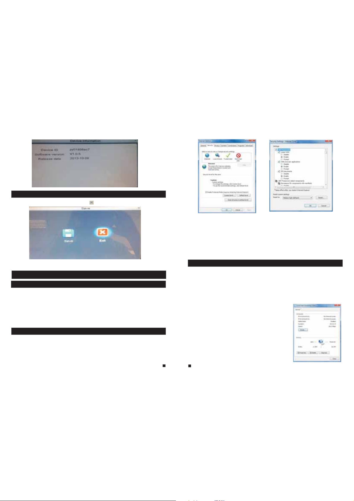
2.4.8 Information
Click “Setup”—“Information”(the tab will be highlighted when selected) and single-click to enter
the “Device information” menu.
The information included accessible through this interface includes : the d evi ce ID , the
sof tware v ersio n and the r eleas e date.
23
24
Page 14
2.4.9 Save/Exit
On the “Configuration” menu, right-click or click “ ” to enter the “ Save” me nu.
[Save]: Sav e all set tings a nd exit t he menu .
[Exit]: Exit the menu without saving any changes.
3. Web Browser Operation
3.1 Feature
Install the software through the Internet browser of OS to conveniently operate the network
fro m a remot e locat ion. Th is device supports C/S, B/S, and access in LAN and WAN. It also
supports IP and domain name visiting.
IMPORTANT! SOFTWARE RECOMMENDATIONS:
To ensure reliable remote viewing of IVR footage, it is highly recommended that users have
either Windows XP, Windows 7 or Wind ows 8 ins talle d on thei r compu ters, a nd that t hey use
either Internet Explorer 6.0, Internet Explorer 7.0, Internet Explorer 8.0, Internet Explorer 9.0,
Moz illa Fi refox , or Goog le Chro me as the ir Inte rnet br owser. ( In the ap pendi x, ther e is an
explanation of how to access the indoor unit using Firefox or Google Chrome.)
3.2 Network Security Setting
Pri or to set ting up r emote a ccess , set the n etwor k secur ity lev el by fol lowin g the fol lowin g
instructions:
(1) O pen the I ntern et Expl orer br owser a nd clic k the “Tool s” tab lo cated i n the bar a t the top
of the browser; from the drop-down menu, select “Internet Options”.
(2) C lick th e “Secu rity” t ab in the d ialog ue box
(3) C lick “C ustom l evel” ( at the bo ttom of t he dial ogue bo x) to set t he secu rity le vel. .
Set the appropriate settings for the ActiveX controls and plug-ins. Find the following controls
in the “Security Settings” box and select the “Enable” option for eac h of them . Thi s is an
extremely important step.
* Automatic prompting for ActiveX controls.
* Bin ary and s cript b ehavi ors.
* Ini tiali ze and sc ript Act iveX co ntrol s not mar ked as sa fe for scripting.
* Download signed ActiveX controls.
* Dow nload u nsign ed Activ eX cont rols.
* Run ActiveX controls and plug-ins.
* Script ActiveX controls safe for scripting.
Prompt: Before setting up remote access, turn Disable the firewall an d any ant i-vir us soft ware
cur rentl y runni ng on the c omput er.
3.3 Connection Settings
Rem ote acc ess to th e IP vide o doo r pho ne is c arr ied o ut ov er th e Internet. In the local area
net work, t he IP add res s of th e cli ent -si de co mpu ter m ust b e in th e sam e net wor k seg men t tha t
the IP address of the IP video door phone. In the wide area network, the only requirement is
that the two sides can visit the public network and connect to the Internet through the IP
address or the dynamic domain name. The following will mainly focus o n con nec tin g and
set ting up t he loca l area ne twork .
Step 1: Right-click on “Network Neighborhood” and click “Properties ” in th e men u to op en th e
“Network Connections” menu. Alternatively, if the operating system be ing u sed d oes n ot ha ve
a “Network Neighborhood” icon, enter the Control Panel found in the “St art” me nu; the n, clic k
“Ne twork a nd Inte rnet” , and sel ect “Ne twork a nd Shar ing
Cen ter.” On t he “Net work an d Shari ng Cent er” pag e, ther e
sho uld be a “N etwor k” sect ion; in t hat sec tion, t here sh ould be
a “Vi ew St atu s” li nk ne xt to a l ist ing t hat r ead s “Co nne cti on:
Loc al Area Co nnect ion.” C lick th e “View S tat us” l ink . A sma ll
“Lo cal Area C onnec tion St atus” w indow w ill app ear; at t he
bot tom of th is scre en, cli ck “Pro perti es”, an d if prom pted to
giv e permi ssion t o conti nue, cl ick “Yes .”
Ste p 2: Doub le-cl ick to op en “Loc al Area Co nnect ion” fr om the
“Network Connections” menu.
Step 3: Click “Properties” in the lower-left corner of the window
(see preceding figure).
Ste p 4: Doub le-cl ick “In terne t proto col (TC P/IP) ” from th e “This
con necti on uses t he foll owing i tems” l ist in th e cente r of the
window (see preceding figure).
25
26
Page 15

Step 5: Examine the IP address, subnet mask, and default gateway on the P C.
Step 6: Set the corresponding IP address, subnet mask, and default ga tew ay on t he in doo r
unit(for detailed instructions, refer to ). If the subnet mask and
def ault ga teway o n the ind oor uni t are the s ame as th ose of th e compu ter, the n the IP ad dre ss
is mo st like ly in the s ame net work se gment . Howev er, they m ust not b e exact ly the sa me as
the ones on the indoor unit, as this will cause IP address conflict s. Taki ng th e pre ced ing f igu re
as an e xampl e, the IP a ddr ess s hou ld be : 192 .16 8.1 .X, w her e X can not b e 244 o r 1 (in clu din g
oth er IP add res ses c urr ent ly be ing u sed ), an d can not e xce ed 25 5, as t he su bne t mas k is
255.255.255.0, and the gateway is 192.168.1.1.
3.4 Control Download and Installation
Aft er the af oreme ntion ed sett ings ha ve been a djust ed and sa ved, op en the In terne t brows er,
http://192.168.1.X
ent er (19 2.168 .1.X is t he set IP a ddr ess o f the i ndo or un it) a nd co nfi rm. I f
the h ttp por t of indo or unit s ettin g has bee n chang ed (if it i s not “80 ”), it wi ll be nec essar y to
add a “ :” followed by a port number. F or exam ple, as sumin g that th e curre nt port n umber i s “P”,
ent er “ ”, to c orrec t the pro blem.
http://192.168.1.X:P
After connecting to the internet, Internet Explorer (or other Inter net bro wser be ing use d) will
aut omati cally d ownlo ad the fi le to the c omput er as fol lows. C lick “Install”.
The system will automatically enter the GUI as follows.
Section 2.4.2 Network Setup
Sel ect the E nglis h inter face fr om the up per lef t side. E nter th e corre ct pass word if a p asswo rd
has b een ena bled. T he pa ssw ord i s the s ame a s the o ne se t in in door unit.
[US ER ID]: In this field, enter the username. The default is Admin.
[PASSWORD]: The p ass wor d is as t he sa me as t he pa ssw ord f or th e ind oor u nit . The de fault i s
888888.
[NETWORK]: MA IN STRE AM or SUB S TREAM .
[Op en Prev iew]: “ ” enable to view all the cameras automatically after the login. “ ” means
tha t user ne eds to co nnect a ll the ca meras m anual ly afte r the login.
Note: If the device is connected to the WAN, the IP address should be a p ubl ic IP ad dress .
3.5 Operation Interface
Opt ions in t he main i nterf ace inc lude “L IVE”, “ PLAYBA CK” , “RE MOTE SETTING”, “LOCAL
SETTING” and “LOGOUT.” Click any option to access it.
3.5.1 Live
Click “Live” to enter the interface as follows (in some cases, it wi ll be n ece ssa ry to c lic k “ ”
to op en imag es from t he indo or unit ).
27
28
Page 16

The l eft bot tom cor ner of ea ch indi vidua l chann el is occ upied b y camer a view to ols:
/ :Connect the current window view or close the current window view.
:Sta rt reco rding o r stop re cordi ng of the c urren t chann el view. An d the rig ht bott om
/
cor ner of th e curre nt chan nel has a n ormal r ecord ing vid eo symb ol “ ”.
:Takes a s napsh ot of the d isplayed image.
:Increase or decrease brightness.
:Increase or decrease image contrast.
: This indicates that the channel has detected motion while in motion-detection mode of
the r emote i ndoor u nit.
:Unlock for the door machine. Click this button to access the “Unlock” window(shown as
below), input the correct password and click the button “ ” to confirm .
3.5.2 Controls
To use t he co ntr ols , mov e the c urs or ov er th e ico ns, w hic h wil l become highlighted
when selected.
Connect all windows or disconnect all windows.
/
Capture images which can be saved in a loca l dis k (th e def aul t sys tem s ave p ath i s
“c:\IVR\Capture\”).
Qui ck-st art to re cord vi deo on al l chann els, an d the rig ht bott om corn er of eac h chann el
has a n ormal r ecord ing vid eo symb ol “ ”(th e defau lt syst em save p ath is
“c:\IVR\Record\”).
Click t his butt on to talk w ith the do or machi ne. And clic k it again t o stop.
Click this button to unlock for the door machine.
Click these icons to switch between the single-screen ( ), qua d-s pli t( ) an d ful l-s cre en
( ) opt ions.
Cli ck on the v ertic al bars t o adjus t the vol ume.
3.5.3 Other Operations
1.Select one channel from the preview screen (the color of the sele cte d cha nne l's f ram e wil l
change to blue), and double-click the left mouse key will enlarge the c urren t chann el view.
And single-click right mouse key as a full -sc ree n dis pla y of th e sel ect ed ch ann el.
2.Single-click right mouse key on the preview screen will maximize all t he curr ent cha nnels t o
full-screen. And single-click right mouse key again will back out.
3.5.4 Playback
Click “Playback” to enter the playback interface.
To sear ch for a re cordi ng by dat e, clic k calen dar in th e upper -righ t corne r, and use “ ” and
“ ” to se t the mon th of the v ideo be ing sea rched f or; cli ck “REFRESH” (located just below the
calendar) to display the recording information of current month.
The h ighli ghted d ate ind icate s the rec ordin g date of t he vide o being played. Click on a date t o
vie w the rec ordin g file li st for th at day. Fo r exa mpl e, th e pre ced ing f igu re sh ows t hat t her e are
videos on file that were recorded on November 5 and 7 (indicated by the nu mbers b eing in
bold print), and is the recording file list that is currently open is the list of videos recorded on
November 5 (indicated by the darker background and the “5” in white text).
Ano ther wa y to find a v ideo is t o selec t the cha nnel an d type of t he file i n quest ion fro m the fil e
lis t below t he cale ndar. Aft er sele cting t he chan nel and t ype from their respective drop-down
men us at the t op of the f ile lis t, clic k “SEAR CH” and t he resu lts wil l be disp layed i n a list li ke the
one in the following figure.
th
th th
29 30
Page 17

Double-click one of the listed recorded videos or select one of the lis ted rec orded v ideos a nd
the n click “ PLAY” to b egi n pla yba ck.
Usi ng this b utton , users c an down load fi les to th eir com puter s and sav e them to a
HDD f or back up or lat er view ing. Th e dow nlo ade d fil e for mat i s “AVI”. The option“ ” on the l eft
sid e of the fi le is ava ilabl e for dow nload ing. “ ” in dicat es the fi le will b e saved t o a HDD aft er
cli cking t he “ ” butt on.
3.5.5 Toolbar Guide
Play status bar
Play Pause St op Fast play Sna p E-zoom
Slow Play Single Frame
Download st atus bar
The starting time and the ending time of the current downloading file
Volume
Control
3.5.6 Remote Setings
Click “Remote Setting” to enter the “Remote Setting” setup menu. This i nte rfa ce in clu des
record setting, alarm setting, network setting, advanced setting, system info, remote upgrade
and user modify, whic h can all b e modif ied rem otely t hroug h an Internet browser.
A.Record Settings
In the sidebar on the left, click “Record Setting” to enter the reco rdi ng se tti ngs m enu . Fro m thi s
page, users can enable or disable recording for channel 3 or cha nne l 4, se t rec ord ing s che dul es,
and adjust specific recording parameters, i.e. enabling/disabling aud io, s ett ing t he pa ck ti me,
and setting recording modes.
B Ala rm Se tting s
Fro m the sid ebar on t he left , click “ Alarm S ettin g”, the n selec t “Chan nel Alar m” to ent er the
“Ch annel Al arm” se tup int erfac e. From t his int erfac e, user s can set motion-detection alarms,
define motion-detection privacy masking areas, motion sensitivit y, and r eco rd du rat ion .
C Network Settings
Fro m the sid ebar on t he left , click “ Netwo rk Sett ing”, a nd then s elect “ Netwo rk” to en ter the
network settings interface. The menu allows users to set basic att rib ute , PPP OE an d DDN S
setup.
D Mobil e Set tings
Fro m the sid ebar on t he left , click “ Netwo rk Sett ing”, a nd then s elect “ Mobil e” to ent er the
“Mo bile Se tting s” inte rface . From th is page , users c an set po rts, pu sh swit ch and pu sh time .
31
32
Page 18

E IP Firewall
From the sidebar on the left, click “Network Setting”, and then s ele ct ”I P Fir ewa ll” t o ent er th e
firewall settings interface. From this page, users can turn the fire wall on o r Disab le for sp ecifi c
IP addresses.
H. REMO TE UP GRADE
Fro m the sid ebar on t he left , click “ REMOT E UPGRA DE” to en ter the r emote u pgrad e inter face.
Cli cking “ ” w ill sel ect fil e for upg radin g. Then c lic k the “ ” r emo te up grade
but ton in th e cente r of the sc reen.
F System Setti ng
From the sidebar on the left, click “Advanced Setting”, then select “S ystem S ettin g” to ent er
the system settings menu. From this menu users can find out the lan gua ge an d TV mo de fo r the
indoor unit.
G System Info
[Version Information]: From the sidebar on the left, click “System INFO”, and then select
“Ver sion IN FO” to en ter the s ystem i nform ation i nterf ace. He re, use rs can fi nd out th e devic e
nam e, soft ware ve rsion , and the r eleas e date.
33 34
I. User Management
[Modify password]: From t he side bar on th e left, c lick “U ser Man ager” , and the n select “Modify
pas sword ” to ente r the use r manag ement i nterf ace. Us ers can m odify the user’s password.
3.5.7 Local Setings
Fro m the sid ebar on t he top, c lick “L ocal Se tting ” to ente r the loc al sett ings in terfa ce. Fro m this
pag e, user s can set u p the sav e path fo r local s ettin gs; in th e “Reco rd Save P ath” fi eld, th ey can
cre ate a sav e path fo r recor dings , in the “P ictur e Save Pa th” fie ld, the y can cre ate a sav e path
for v ideo/ still i mages , and in th e “File S ave Pat h” they c an crea te a save p ath for d ownlo ads.
Cli cking “ ” w ill set u p the res pecti ve save p ath.
Page 19

3.5.8 logout
Click “Logout” to log out of the system.
4. Mobile Phone Software Visit
Thi s IP vide o doo r pho ne ca n tra nsm it li ve fe ed to y our m obi le ph one , so th at yo u can h ave ' on
the go' access to your surveillance system from virtually anywhere . To view, y ou mu st in sta ll a
mobile operating system specific program into your mobile. Curre ntly, th ere a re a limited
number of phones that are supported: Google Android and Apple iPhone or iPad. The Android
mobile program is located on the included CD or downloaded via “Play Store”, and an iPhone
mobile program or an iPad program is downloaded via “APP Store”. In “APP Store” or “Play
Store”, please search for “MobileEyeDoor”. Please see the instru ction m anual f or your m obile
to install the program.
4.1 Iphone Mobile or Ipad
The Apple iPhone or iPad application, like all iPhone or iPad appl ica tio ns, n eed s to be
downloaded directly from the App Store. Open APP store, search for “ Mobil eEyeD oor”, i t's a
free application.
(1) “MobileEyeDoor” installation
Acc ordin g to the fo llowi ng meth od, ope n the App st ore “ ”, to uch “ ” and s earch f or
“MobileEyeDoor”. Install it on the mobile phone or the iPad. After installing “MobileEyeDoor”,
it will appear a “ Mo bil eEy eDo or” i con o n the a ppl ication software.
How to use “MobileEyeDoor”
(2)
1>
Click the “MobileEyeDoor” icon to run the program. Click “ ” t o add a new d evice , first
please choose the adding type, there are there methods to add dev ice : “QR C ode S can ”,
“Manual” and “Local Search”.
A. Adding by “QR Code Scan”
Click “ ” to th e next in terfa ce, use rs can scan two-dimensional code attached
to th e machi ne thro ugh the m obile p hone or t he iPad , and the d evice U ID will b e shown .
B. Adding by “Manual”
Click “ ” to th e next in terfa ce, use rs can ad d a new dev ice by UI D type or b y IP type .
a.By UI D type
Aft er ente ring th e “UID Typ e” Se tti ngs m enu , the f oll owi ng fi eld s wil l nee d to be c omp let ed:
Name: Set na me for th e indoo r unit, a nd save s setti ngs for f uture u sage.
UID: The device UID (UID is attached to the machine).
User: The us er na me se t for e nte rin g the i ndo or un it sy ste m. Th e def ault is “Admin”.
Password: The p ass wor d set f or en ter ing t he in doo r uni t sys tem . The d efault is “888888".
Channel Number: S et th e max c han nel s of th e dev ice w ill b e con nec ted .
Cli ck “ ” to save.
b. By I P typ e
Cli ck “IPTy pe” to en ter the S ettin gs menu , the fol lowin g field s will ne ed to be co mplet ed:
Name: Set n ame for t he indo or unit , and sav es sett ings fo r futur e usage.
Address: The public IP address or dynamic domain name of the indoor unit.
Port: The m obi le po rt of t he in doo r uni t for r emo te ac ces s vie win g via m obi le ph one , the
def ault is “ 10510 ”.
User: The u ser n ame s et fo r ent eri ng th e ind oor u nit s yst em. ( Adm in by d efa ult )
Password: The p ass wor d set f or en ter ing t he in doo r uni t sys tem . (88 888 8 by de fau lt)
Channel Number: Selec t the max c hanne ls of the d evice w ill be co nnect ed.
Cli ck “ ” to sav e.
C. Adding by “Local Search”
On LA N, turn o n the WIF I of the Wi reles s Route r and the m obile p hone( or the ip ad). Cl ick
“Lo cal Sea rch” an d onlin e devic es will a ppear o n the “Pl ease ch oose th e devic e” list , click
one t o add the d evice , the fol lowin g field s will ne ed to be co mpleted:
Name: Set n ame for t he indo or unit , and sav es sett ings fo r futur e usage.
User: The u ser n ame s et fo r ent eri ng th e ind oor u nit s yst em. ( Adm in by d efa ult )
35
Password: The p ass wor d set f or en ter ing t he in doo r uni t sys tem . (88 888 8 by de fau lt)
36
Page 20

Channel Number: S et th e max c han nel s of th e dev ice w ill b e con nec ted .
Click “ ” to sa ve.
2> After adding the device successfully, the device will appear on the main screen. Click the
dev ice, an d all the c hanne ls of the d evice w ill be sh own on th e screen. Click any channel and
it will connect immediately. The background of the channel will be hi ghl igh ted a fte r con nec tin g
successfully(shown as follows).
3> The functions of the other icons on the live view:
Unlock.
Snapshot .
of the channel has a no rmal recording video symbol “[REC]”. And click it again to stop manual
record.
Click i t to turn th e sound on o r disabl e.
Click i t to start t o talk, an d the back ground o f the butt on will be h ighlig hted. Cl ick it aga in to
stop talking.
Click i t to displ ay or hide t he butto ns “ ”.
Click i t to enter t he devic e list int erface .
Click i t to enter t he snaps hot file a nd record file.
Click i t to enter t he local setting interface.
Click i t to enter u ser guid e interf ace.
4> On the l ive view, us ers can to uch a chan nel on the s creen an d drag it to t he other c hanne l
postion directly.
5> On the interface of “Device”, user can edit the parameters of one device, c lick “ ” to th e next
inter face as be low. Click “ ” t o enter ed it mode to a djust the parameters. Click “ ” t o save.
And cli ck “ ” to remo ve the inf ormati on of the current device.
: to capt ure a fram e of the vid eo strea m as a still p hoto
Recor d: Click i t to start m anual re cord vid eo on the cu rrent ch annel, and the right top corner
mobil e phone ar e both con nected t o intern et.
Note: 1 )When th e option “ Alarm Se tting” o n the mobi le softw are inte rface is s et to “On” , and the
order “Configuration--Network--Advanced--Mobile Phone--Push” on the r emote in door uni t is
enabled. When someone press the call button on any outdoor camera, the ala rm
infor mation w ill be pus hed to the p hone. And us ers can cl ick the al arm lis t to acces s to the vid eo
live view of the channel directly or access to the video live vie w to unloc k for the ou tdoor ca mera .
2)The a larm pus h functi on can be ef fectiv e, and the d evice mu st be added by UID type.
6>
Click “ ” t o enter th e snapsh ot and rec ord file i nterfa ce. Clic k “Photo s” or “Rec ords” to s witch
displ ay inter face. Click “ ” t o enter ed it
mode, u sers can r emove th e file lis t that the y want to.
7> Clic k “ ”to enter t he “Syst em Setti ngs” int erface a s follow s.
If choose “Quality”, the video encoder of the channel for remote acces s viewi ng via mo bile
pho ne will c onsid er to the i mage qu ality f irst.
Click o ne on the li st to see th e pictur e or the rec ord.
[Video Views]: Sel ect “ 1" an d onl y one c han nel v iew w ill b e sho wn
on li ve view. S elect “ 4" and qu ad chan nels vi ew will b e shown o n
live view.
[Live Preference]: Optio ns incl ude “Re al-ti me” and “ Quali ty”. If
choose “Real-time”, the video encoder of the channel for remote
acc ess vie wing vi a mobil e phone w ill con sider t o the fra me firs t;
4.2 Android Mobile
1)Pleas e go to the an droid so ftware m arket “P lay Stor e” to sear ch for “MobileEyeDoor” and
insta ll it. Or fr om the ins tallat ion CD, co py the set up softw are “MobileEyeDoor.apk” to user's
Android phone or to SD card.
Open your “File Manager” in android phone, and find out the file “MobileEyeDoor” in your
android phone memory or SD card. Click it to install the software. When the application has
finis hed inst alling , the icon “ ” w ill disp lay on the s creen of t he phone (shown a s below ).
[Alarm]: To access the i nterfa ce about t he param eters of o ne devic e, there i s an optio n “Alarm ”
for ala rm push fu nction . When sel ect “On” , it indic ates tha t the alar m push fun ction of t he curre nt
device is enabled. To enable alarm push function, users need to make sure the i ndoor un it and the
37
38
Page 21

2)Click the “MobileEyeDoor” icon to run the program, click “ ” to ad d a new devi ce, firs t please
choose the adding type, there are there methods to add device: “Two-dimensional Code
Scanning”, “Manually enter” and “LAN Search”.
A. Adding by “Two-dimensional Code Scanning”
Click “ ” to th e next in terfa ce, u sers ca n scan tw o-d imens ional c ode att ached
to th e machi ne thro ugh the m obile p hone, a nd the de vice UI D will be s hown.
B. Ad din g by “M anu all y ent er”
Click “ ” to th e next in terfa ce, use rs can ad d a new device by UID type or by IP type.
a. By I P typ e
Aft er ente ring th e “IP” Se tting s menu, t he foll owing f ields w ill need to be completed:
Port: The m obi le po rt of t he in doo r uni t for r emote access viewing via mobile phone, the
default is “10510”.
User: The u ser n ame s et fo r ent eri ng th e ind oor u nit s yst em. ( Adm in by d efa ult )
Password: The p ass wor d set f or en ter ing t he in doo r uni t sys tem . (88 888 8 by de fau lt)
Channel Number: Selec t the max c hanne ls of the d evice w ill be co nnect ed.
Cli ck “ ” to save.
b. By U ID type
Cli ck “UID ” to ente r the Set tings m enu, th e follo wing fi elds wi ll need t o be comp leted :
Name: Set na me for th e indoo r unit, a nd save s setti ngs for f uture u sage.
UID: The device UID (UID is attached to the machine).
User: The user name set for entering the indoor unit system. The default is “Admin”.
Password: The p ass wor d set f or en ter ing t he in doo r uni t sys tem . The d efault is “888888".
Channel Number: Set the max channels of the device will be connected.
Cli ck “ ” to sav e.
C. Ad din g by “LAN S ear ch”
On LA N, turn o n the WIF I of the Wi reles s Route r and the m obile p hone. C lick “L AN Sear ch”
and online devices will appear on the “Search number of device” list, click one to add the
dev ice, th e follo wing fi elds wi ll need t o be comp leted :
Name: Set n ame for t he indo or unit , and sav es sett ings fo r futur e usage.
Address: The public IP address or dynamic domain name of the indoor unit.
39
40
Page 22

Channel Number: S et th e max c han nel s of th e dev ice w ill b e con nec ted .
Click “ ” to sa ve.
3) After adding the device successfully, the device will appear on the m ain s cre en. C lic k the
dev ice, an d all the c hanne ls of the d evice w ill be sh own on th e scree n. Clic k any cha nnel an d
it will connect immediately. The background of the channel will be highlighted after connecting
successfully(shown as follows).
4) The fu nction s of the oth er icons o n the live v iew:
Unloc k.
Snapshot .
of the channel has a no rmal rec ording v ideo sym bol “[RE C]”. And cli ck it agai n to stop manual
record.
Click i t to turn th e sound on o r disabl e.
Click i t to start t o talk, and the background of the button will be highlighted. Click it again to
stop talking.
Click i t to displ ay or hide t he butto ns “ ”.
Click i t to enter t he device list interface.
Click i t to enter t he snapshot file and record file.
Click i t to enter t he local s etting i nterfa ce.
Click i t to enter u ser guid e interf ace.
5) On the l ive view, us ers can to uch a channel on the screen and drag it to the other channel
position directly.
6) On the i nterfa ce of “Dev ices”, u ser can ed it the par ameter s of one dev ice, cli ck “ ” to the ne xt
interface as below. Click “ ” to ent er edit mo de to adju st the par ameter s. Click “ ” t o save.
And cli ck “ ” to remo ve the inf ormati on of the cu rrent de vice.
[Alarm Setting]: To access the interface about the parameters of one device, ther e is an opti on
“Alarm Setting” for alarm push function. When select “On”, it indicate s that the a larm pus h functi on
of the cu rrent de vice is en abled. To enab le alarm p ush func tion, us ers need t o make sur e the
indoor unit and the mobile phone are both connected to internet.
Note: 1 )When th e option “ Alarm Se tting” o n the mobi le softw are inte rface is s et to “On” , and the
order “Configuration--Network--Advanced--Mobile Phone--Push” on the remote indoor unit is enabled.
When so meone pr ess the ca ll butto n on any out door cam era, the a larm
information will be pushed to the phone. And users can click the al arm list t o access t o the vide o
live view of the channel directly or access to the video live view to unlock for the outdoor camera.
2) The alarm push function can be effective, and the device must be added by U ID type.
: to capt ure a fram e of the vid eo strea m as a still p hoto
Recor d: Click i t to start m anual re cord vid eo on the cu rrent ch annel, a nd the rig ht top co rner
41
7) Clic k “ ” to enter t he snaps hot and re cord fil e interf ace. Click “snapshot” or “record” to switch
display interface. Click “ ” to ente r edit
mode, u sers can r emove th e file lis t that the y want to.
8) Click “ ”to enter the “System Settings” interface as follows.
acc ess vie wing vi a mobil e phone w ill con sider t o the ima ge qual ity first.
Click one on the list to see the picture or the record.
[Video Views]: Opt ion s inc lud e “1" a nd “4 ". Se lec t “1" a nd on ly on e
cha nnel vi ew will b e shown o n live vi ew. Sele ct “4" an d quad ch annels
vie w will be s hown on l ive vie w.
[Video Style]: Opt ion s inc lud e “Or igi nal ” and “ Cov ere d”.
[Live Preference]: Optio ns incl ude “Re al-ti me” and “ Smoot h”. If
choose “Real-time”, the video encoder of the channel for remote
acc ess vie wing vi a mobil e phone w ill con sider t o the fra me firs t;
If choose “Smooth”, the video encoder of the channel for remote
Appendix 1. Accessing the indoor unit via Mozilla Firefox
1.Firs t, insta ll Firef ox on Wind ows(Th is docum ent will u se Firef ox 3.6 as an example )
2. After in stalli ng Firef ox, sear ch for the “ IE TAB” add-o n for Fire fox; thi s file is na med
“ie_tab_plus-1.95.20100930-fx+sm (IE Tab Plus (FF 3.6+).xpi”. (This f ile can be d ownloa ded from
the Moz illa web site)
3.To install: Open Firefox, then click “Tools”, and select “Privacy” a nd a dialo g box will appear.
Then choose tab which is named “Get Accessory Discreteness”, and copy and pa ste
“ie_tab_plus-1.95.20100930-fx+sm (IE Tab Plus (FF 3.6+).xpi” into the a ddress f ield. A dialog b ox
will pr ompt you t o instal l or cance l the prog ram; cho ose “Ins tall immediately.” After installing the
program, restart Firefox Browser.
4. Open Firefox and enter the indoor unit I P addres s in the add ress fie ld.
42
Page 23

5.Right-click at blank, select “Use IE TAB Plus to play this Page”, and choo se “Swit ch brows er
engine”. The indoor unit can now be connected successfully.
Appendix 2. Accessing the indoor unit via Google Chrome
1.Firs t, insta ll Googl e Chrome o n Window s(this m anual wi ll use Chrome version 7.0.517.36 as
an exam ple ).
2. After installing Google Chrome, search for the “IE TAB” Chrome ad d-on; th is file is n amed
“extension_1_4_30_4.crx”. (This file can be downloaded from the Ch rome Web S tore)
3. Open Chrome, enter the IP address of the indoor unit into address bar, and t he follo wing scr een
will appear.
4. Drag the add-on into the browser interface and the following s cre en wi ll ap pea r.
5. Select “Allow” to download multiple files and the following scree n will ap pear.
6. Select “Continue” to continue installing extensions and the fol lowin g scree n will ap pear.
7. Cl ick “In stall ' and the f ollow ing scr een wil l appea r.
Note: If the we b page st ill doe s not ope n, pres s the “ ” icon on the right of the address field
to display this page in an IE based-tab.
8. Fi ll in the c orrec t user na me and pa sswor d to log in .
Appendix 3. Remote Control(Optional)
Pressing the “enter” key on the remote control of the device has th e sam e fun cti on as
lef t-cli cking a c omput er mouse.
Stop (■): Pr ess t his b utt on to s top p lay bac k.
Pla y/Pau se ( ): Pressing this button opens the video search function and the playback menu.
Whe n the pla yback m ode is ac tivat ed, pre ss this b utton t o play/ pause playback.
( ):M ove sel ected i tem in me nu.
Menu (M ENU/ES C): Pres s this but ton to acc ess the to olbar, hid e the tool bar, enter o r exit fro m
the men u, and ent er or exit s ub-men us.
Numerical Buttons: Using these buttons, you can choose to display vide o on your mo nitor ei ther
as a full -screen view of each of the cameras individually (Channels 1 t hrough 2 ).
ENTER : This but ton is use d as the “en ter” key i n most cir cumsta nces (i. e. for sel ecting i tems fro m
a menu) .
Spot Vi ew ( ):Press this button to enable auto sequencing, and press any other butt on to
interrupt sequencing.
Quad ( ): Press th is butto n to switc h displa y modes.
●): Press this button to start or stop manual recording.
REC (
* If ther e is any doub t or disput able regardi ng informati on in this manua l, you can call ou r company for
clari ficatio n.
* There ma ybe some differ ences betwee n the descript ions provided here and the actual devices, as our
produ cts are con stantly d eveloping an d upgrading. We a pologize if th is manual does n ot contain all o f the
lates t updates .Thanks .
43
44
Statement
Page 24

FCC Radiation Exposure Statement:
This equipment complies with FCC radiation exposure limits set forth for an uncontrolled environment. This
equipment should be installed and operated with minimum distance 10cm between the radiator & your body.
FCC Warning
This device complies with Part 15 of the FCC Rules. Operation is subject to the following two conditions:
(1) This device may not cause harmful interference, and (2) this device must accept any interference received,
including interference that may cause undesired operation.
NOTE 1: This equipment has been tested and found to comply with the limits for a Class B digital device,
pursuant to part 15 of the FCC Rules. These limits are designed to provide reasonable protection against harmful
interference in a residential installation. This equipment generates, uses and can radiate radio frequency energy
and, if not installed and used in accordance with the instructions, may cause harmful interference to radio
communications. However, there is no guarantee that interference will not occur in a particular installation. If this
equipment does cause harmful interference to radio or television reception, which can be determined by turning
the equipment off and on, the user is encouraged to try to correct the interference by one or more of the following
measures:
- Reorient or relocate the receiving antenna.
- Increase the separation between the equipment and receiver.
-Connect the equipment into an outlet on a circuit different from that to which the receiver is connected.
-Consult the dealer or an experienced radio/TV technician for help.
NOTE 2: Any changes or modifications to this unit not expressly approved by the party responsible for
compliance could void the user's authority to operate the equipment.
 Loading...