

Page 1

OPERATION INSTRUCTION
IP Video Door Phone
User Manual
MC-1054(A-3)
Page 2

LIMITATION OF LI ABILITY
This users' manual is supplied 'as is', with no warranties, be it expressed or implied, including,
※
but not l imited to , the impli ed warran ties of mer chanta bility, suit ability f or any exac t purpose , or
non-infringement of any third party's rights.
This publication may include technical inaccuracies or typos. The manufacturer holds the right
※
to introduce any changes to the information contained herein, for a ny purpos e, includ ing but not
limit ed to, impr ovement s of the publ ication s and/or re lated to t he produc t, at any tim e, withou t
prior notice.
DISCLAIMER OF WARRANTY
The supplier shall not be liable to any party or any person, except for rep lacemen t or reason able
maintenance of this product, for the cases, included but not limited to the following:
※
Any dam age or loss , includi ng but not li mited to: d irect/i ndirect, consequential, special, exemplary,
arisi ng out of or re lated to th e product ;
※
Inappropriate use or negligence of the user in operation of the produ ct, resul ting in per sonal inj ury
or any damage;
Unauthorized disassembly, repair or modification of the product by the user;
※
※
Any problems or consequential inconvenience, loss or damage, caused by connecting this product
to devices of the third parties;
Any claim or action for damages, brought by any photogenic subject, b e it a person o r organiz ation,
※
due to violation of privacy whereby the pictures taken by the device and/or saved data become
public or are used for the purposes other than intended.
SAFETY INSTRUCTIONS
※
Read th ese instr uctions a nd keep the m in a safe pla ce for futu re refer ence.
※
Please refer all work related to the installation of this product to qu alified s ervice pe rsonnel o r
system technician.
※
Do not operate the appliance beyond its specified temperature, humidity or power source ratings.
Securely install the devices on vertical surfaces (solid walls/doors) no t prone to vi bration o r impact.
※
Insta ll the devi ces away fr om heat sou rces such a s radiat ors, heat r egister s and stove s.
※
Installation of the terminal near consumer electronics devices, e.g. ste reo recei ver/amp lifiers a nd
televisions, is permitted as long as the air surrounding the termin al does not e xceed the a bove
mentioned temperature range.
Handle the appliance with care. Do not strike or shake, as this may damag e the devic e.
※
※
The doorbell/camera units should be fitted with an approved weath er shield i f the chose n positio n
is in dir ect sunli ght, or in co ntact wit h rain, sno w or irriga tion spr inkler sy stems.
Do not us e strong or a brasive d etergen ts when cle aning th e appliance body. When the dirt is
※
hard to r emove, us e a mild dete rgent and w ipe gentl y.
※
Do not ov erload ou tlets and e xtensio n cords as th is may resu lt in a risk o f fire or ele ctric sho ck.
Distributing, copying, disassembling, reverse compiling, reverse engineering, and also exporting
in viol ation of ex port laws o f the softw are provi ded with th is product, is expressly prohibited.
CARING FOR THE ENVIRONMENT BY RECYCLING
When yo u see this sy mbol on a product, do not dispose of the product
with re sidenti al or comme rcial was te.
Recycling your electrical equipment
Please do not dispose of this product with your residential or commercial waste. Some countries or
regions, such as the European Union, have set up systems to collect and recycle electrical and electronic
waste items. Contact your local authorities for information about practices established for your region.
COPYRIGHT STATEMENT
All rights reserved. No part of this publication may be reproduced in a ny form or by a ny means,
transcribed, translated into any language or computer language, transf ormed in an y other way,
store d in a retrieval system, or transmitted in any form or by any means, electronic, mechanical,
recor ding, pho tocopyi ng or other wise, wit hout the p rior writ ten permission of the owner.
1 2
Page 3

Table of C ontentsTable of C ontents
LIMITATION OF LIABILITY..............................................................................1
DISCLAIMER OF WARRANTY.........................................................................1
SAFETY INSTRUCTIONS...............................................................................1
CARING FOR THE ENVIRONMENT BY RECYCLING........................................2
COPYRIGHT STATEMENT..............................................................................2
Table of Contents ...........................................................................................3
1. Description Of IP Outdoor camera................................................................5
1.1 Feature(Please take actual model as quasi).............................................5
1.2 Specifications.......................................................................................5
1.3 Fitting of the IP Outdoor Camera.............................................................6
1.4 Wiring Diagram of the IP Outdoor Camera................................................6
1.5 Installation process of Outdoor Units.......................................................7
2. Device Connect--
3. Soft AP Function.........................................................................................8
4. Mobile Phone Software Visit ......................................................................10
4.1 Iphone Mobile or Ipad ..........................................................................10
4.2 Andro id Mo bil e ....................................................................................14
5. Web Browser Operation For IP Outdoor Camera...........................................18
5.1 Running Environment ..........................................................................19
5.2 Network S ecu rit y Set tin g.. ... .................................................................19
5.3 Connection Settings ............................................................................20
5.4 Quick Setting.......................................................................................21
5.5 System Login ......................................................................................23
5.6 Port Forwarding ..................................................................................25
5.7 Functio n Set tin gs. ... ... ... .......... ............................................................26
5.7.1 Home. .........................................................................................26
5.7.2 Media .........................................................................................27
5.7.2.1 Med ia- -Vi deo ....................................................................27
5.7.2.2 Med ia- -OS D ... ..................................................................28
5.7.3 Param ete rs .. ... ... ... ... .......... ... ......................................................28
5.7.3.1 Net work--Basic Settings ...................................................29
5.7.3.2 Net work--DDNS ...............................................................30
5.7.3.3 Net work--Wifi(
5.7.4 System...................................................................................... 32
5.7.5 Logout.........................................................................................35
Through wired network or wireless network(optional)............................8
Optional, please take actual machine as quasi) ............30
5.7.3.4 Event--Record(Optional)...................................................31
5.7.4.1 System-User.................................................................... 32
5.7.4.2 System-Time Setting.........................................................32
5.7.4.3 System-Initialize .............................................................. 33
5.7.4.4 System-Device Info...........................................................34
5.7.4.5 System-Storage Device.....................................................34
5.7.4.6 System-System Log..........................................................35
3 4
Appendix 1. Accessing the IP outdoor camera via Mozilla Firefox .....................35
Appendix 2. Acc ess ing t he IP o utd oor camera via G oogle Chrome ....................36
Appendix 3.
How to ensure reliable remote viewing of the IP outdoor camera throug h IE brow ser on Wi n 7/Win 8 6 4bit OS ..38
Page 4

1. Description Of IP Outdoor camera
1.3 Fitting of the IP Outdoor Camera
1.1 Feature(Please take actual model as quasi)
1 Weath er shield Affix and pr otect out door came ra from rai n or snow.
2 IR LEDs P rovides i llumina tion with I R LEDs for be tter visi bility.
3 Camer a Capture i mage to tra nsmit to di splay
4 Speaker Sound from smart-phone
5 Call bu tton Visi tor call fo r interco mmunica tion
6 Microphone Tra nsmit voice to smart-phone
Syste m port
7
Volume regulator
8
For the models with wired function, connect the doorbell to external
switc hing powe r supply( DC 12V), et hernet ca ble and do or lock.
For the models with wireless function, connect the doorbell to exte rnal
switc hing powe r supply( DC 12V), do or lock and i ndoor an tenna or
outdoor antenna, and antenna can be optional.
To be used to adjust the speaker volume.
1.2 Specifications
Camera
Network Interface
1/4 CMO S
60
1.0M
IR LEDs (60 )
300mA max.
External switching power supply DC 12V.
10/100M
-40~+ 50 C
s
Affixation screw
Installation CD(with full manual and
optional)
Antenna(
User Manual
Outdoor
Indoor antenna
antenna
(option al)
(optional)
8
or
7
android mobile phone software
External Switching Power Adapter
or
Antenna
(optional)
User quick guide
Indoor antenna(optional)
Outdoor antenna(optional)
s
)
3 pcs
1 pcs
1 pcs
1 pcs
1pcs(6 dBi or 3dBi)
1pcs(10dBi)
1.4 Wiring Diagram of the IP Outdoor Camera
Antenna(optional)
Antenna connector
(optional)
b
If the speaker volume is too low, how to increase it?
At the ba ckside of o utdoor un it, you can f ind out a reg ulator (M arked as ) wh ich is use d to
adjust the speaker volume, turn the regulator with the screwdriver to decrease/increase the
speaker volume.
Note:
GN--Green, WH--White, OG--Orange, RD--Red, BK--Black, BN--Brown
The terminal is defined functionality as below:
1.GN& WH: To network wi re GN&WH 2. GN: To ne twork wir e GN
3.OG& WH: To network wi re OG&WH 4. OG: To ne twork wir e OG
5.RD: D C 12V 6.BK: G ND 7/8.BN : To door l ock.
In the st andard de livery th e system su pport loc ks with Nor mally Op en(N.O. ) door unlo cking
method. It means that in the normal state the dry contact(marked as ) is op ened, so th e lock
is kept u nder cons tant clos ed state. I f the unloc king butt on is pres sed and the d ry contac t is
chang ed to close d, then the l ock is rele ased.
5
6
To Internet
Network Cable
1.GN&WH
2.GN
3.OG&WH
4.OG
5.RD:DC 12V
6.BK:GND
7.BN
8.BN
OG&WH
GN&WH
+
OG
-
External switching power supply
GN
DC 12V
b
Page 5
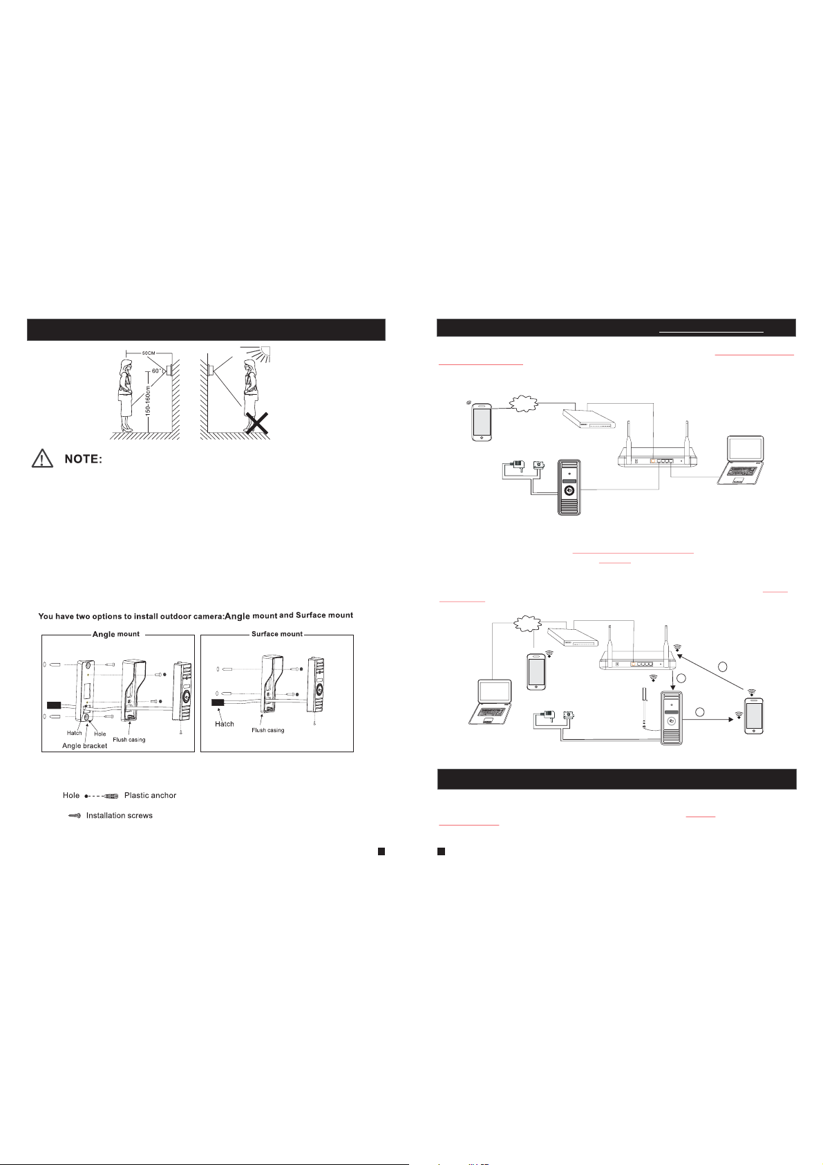
1.5 Installation process of Outdoor Units
* Avoid installation of the device near strong radiation e.g. AC motor and l ift.
* Maint enance sh ould be com plied wit h qualifi ed technician.
* Avoid hard shake, beating and collision, otherwise the internal exac t compone nts maybe
be damaged.
* Do not ex pose the ou tdoor cam era under s trong lig ht or sunsh ine.
* Do not in stall the o utdoor camera in the environment e.g. direct sunlight, contact rain,
High te mperature, high humidity, full of dust and chemistry corrosive.
* Selec t the most su itable po sition wh ere the cam era is located at user’s eye level.
* Switch off power supply before installation.
* Keep mo re than 30c m away from AC p ower supp ly to avoid e xternal interference.
* Keep it away from the water and magnetic field.
Please follow these steps as reference:
1.Select the most suitable position where the outdoor camera is loc ated at use r’s eye le vel, then
drill 2 holes according the weather shield, embed 2 plas tic ancho rs into the h oles.
2.Use a s crewdriver to affix the weather shield with the installation screws.
3.Drag the connection cable through the hatch at the bottom side.
4.Emb ed the outd oor unit in to the weat her shiel d and affix w ith the supplied screws.
7 8
2. Device Connect--Through wired network or wireless network(optional)
A. Us er can co nnect t he outd oor cam era thr ough ne twork c able, o peration steps:
1. Co nnect t he netw ork cab le to the o utdoo r camer a accor ding to s ectio n
the I P o utdo or ca mera
2. Co nnect t he powe r adapt er to the e lectr ical ou tlet of t he outd oor cam era and p ower on .
3. Wa it for a w hil e unti l hearing a b eep, t his tim e the out door ca mera st arts co mplet ely.
Network connection diagram through wired network as Figure 1.
3G/WIFI
IOS/Android
B. The de vice with W IFI funct ion can be al so work wit h WIFI wireless network.
1. If use r connect s a network c able to the o utdoor ca mera, the p aramete rs for WIF I can be set up
via web b rowser, ple ase see sec tion for mor e informa tion,
network connection diagram please refer to on the ab ove.
2.2 Tool Bar
2. If user doesn’t want to connect a wir ed cable to t he device , and user ne eds to prep are a
wirel ess route r and a smart -phone or a p ad with IOS o r Android system. The parameters for WIFI
can be se t up via a smar t-phone or a pad with IOS o r Android sys tem, plea se see sect ion
AP function
Netwo rk connec tion diag ram via wir eless net work as Fig ure 2.
.
Internet
Modem
lock
AC/DC po wer
(not Included)
(not Included)
for mor e informa tion.
Internet
3G/WIFI
IOS/Android
AC/DC power
(not Included)
PC
Router
DOOR
WAN
Figure 1
5.7.3.3 Network--WIFI(optional)
Figure 1
To WAN
Modem
lock
(not Included)
Antenna connector
(optional)
Router
Antenna
(optional)
LAN
WAN
WIFI(LAN)
Figure 2
To WAN
LAN
To LAN
Reset
DOOR
To LAN
Reset
3
WIFI(LAN)
1
AP mode
1.4 w iring d iagra m of
PC
3. Soft
2
WIFI(LAN)
WIFI
(LAN)
IOS/Android
3. Soft AP Function
The outdoor camera with wifi function can be worked in wireless mod e. If user doesn ’t want to conne ct a wired
cable to the device, and user need prepare a wire less router an d a smart-phone or a pad with IOS or And roid
system. The network connection diagram via wireless network please refe r to on section
2.Device Connect.
1) Firs t user must in stall a mobi le operating system specific program onto his mobile or pad. The Android m obile
Figure 2
Page 6

progr am is locate d on the inclu ded CD or down loaded via “Pl ay Store”, and the iPhone or iPad program should
be downloaded via “APP Store”. In “Play Store” or “APP Store”, please search for “MobileEyeDoor+” and install
it onto u ser’s mobile or Pad. Please see the instruction manual for user’s mobile to install the program.
2) Seco nd turn on use r’s phone WL AN function, t hen click the “M obileEyeDoor+” icon to run the program, click
“ ” to select add mode, here must select “ ” to the nex t interface to a dd wireless device.
3) Then long-press the “call” button on the outdoor camera, don’t loosen the button until hearing a beep, t his
means t he device wi ll reboot au tomatica lly and go int o AP mode . Wai t for a moment, when hearing another
beep it m eans the dev ice starts s uccessfu lly and goes i nto AP mode.
4) On “WI FI setting ” interfac e, wait for a mo ment and pho ne with android system can be connected to the device
WIFI su ccessful ly automat ically. For the p hone with IOS sy stem user need t o connect devi ce WIFI functi on
manually. Click “ ” to enter WLAN i nterface o f user’s ph one to see ava ilable net works, and U ID
numbe r of the devic e(the UID is a ttached to t he machine) will be shown on the available networks list.
Select it and connected successfully means the mobile will be connected to the outdoor camera directly(shown
as follows).
5) On this i nterface , Retur n to the “WIFI s etting” in terface an d go to the next s tep. available wireless devices will
be shown on the list. Choose one and click it, if the wireless password o f the wireless r outer is enabl ed, it will
pop-u p a window to enter the password of the wireless router, input the correct pas sword and sett ing ok, the
outdoor device will reboot automatically, it will be connected to the wireles s router aft er startin g when heari ng a
beep again.
6) Clic k “Next Step ” to add outdo or device, i nput the cor rect passwor d of the devic e, default as “8 88888", and th en
save.
7) Retu rn to the WLAN s ettings on t he mobile an d choose the w ireless rout er which the out door device ha s been
connected to. Now the wireless function of the outdoor camera has been activation and works normally(Shown
as follows).
For more details of “MobileEyeDoor+”, please refer to Section .4. Mobi le Phone Sof tware Visit
Note:
1. If the d evice has we nt into AP mode, b ut the wirel ess functi on of the devi ce hasn’t be en activat ion via
“MobileEyeDoor+” on the phone or user doesn’t do any operate about the device , after 10 minut es the
devic e will automatically exit AP mode and returns to the previous connection mode.
2. When t he device we nt into AP mode, l ong-pres s the “Call” b utton again, don’t loosen the button until
heari ng a beep, thi s means the de vice will re boot autom atically a nd will retu rn to the prev ious
connection mode.
In the following diagram, we use a smart-phone with android system to an outdoor camera. The
usage o f an iPhone /iPad with I OS system i s similar.
UID: zz0280a1cb
4. Mobile Phone Software Visit
Thi s IP vide o doo r phon e can t rans mit l ive fe ed to y our mo bil e phon e, an d supp ort P2P f or
mob ile mon itori ng, so th at you ca n have 'o n the go' a ccess t o your surveillance system from
virtually anywhere. To view, you mu st ins tall a mo bile op erati ng syst em spec ific pr ogram i nto
you r mobil e. Curr ently, t her e are a li mit ed num ber o f phon es th at are s upp orte d: Go ogle
And roid an d Ap ple iP hone or i Pad. Th e Andr oid mo bil e prog ram i s loca ted o n the in clu ded CD
or do wnloa ded via “ Play St ore”, a nd an iPh one mob ile pro gram or an iPad program is
dow nload ed via “A PP Stor e”. I n “APP S tore ” or “P lay St ore”, p lease search for “MobileEyeDoor+”.
Ple ase see t he inst ructi on manu al for yo ur mobi le to ins tall th e program.
4.1 Iphone Mobile or Ipad
The iPhone or iPad application, like all iPhone or iPad applicati ons , need s to be d ownl oad ed
dir ectly f rom the Ap p Store . Open APP s tor e, sea rch f or “Mo bil eEye Doo r+”, i t's a f ree ap plication.
The a pplic ation o n the iPa d could b e searc hed for “ iPad On ly” or “i Phone O nly”.
(1) “MobileEyeDoor+” installation
According to the following method, open the App store “ ”, t ouch “ ” a nd se arch f or
“MobileEyeDoor+”. Install it on the mobile phone or the iPad. After installing “MobileEyeDoor+”,
it wi ll appe ar a “ Mobi leEye Door+ ” icon on t he appl icati on software.
(2)
How to use “MobileEyeDoor+”
Click the “MobileEyeDoor+” icon to run the program. Click “ ” t o add a ne w dev ice, f irs t
1>
cli ck “ ” to the i nterf ace t o choo se the ad ding ty pe, the re are th ree met hods
to ad d devic e: “Sca n QR Code ”, “Man ually e nter” a nd “LAN S earch ”.
A. Ad ding b y “Sc an QR Co de”
Cli ck “ ” to the n ext int erfac e, user s can scan QR code attached to the machine
through the mobile phone or the iPad, and the device UID will be sh own.
B. Adding by “Manually enter”
Cli ck “ ” to the n ext int erfac e, user s can add a n ew device by UID type or by IP type.
a.By UI D type
Aft er ente ring th e “UID Typ e” Se ttin gs me nu, th e fol lowi ng fi elds w ill n eed to b e com plet ed:
9
10
Page 7

Name: Set na me for th e outdo or came ra, and s aves se tting s for fut ure usa ge.
UID: The dev ice UID ( UID is at tache d to the ma chine ).
User: The user name set for entering the IP outdoor device system. The de faul t is “A dmin ”.
Password: The password set for entering the outdoor device system. The default is “888888".
Channel Number: Se t the ma x chann els of th e devic e will be c onnec ted.
Click “ ” to sa ve.
b. By I P t ype
Click “IPType” to enter the Settings menu, the following fields wi ll ne ed to be c omp lete d:
Name: Set name for the outdoor device, and saves settings for future usag e.
Address: The public IP address or dynamic domain name of the outdoor device.
Port: The mobile port of the outdoor device for r emot e acces s viewi ng via mo bile ph one or
iPa d, the de fault i s “2051 0”.
User: The user name set for entering the outdoor device system. (Admin by d efau lt)
Password: The password set for entering the outdoor device system. (88888 8 by def aul t)
Channel Number: Selec t the max c hanne ls of the d evice w ill be co nnect ed.
Click “ ” to save.
C. Adding by “LAN Search”
On LA N, turn o n the WIF I of the Wi reles s Route r and the m obile p hone( or the ip ad). Cl ick
“Local Search” and online devices will appear on the “Please choo se th e devi ce” l ist, c lic k
one to add the device, the following fields will need to be completed:
2> After adding the device successfully, the device will appear on the main screen. Click the
dev ice, an d all the c hanne ls of the d evice w ill be sh own on th e scree n. Clic k any cha nnel an d
it will connect immediately. The background of the channel will be hi ghlig hted af ter con necti ng
successfully(shown as follows).
IPDoor 2014-07-25 10:30:32
3> The fu nctions o f the other i cons on the l ive view:
Unloc k.
Snaps hot .
of the ch annel has a n ormal rec ording video symbol “[REC]”. And click it again to stop manual
record.
Click i t to turn the s ound on or di sable.
Click i t to start to t alk, and th e backgro und of the bu tton will be highlighted. Click it again to
stop talking.
Click i t to displa y or hide the b uttons “ ”.
Click i t to enter th e device li st interf ace.
Click i t to enter th e snapsho t file and re cord file .
Click i t to enter th e local set ting inte rface.
Click i t to enter us er guide interface.
4> On the l ive view, use rs can touc h a channel o n the screen and drag it to the other channel
position directly.
5> On the i nterfac e of “Devic e”, user ca n edit the pa rameter s of one dev ice, clic k “ ” to the next
inter face as bel ow. Click “ ” to en ter edit mo de to adjust the parameters. Click “ ” to save.
And cli ck “ ” to remov e the infor mation of t he current device.
: to capt ure a frame o f the video s tream as a st ill photo
Recor d: Click it t o start man ual recor d video on th e curren t channel, and the right top corner
Name: Set n ame for t he outd oor dev ice, an d saves s ettin gs for fu ture us age.
User: The user name set for entering the outdoor device system. (Admin by d efau lt)
Password: The password set for entering the outdoor device system. (88888 8 by def aul t)
Channel Number: Se t the ma x chann els of th e devic e will be c onnec ted.
Click “ ” to sa ve.
[Video Push]: To access the interface about the parameters of one device, there is an o ption
“vide o push” for a larm push f unction . When sele ct “On”, it i ndicat es that the a larm push f unction o f
the cur rent devi ce is enabl ed. To enable ala rm push fun ction, us ers need to m ake sure th e outdoor
11
12
Page 8

device and the mobile phone are both connected to internet.
Note: 1) The alarm push function can be effective, and the device must be add ed by UID ty pe.
2) For the phone with iOS system, please go into “Settings->Notification Center” on you phone,
click on “MobileEyeDoor+” and make sure you have “Badge APP Icon, Sounds, Shown in
Notification Center” enabled. Also make sure you have “Shown on Lock Screen” enabled.
3) When t he option “ video pus h” on the mob ile softw are inte rface is se t to “On”, so meone
press the call button on the outdoor camera, the notification messa ge will be pu shed onto t he
maste r’s phon e or iPad(S hown as bel ow figure ). And users ca n click the a larm list t o access to t he
video live view of the channel directly or access to the video live view to u nlock for t he outdoo r
camera .
[WIFI Setting]: To acces s the inte rface abo ut the para meters of o ne device , there is an o ption
“WIFI Setting” for the outdoor device. Click “WIFI setting”, and av ailable w ireless d evices wi ll be
shown on the list. Choose one and click it, if the wireless password of the wireless router is enabled,
it will pop-up a window to enter the password of the wireless router, input the corre ct passwo rd
and set ting ok, th e outdoor d evice wil l reboot au tomatic ally, it will be connected to the wireless router
after starting when hearing a beep a gain.
Note: I f users wan t to connec t the devic e via wirel ess netwo rk, when th e device r estarts
automatically after completing set of the parameters about WIFI, please unplug the Ethernet cable
connected to the device, otherwise the device will run via wired netw ork.
6>
Click “ ” t o enter the s napshot and record file interface. Click “Photos” or “Records” to swi tch
displ ay interf ace. Click “ ” t o enter edi t
mode, u sers can re move the fi le list tha t they want t o.
Click o ne on the lis t to see the pi cture or th e record.
7> Clic k “ ”to enter th e “System S ettings ” interfa ce as follo ws.
[Video Views]: Se lec t “1" an d onl y one ch ann el vie w will be s hown
on li ve view. S elect “ 4" and qu ad chan nels vi ew will b e shown o n
liv e view.
[Live Preference]: Optio ns incl ude “Re al-ti me” and “ Quali ty”. If
cho ose “Re al-ti me”, th e video e ncode r of the ch annel f or remo te
If choose “Quality”, the video encoder of the channel for remote ac ces s view ing v ia mob ile
phone will consider to the image quality first.
[View Preference]: To set up the image display size when view the channel video. Optio ns
inc lude “” origi nal” an d “tile ”.
access viewing via mobile phone will consider to the frame first;
4.2 Android Mobile
1) Plea se go to the an droid sof tware mar ket “Play S tore” to se arch for “MobileEyeDoor+” and
insta ll it. Or fro m the insta llation C D, copy the s etup soft ware “MobileEyeDoor+.apk” to user's
Andro id phone or t o SD card.
Open your “File Manager” in android phone, and find out the file “MobileEyeDoor+” in your
andro id phone me mory or SD ca rd. Click i t to instal l the softw are. Whe n the appli cation ha s
finished installing, the icon “MobileEyeDoor+ ” will dis play on the s creen of th e phone (shown
as below).
2)Click the “MobileEyeDoor+” icon to run the program, click “ ” to add a new de vice, fir st please
choos e the addin g mode, cli ck “ ” to the int erface to s elect add ing type, t here are
three m ethods to a dd device : “Scan QR co de”, “Man ually en ter” and “L AN Search ”.
13
14
Page 9

A. Ad ding b y “Sc an QR co de”
Click “ ” to th e next in terfa ce, use rs can scan two-dimensional code attached
to th e machi ne thro ugh the m obile p hone, a nd the de vice UI D will be s hown.
B. Adding by “Manually enter”
Click “ ” to th e next in terfa ce, use rs can ad d a new dev ice by UI D type or b y IP type .
a. By I P t ype
Aft er ente ring th e “IP” Se tting s menu, t he foll owing f ields w ill need to be completed:
Name: Set na me for th e outdo or devi ce, and s aves se tting s for fut ure usa ge.
UID: The dev ice UID ( UID is at tache d to the ma chine ).
User: The user name set for entering the outdoor device system. The def ault i s “Admi n”.
Password: The password set for entering the outdoor device system. The defau lt is “88 8888" .
Channel Number: Se t the ma x chann els of th e devic e will be c onnec ted.
Cli ck “ ” to sav e.
C. Adding by “LAN Search”
On LA N, turn o n the WIF I of the Wi reles s Route r and the m obile phone. Click “LAN Search”
and online devices will appear on the “Search number of device” lis t, cl ick on e to ad d the
dev ice, th e follo wing fi elds wi ll need t o be comp leted :
Name: Set n ame for t he outd oor cam era, an d saves s ettin gs for fu ture us age.
Address: The public IP address or dynamic domain name of the outdoor device.
Port: The mobile port of the outdoor device for r emot e acces s viewi ng via mo bile ph one, th e
default is “20510”.
User: The user name set for entering the outdoor device system. (Admin by d efau lt)
Password: The p ass word s et fo r ente rin g the ou tdo or dev ice s yste m. (8 8888 8 by de faul t)
Channel Number: Select the max channels of the device will be connected.
Click “ ” to sa ve.
b. By U ID type
Click “UID” to enter the Settings menu, the following fields will n eed t o be com ple ted:
Name: Set na me for th e outdo or devi ce, and s aves se tting s for fut ure usage.
User: The user name set for entering the outdoor device system. The def ault i s “Admi n”.
Password: The p ass word s et fo r ente rin g the ou tdo or dev ice s yste m. The d efaul t is “888 888".
Channel Number: Se t the ma x chann els of th e devic e will be c onnec ted.
Cli ck “ ” to save.
3) Aft er addi ng the de vice su ccess fully, t he de vice w ill a ppea r on th e main s cre en. Cl ick t he
dev ice, an d all the c hanne ls of the d evice w ill be sh own on th e scree n. Clic k any cha nnel an d
it will connect immediately. The background of the channel will be hi ghlig hted af ter con necti ng
successfully(shown as follows).
IPDoor 2014-04-24 10:20:30
15
16
Page 10

4) The fu nctions o f the other i cons on the l ive view:
Unlock.
Snapshot .
of the channel has a norm al record ing video symbol “[REC]”. And click it again to stop manual
record.
Click i t to turn the s ound on or disable.
Click i t to start to t alk, and th e background of the button will be highlighted. Click it again to
stop talking.
Click i t to displa y or hide the b uttons “ ”.
Click i t to enter th e device li st interf ace.
Click i t to enter th e snapsho t file and re cord file .
Click i t to enter th e local set ting inte rface.
Click i t to enter us er guide in terface .
5) On the l ive view, use rs can touc h a channel o n the scree n and drag i t to the othe r channel
position directly.
6) On the i nterfac e of “Devic es”, user c an edit the p aramete rs of one de vice, cli ck “ ” to the nex t
interface as below. Click “ ” to enter e dit mode to a djust the p aramete rs. Click “ ” t o save.
And cli ck “ ” to remov e the infor mation of t he current device.
: to capt ure a frame o f the video s tream as a st ill photo
Recor d: Click it t o start man ual recor d video on th e current c hannel , and the rig ht top corn er
wirel ess route r after sta rting whe n hearing a b eep agai n.
Note: If users want to connect the device via wireless network, when th e device re starts
autom aticall y after com pleting s et of the par ameters a bout WIFI , please un plug the Et hernet
cable c onnecte d to the devi ce, other wise the de vice will r un via wire d network .
[Alarm Setting]: To acc ess the int erface ab out the par ameters o f one devic e, there is a n option
“Alar m Setting ” for alarm p ush funct ion. When s elect “Op en”, it indicates that the alarm push function
of the cu rrent dev ice is enab led. To enable al arm push fu nction, u sers need t o make sure t he
outdoor camera and the mobile phone are both connected to internet.
Note: 1 ) The alarm p ush funct ion can be ef fective , and the dev ice must be
added b y UID type.
2) When t he option “ Alarm Set ting” on th e mobile so ftware in terface i s
set to “On”, someone press the call button on the outdoor camera, the
notification message will be pushed onto the master’s phone(shown as
the right figure). And users can click the alarm list to access to the video
live vi ew of the cha nnel dire ctly or acc ess to the vi deo live view to unlock
for the o utdoor ca mera.
[WIFI Setting]: To acce ss the inte rface abo ut the para meters of o ne device ,
there i s an option “ WIFI Sett ing” for th e outdoor d evice. Cl ick “WIFI setting”,
and available wireless devices will be shown on the list. Choose one an d
click it, if the wireless password of the wireless router is enabled, it pop-up a
window to enter the password of the wireless router, input the correct
password and setting ok, the outdoor device will reboot automatically, it will be connected to the
17
7) Clic k “ ” to enter th e snapshot and record file interface. Click “snapshot” or “record” to switch
displ ay interf ace. Click “ ” t o enter edi t
mode, u sers can re move the fi le list tha t they want t o.
8) Click “ ”t o enter the “ Setting s” interf ace as foll ows.
Click one on the list to see the picture or the record.
[Video Views]: Op tio ns inc lud e “1" an d “4" . Sele ct “1" an d only on e
cha nnel vi ew will b e shown o n live vi ew. Sele ct “4" an d quad ch annels
vie w will be s hown on l ive vie w.
[Vi deo S tyle ]: Options include “Original” and “Covered”.
5. Web Browser Operation For IP Outdoor Camera
Users c ould set up p aramete rs for the st and-alo ne IP outdo or camera v ia Web brows er.
18
2.1 Mouse Control
Page 11

5.1 Running Environment
Ins tall th e softw are thr ough th e Inter net bro wser of O S to conv enien tly ope rate th e netwo rk
fro m a remot e locat ion. Th is device supports C/S, B/S, and access in LAN and WAN. It also
supports IP and domain name visiting.
IMPORTANT! SOFTWARE RECOMMENDATIONS:
To ensure reliable remote viewing of IPdoor footage, it is highly rec omm ende d tha t user s hav e
either Windows XP, Windows 7 or Win dows 8 installed on their computers, and that they use
either Internet Explorer 6.0, Internet Explorer 7.0, Internet Explorer 8.0, Internet Explorer 9.0
Internet Explorer 10.0, Internet Explorer 11.0, Mozilla Firefox, or Goo gle Ch rome as t heir
Int ernet b rowse r. (In the a ppend ix, the re is an explanation of how to access the IP outdoor
cam era usi ng Fire fox or Go ogle Ch rome. )
Note: Suggested that to run Internet Explorer browser as Administra tor o n oper ati on
system such as Windows 7/Windows 8/Windows 8.1 except Window
XP.
5.2 Network Security Setting
Prior to setting up remote access, set the network security level b y fol lowi ng th e foll owi ng
instructions:
(1) O pen the I ntern et Expl orer br owser a nd clic k the “Tool s” tab lo cated i n the bar a t the top
of the browser; from the drop-down menu, select “Internet Options”.
(2) C lick th e “Secu rity” t ab in the d ialog ue box.
(3) C lick “C ustom l evel” ( at the bo ttom of t he dial ogue bo x) to set t he secu rity le vel.
Set the appropriate settings for the ActiveX controls and plug-ins. F ind th e fol lowi ng co ntro ls
in th e “Secu rity Se tting s” box an d selec t the “En able” o ption f or each o f them. T his i s an
extremely important step.
* Auto matic p rompt ing for Ac tiveX c ontro ls.
* Binary and script behaviors.
* Initialize and script ActiveX controls not marked as safe for scripting.
* Download signed ActiveX controls.
* Download unsigned ActiveX controls.
* Run ActiveX controls and plug-ins.
* Scr ipt Acti veX con trols s afe for s cript ing.
Prompt: Before setting up remote access, turn Disable the firewall a nd any a nti -vir us so ftwa re
currently running on the computer.
5.3 Connection Settings
Rem ote acc ess to th e IP vide o doo r phon e is ca rrie d out o ver th e Internet. In the local area
net work, t he IP add res s of the c lie nt-s ide c ompu ter m ust be i n the s ame ne two rk seg men t that
the I P a ddre ss of t he IP vi deo do or ph one. I n the wid e area ne twork, the only requirement is
tha t the two s ides ca n visit t he publ ic netw ork and c onnec t to the Internet through the IP
add ress or t he dyna mic dom ain nam e. The fo llo wing w ill m ainl y foc us on co nne ctin g and
set ting up t he loca l area ne twork .
Step 1: Right-click on “Network Neighborhood” and click “Propert ies” i n the m enu to o pen t he
“Network Connections” menu. Alternatively, if the operating syste m being u sed doe s not hav e
a “Network Neighborhood” icon, enter the Control Panel found in the “S tart ” men u; the n, cl ick
“Ne twork a nd Inte rnet” , and sel ect “Ne twork a nd Shar ing
Center.” On the “Network and Sharing Center” page, there
sho uld be a “N etwor k” sect ion; in t hat sec tion, t here sh ould be
a “Vi ew St atus ” lin k next t o a lis ting t hat r eads “ Con nect ion :
Loc al Area Co nnect ion.” C lick th e “View S tat us” li nk. A sma ll
“Lo cal Area C onnec tion St atus” w indow w ill app ear; at t he
bot tom of th is scre en, cli ck “Pro perti es”, an d if prom pted to
giv e permi ssion t o conti nue, cl ick “Yes .”
Ste p 2: Doub le-cl ick to op en “Loc al Area Co nnect ion” fr om the
“Network Connections” menu.
Ste p 3: Clic k “Prop ertie s” in the l ower- left co rner of t he wind ow
(see preceding figure).
Step 4: Double-click “Internet protocol (TCP/IP)” from the “This
con necti on uses t he foll owing i tems” l ist in th e cente r of the
win dow (se e prece ding fi gure) .
Ste p 5: The de fau lt IP ad dres s of th e outd oor cam era is 19 2.168 .0.111. S et the c orr espo ndi ng
IP ad dre ss, su bne t mask , and d efau lt ga tewa y on th e PC. If t he su bnet m ask a nd def ault
gat eway on t he comp uter ar e the sam e as thos e of the ou tdoor d evice , then th e IP addr ess i s
most likely in the same network segment. However, the y mus t not be e xac tly th e sam e as the
ones on the outdoor device, as this will cause IP address conflicts. Taking the preceding figure
as an example, the IP address should be: 192.168.0.X, where X cann ot be 244 o r 1 (incl uding
oth er IP add res ses cu rre ntly b ein g used ), an d cann ot ex ceed 2 55, a s the su bnet ma sk is
19
255 .255. 255.0 , and the g atewa y is 192. 168.1 .1.
20
Page 12

5.4 Quick Setting
1)Th rough t he IP out doo r came ra co nnec tio n to net wor k (or PC ), an d then t o the o utdo or de vice
electric start.
Note: if the IP outdoor camera and PC connected directly, PC’s IP ad dres s to use ma nual
distribution methods, and the IP address of the PC network segment and the outdoor
dev ice kee p the sam e netwo rk segm ent.
2)Copy the quick setting guide program “HiCamSearcher_v1.1.exe” fro m the i nsta lla tion C D
to us er’s P C, and r un it o n PC.
2.
3)Pr ess "Ne xt" but ton, po p-up as b elow in terfa ce. Cli ck “Ref resh” b utton a nd onli ne devi ces
on LA N will be s hown on t he list .
Double click one to
access the device.
2.
2.
4)Select a de vice fr om the li st, and p ress “N ext” bu tton to m odify t he sett ing, po p-up as b elow
interface.
21 22
2.4.1 System
5)Op tions “ IP A ddre ss” , “Sub M ask ” and “G ate w ay” ca n be mo difi ed. C lick “ Mod ify” b utt on,
pop -up as be low int erfac e. Inpu t the dev ice’s r igh t acco unt a nd pas swo rd (de fau lt acc oun t
of administrator is “Admin” and default password of administrato r is “88 888 8”).
Page 13

6)Click “OK” to confirm device parameters configuration.
5.5 System Login
1)Op en the we b brows er, ente r the IP ad dress of the device(such as ,
which can be searched by the program “HiCamSearcher_v1.1.exe”.
Not e: If the d evice i s conne cted to t he WAN, t he IP ad dres s shoul d be a publ ic IP address.
The system will automatically enter the GUI as follows.
“http://xxx.xxx.xxx.xxx”)
Cli ck “ Download Player ” and d ownl oad the f ile “IPDoor.zip” to the PC. Open the zip file to
run t he file “ IPDoo r.exe” a nd it wil l insta ll outd oor dev ice’s O CX on t he PC (a cco rdin g to th e
method as following figures).
3)After installing player on the PC, input the authorized user name and p assw ord , the de fau lt
user name is “Admin” and the default password is “888888”. Select l ang uage “ Eng lish ” or
“Chinese”, choose network stream “Main Flow” or “Minor Flow”, and th en cli ck “ ”.
“ ” ind icate s that it w ill ent er into “ Home” i nterf ace aut omati cally w hen the d evice w ill
be co nnect ed to the w eb brow ser aga in on the s ame PC.
2) Clic k “ ”, if users access the device on the PC for the first time, it will pop up a window as
below, click “ok” and install player on the PC according to the fo llowing m ethod.
23
24
Page 14

4)After login, it will enter into “Home” interface of the live view as f oll ows.
IPDoor 20 14-04-25 11:20:08
Not e: Diff ere nt rou ter h as dif fere nt sett ings fo r port fo rward ing; pl ease ki ndly fo llow yo ur
router guide to do the port-forwarding.
Aft er the po rt-fo rward ing is do ne, you c ould vi ew the IP o utd oor ca mer a from WA N now.
5.6 Port Forwarding
If visit IP outdoor camera via Internet Explorer browser from WAN, y ou mu st do po rt fo rwar din g
on th e route r. Port Fo rward ing is us ed to tra nsfer i nform ation from your router directly to your
computer or outdoor device through Ports. What is a Por t? Po rts ar e ope ning s thr ough your
computer that allow data in you computer/outdoor device. The World Wide Web for example
use s Port 80 . An ytim e you go to a w ebsite, that goes over that specific port. The reason we
nee d to forw ard cer tain po rts for y our out door ca mera is s o that yo u can vie w your ca meras
ove r the Web (in tern et) .Take Ne tge ar rou ter f or exa mpl e.
A few things that you need to find out about your Internet Connection:
* Do yo u have a St atic IP o r Dyn amic I P? To find t his o ut, co ntact y our Int ernet S ervic e Provi der
and they should be able to tell you.
* If yo u have a Dy namic I P o r PPPo E ADSL , you wi ll ne ed to se t up an Ac coun t on DD NS
(www.dyndns.org or www.3322.org). That way when your IP changes, you ca n con nect t o the
same Hostname (ex: my.dyndns.org) everytime you connect. In other wo rds , it mak es your
Dynamic IP a static host address. This is very important if you wa nt to co nnect t o your ou tdoor
device remotely.
* Find out what equipment you are using from the Internet Service Provider. If i t is a mod em,
then you should be fine just configuring your router that's conne cte d to it. M ake s ure to g et th e
use rname a nd pass words f or any ro uter yo u may hav e. If you c an not lo g in to the r outer, y ou
wil l not be ab le to com plete t his set up. You may h ave to co ntact y our Int ernet S ervic e Provi der
for this information.
Take Ne tgear r outer f or exam ple.
Operation Steps:
1) Aft er logi n the int erfac e of the ro uter, ch oose “Port Forwarding”;
2) Choose “Add custom Service”;
3) In put IP ou tdo or cam era p orts , inc ludi ng ht tp por t 80 an d mobile port 20510;
4)Input IP address of the outdoor device, click “Apply”(the HT TP port , the mo bile po rt and IP
address should be the same as the following figure which set by yo ur own) .
5.7 Function Settings
Options in the main interface include “Home”, “Media”, “Parameters” and “System”. Click any
opt ion to ac cess it .
5.7.1 Home
Cli ck “Hom e” to ent er the wi ndow fo r live vi deo as fo llows , it incl udes vi deo win dow, con trol
but tons an d Image S ettin gs.
Video window: Double click the real-time video then it will display video full-screen. Double
click it again then it will recovery default window.
Control buttons:
Record: Click “ R ecord” bu tton, whi ch could re cord the vi deo with au dio and sto re it at the
present path. When recording, the button “ ’’ wi ll change t o ‘‘ ’’. Click t he button “ ” again,
and the n the recor d stops.
Capture: Click t he captur e button, w hich coul d take phot os for the cu rrent vid eo and sto re the
image a t the prese nt path.
Image Settings:
: Adjust hu e of image. Valu es can be se t from 0~10 0.By defa ult, the va lue is
set at 50 .
: Adjust br ightnes s of image. Val ues can be se t from 0~10 0.By defa ult, the va lue
is set at 5 0.
: Adjust co ntrast of i mage. Values c an be set fr om 0~100. By defaul t, the valu e is
set at 50 .
: Adjust sa turatio n of image. Valu es can be se t from 0~10 0.By defa ult, the va lue
is set at 5 0.
Powerfreq (Power Line Frequency): Options include 50HZ and 60HZ. If the monitoring site adopting
light ing elimi nation, u ser shoul d set a corre spondi ng freque ncy. If the two frequencies are different,
the image will flick. There are two frequencies on the world, one is 50HZ, and the other is 60HZ. In
China , adopt 50H Z.
Click “ ” t o refresh t he settin gs of the Ima ge, and cli ck “ ” to resto re the para meters of
25
the image to the default settings.
26
Page 15

Stream: Set up ne twork str eam, incl uding mai n flow and mi nor flow.
Image: Set up th e size of vie w image. Op tions inc lude Fit si ze and Src si ze.
5.7.2 Media
Click “Media” to enter the media parameter setting menu. This int erfa ce in clud es sett ings fo r
Vid eo an d OSD.
5.7.2.1 Media--Video
Click “Media—Video” to access the interface as follows. And user can set up parameters of main
strea m, sub stre am and mobi le stream .
A. Video—Main Stream and Sub Stream
1)Resolution: For the resolution of main stream, there is only 720P(1280*720). And for the
resolution of sub stream, there is only VGA (640*360). The bigger th e reso lut ion is , the cle arer
the i mage wi ll be. On t he othe r hand th e bit rat e is bigg er and ta kes mor e bandw idth.
2)Bit R ate: Us er can ch oose a ce rtain b it rate , gener ally sp eakin g, the bi gger th e bit rat e is,
the clearer the image will be. Please choose the suitable bit rate according to your bandwidth.
If you select a big b it rat e, whil e the ban dwidt h is wors e, it wil l cause t he vide o strea m can't b e
tra nsfer red smo othly, t he vi deo qu ali ty wil l be no t perf ect t oo. Th e defa ult bit r ate val ue of mai n
stream is 2048kbps. And the default bit rate value of sub stream is 1024kbps.
3)Max imum Fr ame: Us er can ch oose a ce rtain f rame ra te, whe n the ban dwidt h is limi ted,
suggest reducing the value. Generally, the video is fluency if the v alue i s mor e 15 fra mes .
Def ault va lue is 30 f rames f or NTSC n orm and i s 25 fram es for PAL norm.
4)Bit Rate Type: There are three modes for bit rate control, CBR, VBR a nd Fix Qp. If us er
choose CBR mode, the video encoder will encode according to the bit r ate you hav e sel ecte d.
If user choose VBR mode, the video encoder will consider to the im age qua lity an d encod e
acc ordin g to the bi t rated h ave bee n selec ted, bu t not str ictly according to this bit rate. Suggest
VBR mode.
5)Audio: Options include “On” and “Off”.----(Optional)
B. Video—Mobile Stream
1)Resolution:The res oluti on of mob ile str eam is QV GA (320* 180).
2)Quality: The image quality of the outdoor camera for remote acce ss vie win g via mo bile ph one.
And th ere are f ive opt ions: “ Very Hig h”, “Hi gh”, “N ormal ”, “Low ” and “Ver y Low”. T he be tter t he
ima ge qual ity is, t he bigg er the bi t rate an d the fra me rate o f the out door ca mera ar e. Plea se
choose the suitable quality according to your bandwidth.
C. Video Norm
Fro m this fi eld, se lect th e syste m outpu t type fo r outdo or came ra, i.e . PAL o r NTSC .
Note: The device will restart automatically if the outdoor camera out put typ e is chan ged.
5.7.2.2 Media--OSD
Cli ck “Med ia—OS D” to acc ess the i nterf ace as fo llows . OSD opt ions in clude “ Time St amp” ,
“De vice Na me” and “ Name” .
1)Time S tam p: Fro m thi s fiel d, us ers ca n dec ide ti me st amp wi ll be s hown o n the h ome pa ge
for l ive vie wing as t he OSD (O n-Scr een Dis play) s tring w ether o r not.
2)Device Name: User can add the equipment's name on the home page for live viewing
through this setting.
3)Name: User s can mod ify the n ame of th e outdo or devi ce. Not e that th e name of t he devi ce
mus t not exc eed twe lve ara bic num bers, l etter s or twel ve Chin ese characters.
5.7.3 Parameters
Cli ck “Med ia” to en ter the p arame ters se tting m enu. Th is in terf ace includes settings for
Network (Basic Settings, DDNS, and Wifi-optional) and Event (Record).
27
28
Page 16

5.7.3.1 Network--Basic Settings
Click “Parameters—Network—Basic Settings” to enter the LAN Setting s int erfa ce. D efau lt IP
type is “dynamic IP Address”. The user can set up device network pa rame ters th rough t he
operation “Quick Setting Guide”, user can change it according to your network environment.
A. LAN Settings
[IP Type]: There are two options: “Fixed IP Address” and “dynamic IP Address”.
After selecting an Internet connection setting - su ch as fi xed I P address (static) or dynamic IP
address (DHCP) – and all ocati ng a port , users c an acce ss the IP o utd oor ca mer a remo tel y via
the Internet.
1)If f ixed IP a ddr ess ha s bee n sele cte d, it is n ece ssar y to se t up an IP a ddre ss, a sub net mas k
and a g ateway.
[IP Address]: Ente r the IP ad dre ss in th is fi eld.
[Subnet Mask]: Input numbers for the subnet mask.
[Gateway]: Enter numbers for the default gateway.
[DNS Type]: Options include “Manual DNS” and “From DHCP Server”. If users selec t “Manu al
DNS ”, they h ave to in put num bers fo r prima ry DNS an d secon d DNS man ually.
2)If DHCP is selected, the server will allocate an outdoor camera IP address automatically.
NOT E: Save t he IP add res s when s ele ctin g DHC P and th e outd oor camera will automatically
connect with the server. It w ill a llocate an IP address when the connection is stable, and this
address will be displayed on the interface.
B. HT TP
[HTTP Port] : The IP ad dress i denti ty one ou tdoor d evice i n the net work, y ou can ru n sever al
pro grams o n this eq uipme nt, and e very pr ogram w ill tra nsfer t he data t hroug h some po rt, in fa ct
dat a is tran sferr ed from o ne port t o anoth er. The po rt se ttin g of th is pag e is as king u ser c hoos e
which port to transfer the data for the web server. Doi ng por t map ping , nee d to mai nta in
con siste nt with t he port ( equip ment fa ctory d efaul t port is 8 0).Se ts up a Web browser port via
HTT P. The d efa ult po rt nu mber i s “80 ”.
[Mobile port]: Mobile monitoring port. And default value is 20510.
C. Network Test
[Wa n Test] : In thi s field , users c an fill i n the IP ad dre ss or DD NS ad dres s whi ch the y set u p,
and c lick “ ” to t est the n etwor k traff ic is n orma l or not. If all the network parameters are
set c orrec tly, cli ck “ ”
be shown.
and “Tes t Suc cess !” wi ll be sh own . Othe rwi se “Test F ail ure! ” will
5.7.3.2 Network--DDNS
Click “Parameters-Network-DDNS”to enter the DDNS setting interface . DDNS setu p as follow s.
User ca n use third p art DDNS, f irst user m ust have a do main name; www.dyndns.org or
www.3322.org is recommended. Please remember the username, password and domain name.
Then en able DDNS , for examp le, selec t the DDNS Pr ovider a s “3322.org”. If your domain name
is “test.f3322.org”, please enter “test.f3322.org” in the option “Your Doma in”, the “U sername ” and
“Pass word” is th e usernam e and passw ord that ap plied in t he www.3322 .org. Cli ck “ ” to
save. T hen you can a ccess the d evice by do main name .
5.7.3.3 Network--Wifi(Optional, please take actual machine as quasi)
For the outdoor device wi th WIFI f unc tion , users c an visi t the device remotely by the following
met hods: t hroug h netwo rk cabl e conne ction o r throu gh wire less co nnect ion. If t hroug h wirel ess
con necti on, ple ase use t he netw ork cab le to con nect th e devic e into LA N befor e doing s ettin gs
of wi reles s conne ction . T hen cl ick “ Para met ers— Net work —Wi Fi” to e nte r the Wi fi Se ttin g
int erfac e, and ac cordi ng to the b elow 1- 6 steps t o do the se ttings.
1) Op en wire less, “ ” i ndicates WIFI status to be enabled.
2) Cl ick the “ ” b utton t o searc h the current wireless routers, and all the wireless routers
wil l appea r on the Cu rrent H ot Poin t list.
3) Ch oose on e effec tiv e rout er, cl ick it t o cho ose ro ute r SSID .
4) In put cor rect pa sswor d of the wi reles s route r in wire less se curity mode.
5) Cl ick “ ” to ch eck the w irele ss netw ork is co nnected successfully or not.
6)W hen the w irele ss is con necte d succe ssful ly, clic k “ ” to sa ve the s ett ings , the d evic e
wil l be rebo ot auto matic ally, ta ke aw ay the E the rnet c abl e, the n the w irel ess n etwo rk wi ll wor k
perfectly.
Note: 1. When adjust WIFI status, the device will be reboot after sav ing th e setti ng.
2. Wh en enab le WIFI s tatus , the dev ice wil l be rebo ot auto matic ally if plug or unplug the
network cable connected to the outdoor device.
3. Th rough W ifi c onne cti on, th e “Ne twor k Type” o n the Net work Basic Setting suggested
to be set as “DHCP”. When configure the parameters about WIFI, user can view the outdoor
29
device can be allocated IP address whether or not through the search tool “HiCamSearcher”.
30
Page 17

If no t, user m ust set u p param eters a bout Wi fi ag ain.
4. When the equipment connected to the Internet, and also enable th e WIF I, whe n
activated, the equipment will be the first to choose Ethernet cable connection mode, if
can't connect, then choose WIFI connection. WIFI connection of the p orts t o use a re
con siste nt with c able co nnect ion of th e ports t o use.
5.7.4 System
Click “System” to enter the parameters setting menu. This interface i nclud es sett ing s for Us er,
Time setting, Initialize, Device info, Storage Device and System Lo go.
5.7.4.1 System-User
Cli ck “Sys tem—u ser” to a ccess u ser set ting me nu, the d efaul t usern ame and p asswo rd of
adm inist rator i s “Admi n” and “8 88888 ”.
5.7.4.2 System-Time Setting
Click “System—Time setting” to access time setting menu. There are fo ur typ es of t ime mo de:
keep current, manual, Sync with computer time and Sync with NTP.
1) “Keep Current” mea ns the sy stem ti me won' t be chan ged.
2) “Manual” m eans ad just ti me manu ally. Us ers n eed to e nte r date & t ime a nd tim e zon e
31
manually.
32
Page 18

3) “Sync with computer time” mea ns thr ough th is appl y to sync I P ou tdoor c amera s ystem
tim e to loca l PC time .
4) “S ync wit h NTP” wi ll choo se a same t ime zon e with th e NTP ser ver a utom ati call y. Serv er
nam e is the NT P s erve r hos t, and t he in terv al of r efre sh ti me includes 1 ho ur, 2 ho urs, 1 2 hou rs
and 24hous. Save all parameters, then it will update as a net work c loc k.
5) “Delay push(s)”: From th is field, u ser can adj ust delay d uration t ime of alar m push for visitor
calling, and values can be set from 0 to 60 s. For exam ple, to sel ect 5s, if vi sitor pre sses the call
butto n on the outd oor camer a, the mess age will be p ushed on to the mast er’s phon e after 5
seconds.
5.7.4.3 System-Initialize
Click “System—Initialize” to access initialize setting menu. This in terf ace inc ludes s ettin gs for
Reboot, Factory Default and Upgrade.
3) Up grade : Click “ ” t o selec t the fir mware f ile for u pgrading, for example, the
firmware file such as “hi3518-96223-V1003-20140421.ov” is on the des kto p. Fir st ch oose t he
fir mware f ile, cl ick “ ”, an d it will b e shown a s “ ”,the n
cli ck “ ” to upg rade th e equip ment wh ether o r not. Aft er the up gradi ng, the e quipm ent
wil l resta rt.
Not e: Duri ng upgr ading , pleas e don’t p ower of f the o utdo or de vice.
5.7.4.4 System-Device Info
Click “System—Device Info” to enter the “Device Information” menu as follows. The information
inc luded a ccess ible th rough t his int erfac e inclu des: De vice In fo (Dev ice Nam e, Devi ce ID,
Sof tware Ve rsion , Relea se date a nd Star t Ti me), N etwor k Info (C onnec tion, M ac, IP, Sub net
Mas k, Gate way, Pri mar y DNS an d Sec ond DN S).
1) Reboot: Click “ ” , it will p op-up a m essag e windo w “the device will be rebooted. Are
you sure?”, and cl ick “OK ” to rest art the e quipm ent.
2) Factory Default: Cli ck “ ” , it wi ll pop- up a mess age win dow “Se t up data w ill be
initialized. Are you sure?” Cl ick “O K” to r esto re al l the pa ram eter s to th e defa ult s etti ngs
exc ept IP ad dre ss.
5.7.4.5 System-Storage Device
Cli ck “Sys tem—S torag e Devic e” to ent er the in terfa ce of SD ca rd info rmati on as fol lows.
The option “status” for the models without SD card will show “no ready”.
33
34
Page 19

5.7.4.6 System-System Log
Click “System—System Log” to enter the “system log” menu as follows.
At th e top of th e “Log Se arch” p age are t he foll owing f ilter s to faci litat e locat ing the d esire d file( s):
[Time] : Set the s tarti ng time a nd the en ding ti me of the l og bein g searched for.
[Ty pe]: Choose from the following options: “All”, “Alarm” and “Operation”.
Click the “ ” butto n after s ettin g the log t ime and t ype, an d the sys tem wil l displ ay the
selected log in the list. Click “ ”, “ ” , “ ”, “ ” to navigate pages, and
cli ck “ ” to delete all the log lists.
5.7.5 Logout
Click “Logout” to log out of the system.
Appendix 1. Accessing the IP outdoor camera via Mozilla Firefox
1.Firs t, instal l Firefox o n Windows (This doc ument wil l use Fire fox 28.0 as an example).
2. After installing Firefox, please search for the “IE Tab” add-on fo r Firefox , which can b e
downloaded from Firefox browser.
3. Open Firefox, click “Tools-->Add-ons” to enter into the interface of “ Get Add-ons ”, and sear ch
for “IE Tab”, a ll the IE tab s will be sho wn on the lis t for “Available Add-ons”. Choose one and install
it, thi s documen t will use IE Tab 2(F F 3.6+)5. 12.12.1 f or example.
4. After in stallin g the IE Tab, user ne ed restar t Firefox b rowser.
5. Open F irefox an d enter the o utdoor de vice IP add ress in the a ddress fi eld. Righ t-click a t blank,
select “View Page in IE tab”. The outdoor device can now be connected successfully.
Appendix 2. Accessing the IP outdoor camera via google Chrome
1.First, installing Google Chrome Browser on Windows(this manual will use Chrome version
34.0. 1847.116 m as a n example ).
2. After in stallin g Google Ch rome, sea rch for the “ IE Tab ” add-on fo r Chrome, w hich can be
downloaded from the Chrome Web Store.
3. Open ing Chrom e, click “ Cu stomize a nd contro l Google Ch rome->Tools->Extensions->
browser the gallery” to enter the “Chrome Web Store” interface to sear ch for “IE Tab”, an d results
for IE ta b in Extens ions will a ppear on th e right sid e. Choos e one to inst all it and it ’s free for
installation(Shown as below).
35
36
Page 20

4. During installation, the following figure will appear, click “Ad d” to confi rm to insta ll “IE Tab”
add-on.
5. After complete installation, the icon “ ” wil l appear on t he right to p of the brow ser inter face
(Show n on the red fr ame as belo w), and it me ans that IE Tab has been added to Chrome browser.
6. Clic k the icon “ ” on t he right to p of the addr ess field t o display t he Chrome w eb page in a n
IE-ba sed page, a nd fill in th e IP addres s of the outd oor devic e on the IE-based address bar, then
click t he icon “ ” to ac cess the re mote devi ce, fill in t he correct user name and password to log in.
Defau lt user nam e and passw ord are “Ad min” and “8 88888" .(shown on the red frames as below)
Appendix 3 How to ensure reliable remote viewing of the IP
outdoor camera through IE browser on Win 7/Win 8 64bit OS
1. Run 32bit IE on Windows OS (64bit)
Note: On a 64- bit ver sion of a W indows operating system, there are two versions of the
Internet Explorer files:
37
* The 64-bit version is “C:\Program Files\ Internet Explorer \iexplore.exe”.
* The 32-bit version is “C:\Program Files(x86) \ In tern et Expl orer \i explore.exe”.
* Ple ase run t he 32-b it vers ion “C: \Program Files(x86) \Internet Explorer \iexplore.exe”.
2. Run Internet Explorer as the Administrator
1) Open folder path “C:\Program Files(x86) \Internet Explorer”.
2) Ri ght cli ck the In terne t Explo rer ico n and cho ose "Run as Administrator".
3) Click "Continue" in the User Account Control window to grant admi nis trat or ac cess t o
Internet Explorer.
3. Download ActiveX control after type in IP address & Po rt
1) Op en an Int ernet E xplor er brow ser win dow to ma ke chan ges to yo ur curr ent Acti veX con trols .
Click the “Tools” link located at the top of the menu bar. A drop do wn wind ow will a ppear w ith
sev eral mo re opti ons to ch oose fr om. Eac h optio n will le t you cha nge som e of the de fault
settings already programmed into Internet Explorer.
2) Click the “Internet Options” link located at the end of the list. When the pop-up window
app ears, s elect t he “Sec urity ” tab to ac cess th e Ac tive X contr ols. There are several zones with
mul tiple s ecuri ty sett ings. E ach zon e has pre set set tings b uilt in to it. You ca n chang e the
set tings t o fit you r curre nt need s. If for s ome rea son you 're not s atisf ied wit h these c hange s,
cli ck the “R eset All Z ones to D efaul t Level ” to chan ge them b ack. To all ow Act iveX c ont rols t o
run , click t he “Int ernet ” zone. T he ic on tha t ide ntif ies t his zo ne lo oks li ke Ea rth.
38
Page 21

3) Change the security level for the “Internet” zone from the defau lt “M ediu m-h igh” z one t o
“Medium". Slide the bar up and down between the different security zones. The “Medium”
Int ernet z one wil l allow a l ower se curity environment for your web browsing. To go even
further with enabling the ActiveX controls, click the “Custom Level ” butt on. U nder t he
“Settings” menu, look for the “ActiveX Controls and Plug-ins” options. Normally, these
settings are disabled to prevent a security risk to your computer system.
4) Allow the ActiveX controls to automatically run by changing the se tti ngs fr om “D isab le” t o
“Enable”. This can be done by clicking the “Enable” button next to “Allow Previously Unused
Act iveX Co ntrol s to Run wi thout P rompt ”. After m aking t hese ch anges t o your In terne t
Explorer browser, you won 't be con stant ly prom pted to e nable t he Activ eX cont rols. They'll
aut omati cally b e allow ed with out pro mptin g you to ma nuall y do so. Th e cha nges m ade i n
the se sett ings wi ll not ta ke full e ffect u nti l you cl ose a nd restart the Internet Explorer browser
window.
4. Fix site display problems with Compatibility View
Som etime s a websi te you' re visi ting do esn't l ook lik e you exp ect it to . Image s might n ot show
up, m enus mi ght be ou t of plac e, and te xt boxe s could b e jumbl ed toge ther. Th is ca n be cau sed
by a co mpatibility problem between Internet Explorer and the site you're on . When a s ite i s
incompatible with Internet Explorer, yo u'll se e the Com patib ility V iew bu tton in t he Addr ess ba r.
You can only turn on Compatibility View in Internet Explorer for the desktop.
A. To tu rn on C ompa tib ilit y View
1) Se e if the Co mpati bilit y View bu tto n appe ars i n the Add res s bar. (I f you d on't s ee th e
but ton, th ere's n o need to t urn on Co mpati bilit y View.)
2) Tap or c lic k the Co mpa tibi lit y View b utto n to disp lay the s ite in Co mpati bilit y View.
Onc e you tur n on Comp atibi lity Vi ew, In ternet Explorer will automatically show that site in
Compatibility View each time you visit. You can turn it off by ta pping o r click ing the b utton
again. Or, you can c lear th e entir e list of s ites us ing Compatibility View by deleting your
browsing history.
B. To cl ear t he lis t of Co mpat ibi lity V iew si tes
Not all website display problems are caused by browser incompatibility. Interrupted Internet
connections, heavy traffic, or problems with the website can also aff ect ho w a page is d ispla yed.
If yo u're ha ving ot her pro blems o n a site, s uch as pl aying v ideos , read Vi deo w on't p lay i n
Internet Explorer.
The Compatibility List is frequently updated, and Internet Explorer automatically downloads
these update. This list includes sites that might've been designed fo r older o r other b rowse rs,
sit es that u se Adobe F lash Pl ayer, an d other s ettin gs that h elp giv e you a bet ter bro wsing
experience. If you don't want these updates, you can turn off Compa tibi lit y List U pdate s at
any time.
C. To turn off Compatibility List Updates
1) Op en Inte rnet Ex plore r in the de sktop .
2) Pr ess the Al t key to di splay t he Menu b ar (or pr ess and h old the Ad dress b ar and th en sele ct
Menu bar).
3)Tap or click Tools, and then tap or click Compatibility View settings.
4) Clear the Download updated compatibility lists from Microsoft c heck b ox, a nd the n tap o r
click Close.
D. To change Compatibility View settings
1) Op en Inte rnet Ex plore r in the de sktop .
2) Pr ess the Al t key to di splay t he Menu b ar (or pr ess and h old the Address bar and then select
Menu bar).
3) Tap or click Tools, and then tap or click Compatibility View settings.
39
* If ther e is any doubt o r disputab le regardi ng informa tion in this man ual, you can cal l our company fo r
clarification.
* There maybe some differences between the descriptions provided here and th e actual devic es, as our
produ cts are cons tantly dev eloping an d upgradin g. We apologize i f this manual do es not contain a ll of the
lates t updates. Thanks.
40
Statement
Page 22

FCC Radiation Exposure Statement:
This equipment complies with FCC radiation exposure limits set forth for an uncontrolled environment. This
equipment should be installed and operated with minimum distance 10cm between the radiator & your body.
FCC Warning
This device complies with Part 15 of the FCC Rules. Operation is subject to the following two conditions:
(1) This device may not cause harmful interference, and (2) this device must accept any interference received,
including interference that may cause undesired operation.
NOTE 1: This equipment has been tested and found to comply with the limits for a Class B digital device,
pursuant to part 15 of the FCC Rules. These limits are designed to provide reasonable protection against harmful
interference in a residential installation. This equipment generates, uses and can radiate radio frequency energy
and, if not installed and used in accordance with the instructions, may cause harmful interference to radio
communications. However, there is no guarantee that interference will not occur in a particular installation. If this
equipment does cause harmful interference to radio or television reception, which can be determined by turning
the equipment off and on, the user is encouraged to try to correct the interference by one or more of the following
measures:
- Reorient or relocate the receiving antenna.
- Increase the separation between the equipment and receiver.
-Connect the equipment into an outlet on a circuit different from that to which the receiver is connected.
-Consult the dealer or an experienced radio/TV technician for help.
NOTE 2: Any changes or modifications to this unit not expressly approved by the party responsible for
compliance could void the user's authority to operate the equipment.
 Loading...