

Page 1
Statement
* I f th er e is any do ub t or disp ut ab le rega rd in g in fo rmati on i n t his
manua l, yo u c an c al l o ur compa ny fo r c larif ic at io n.
* In a ll c ases, f or m or e d et ai ls , pleas e re fe r to th e el ectro ni c us er ’s
ma nu al o n the i nc lu de d. Th an ks .
.... .. .. .. .. ..... ..
MC-1067(A-2)
Page 2
1 Safe ty In str uct ion s
※ Rea d thes e in struc tions and keep t hem in a sa fe p lace f or f uture ref erenc e.
※ Pl ea se refer al l w or k re la te d t o the i ns ta ll at io n o f th is pr od uc t to qu al if ie d
ser vice p ers onnel or s ystem techn ici an.
※ Do n ot ope rat e the a pplia nce beyon d it s spec ifi ed tem per ature , humidit y or
pow er sou rce ratin gs.
※ Sec urely ins tall t he dev ice s on ve rti cal su rfa ces(s oli d wall s/doors) not pr one
to v ibrat ion or imp act .
※ Ins tall t he d evice s away fro m heat sou rces s uch as rad iat ors, h eat regis ters
and stove s.
※ In st al la ti on o f t he te rminal n ea r c on su me r el ec tr on ic s d ev ic es, e. g. st er eo
receiver/ ampl ifie rs and televisions, i s perm itte d as lo ng as the air surroundi ng
the termi nal does n ot e xceed the above menti one d temp era ture r ang e.
※ Han dle th e ap plian ce wit h ca re. Do not strik e or shake , as this m ay d amage
the devic e.
※ The doorb ell /came ra uni ts s hould be f itted wit h an ap pro ved we ather shi eld
if t he cho sen posit ion is in dir ect su nli ght, o r in conta ct w ith ra in, snow o r
irr igati on s prink ler syste ms.
※ Do n ot use str ong or abras ive deter gen ts whe n cl eanin g th e appl iance bod y.
Whe n the d irt is har d to remov e, u se a mi ld det erg ent an d wi pe gen tly .
※ Do not overl oad outlets and exten sion cords as thi s may r esult in a ri sk of fire
or e lectr ic s hock. Dis tribu ting, cop ying, dis assem bli ng, re ver se com pil ing,
rev erse e ngi neeri ng, and al so exp ort ing in vio latio n of expor t la ws of t he
sof tware pro vided wit h this product, is exp res sly pr ohi bited .
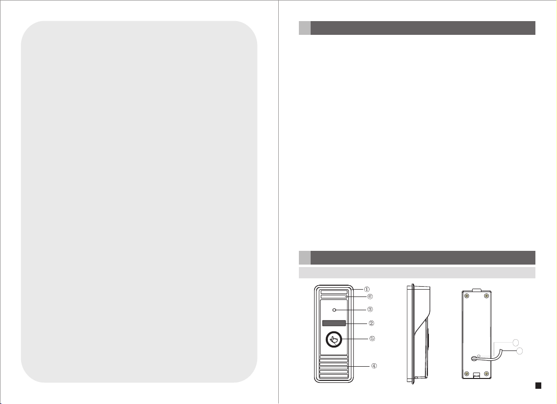
Description Of IP Outdoor camera
2
2.1 Feature (Please take actual model as quasi)
8
7
1
Page 3

No. Name Des criptions
1 Weath er shi eld Affi x and pr otect outdoor c amera from rain o r snow.
2 IR LEDs Provides i llumination w ith IR LEDs for bet ter vi sibilit y.
3 Camera Capture i mage to transmi t to display
4 Speaker Sound fr om smart-phon e
5 Call butto n Visitor call for i ntercommuni cation
6 Micropho ne Trans mit voice to smar t-phone
For the m odels w ith wir ed function, c onnect the doo rbell to exter nal
System por t
7
Volume regulator
8
2.2 Specifications
switc hing po wer supply(D C 12V), ethern et cable and doo r lock.
For the m odels w ith wir eless functi on, connect th e doorbell to ex ternal
switc hing po wer supply(D C 12V), door loc k and indoor ant enna or
outdo or ante nna, an d antenna can be o ptional.
To be used to adjust t he spe aker volu me.
2.3 Fitting of the IP Outdoor Camera
Outdoor ca mera
Plastic an chor
Installa tion s crews
Affix atio n screws
Weath er shi eld
Angle brac ket
Installa tion C D (with ful l manu al and
android mo bile p hone soft ware )
This quick g uide
External S witc hing Powe r Adapte r
Antenna
(optiona l)
Indoor ant enna (option al)
outdoor an tenn a(optio nal)
1pcs
2pcs
2pcs
3pcs
1pcs
1pcs
1pcs
1pcs
1pcs
1pcs (6dBi o r 3dBi )
1pcs (10dB i)
2.4 Wiring Diagram of the IP Outdoor Camera
Antenna(optio nal)
Outdo or
Indoo r anten na
anten na
(opti onal)
(optio nal)
or
or
Camera
View an gle
Definito n(Ho r.)
LEDs for nig ht
Power cons umpt ion
Power supp lier
Network In terf ace
Operatio n temp .
Installa tion
1/4 CMOS
o
60
1.0M
IR LEDs(60 )
o
300mA max.
External s witc hing powe r supp ly DC12V.
10/100M
-40~+50℃
Surface/ flus h mount
Antenna(optional)
Anten na conn ector
(opti onal)
b
Note: G N--G reen, W H--W hite, O G--O range , RD-- Red, B K--Bl ack, B N--Br own.
The terminal is defined functiona lity as bel ow:
1.GN&WH: To netwo rk wire GN& WH 2.G N: To network wire G N
3.OG&WH: To netwo rk wire OG& WH 4.O G: To network wire O G
5.RD: DC 12V 6.BK: G ND 7/8 .BN: To door lock.
To Intern et
Netwo rk Cab le
1.GN&W H
2.GN
3.OG&W H
4.OG
5.RD:D C 12V
6.BK:G ND
7.BN
8.BN
OG&WH
GN&WH
+
OG
-
Extern al switching p ower supply
GN
DC 12V
32
Page 4

In the stand ard de livery th e syst em support lock s with Normally O pen( N.O.) doo r
unlockin g meth od. It mean s that i n the normal stat e the dry contact (mar ked as )
is opened, s o the lo ck is kept un der co nstant closed s tate. If the unlo ckin g button
is pressed a nd the d ry contac t is cha nged to closed, t hen the lock is rel ease d.
If the speaker volume is too low, how t o increase it?
At the backs ide of o utdoor unit, yo u can find out a regu lator (Marked a s )
which is used to adjust the speaker volume, turn the regulator with the screwdriver
to decreas e/in crease th e spea ker volume.
b
2.5 Installation process of Outdoor Units
Please follow these step s as refere nce:
1.Select t he mos t suitable posi tion where the ou tdoor camera is l ocat ed at user ’s
eye level, t hen dr ill 2 holes a ccor ding the weathe r shield, embed 2 p lastic
anchors in to the h oles.
2.Use a scre wdri ver to affix t he weather shie ld with the insta llation screw s.
3.Drag the c onne ction cab le thr ough the hatch at t he bottom side.
4.Embed the outdoor unit into the weather shield and affix with the supplied screws.
* Avoi d inst allat io n of the devic e ne ar s tr ong radia tion e .g. AC mo tor and li ft.
* Ma inten ance s hou ld be comp li ed w ith quali fi ed t echni cian.
* Avoid hard shake, beating and collision, otherwise the internal exact components
ma ybe be d am aged.
* Do not exp os e th e ou td oor camer a un de r st rong l igh t or sunsh in e.
* Do not ins ta ll t he o ut doo r came ra i n the envi ro nme nt e.g . di re ct s unlig ht,
co ntact rai n, H ig h te mpera tu re, high humi di ty, fu ll o f dust and chemi stry
co rrosi ve.
* Select the most suitable position where the camera is located at user’s eye level.
* Sw itch off powe r su pply b efore ins talla ti on.
* Keep more than 30cm away from AC power supply to avoid external interference.
* Ke ep it a way fr om t he wat er and ma gne ti c fi el d.
4 5
3 Device Con ne ct--Throu gh wired network or wireles s network(optio nal)
A. Use r ca n co nn ec t the out do or c am er a throu gh n et wo rk c abl e,
oper at io n st ep s:
1. Con ne ct t he n et work ca bl e to t he o ut doo r ca me ra a cc ordin g to s ec ti on
2.4 wi ri ng d ia gr am of the I P outd oo r ca me ra .
2. Con ne ct t he p ow er adap te r to t he e le ctr ic al o ut le t of the ou td oo r ca me ra
and po we r on .
3. Wa it f or a w hi le unti l he ar in g a beep, t hi s ti me t he o utdoo r ca me ra s ta rts
comp le te ly.
Netw or k co nn ec tion di ag ra m th ro ugh wir ed n et wo rk a s Figur e 1.
Page 5

3G/WIFI
IOS/Androi d
Intern et
AC/DC po wer
(not Incl uded)
lock
(not Incl uded)
Modem
Route r
To WAN
Reset
LAN
WAN
To LAN
To LAN
PC
DOOR
Figure 1
B. The devic e with W IFI function ca n also w ork in WIFI wirel ess network.
1. If user connects a network cable to the outdoor camera, the parameters for WIFI
can be set up vi a web br owser, plea se see s ection
of the elect roni c use’s manu al on the include d CD for more infor mation,
network co nnec tion diag ram pl ease refer to on the above .
2. If user doe sn’t w ant to connect a wi red cable to the de vice, and user ne eds to
pre pa re a wirel ess ro ute r and a sma rt-ph one or a pad wi th I OS o r And roid
sy st em. The par am ete rs for WIF I can be se t up via a sm art-p ho ne o r a p ad
wit h I OS or And roid s ys te m, pl ease s ee se ct io n of th e
electron ic use r’s m anual on the incl uded CD for more in formation.
Network co nnec tion diagram vi a wireless netw ork as F igure 2.
Interne t
3G/WIFI
Modem
IOS/Android
(not Incl uded)
lock
(not Incl uded)
Anten na conn ector
(opti onal)
AC/DC po wer
PC
Router
Anten na
(opti onal)
To WAN
WAN
Network- -WIF I(optional)
Figure 1
Soft A P f un ct io n
WIFI(LAN )
Reset
LAN
3
WIFI(LAN )
1
DOOR
AP mode
2
WIFI(LAN)
WIFI
(LAN)
IOS/Android
4 Mobi le Ph one S oft war e Vi sit
This I P door be ll c an t ra nsmit l iv e fe ed t o yo ur smar t- ph on es and pa ds w it h
IOS or a nd ro id s ys tem via a p ro gr am “ Mo bil eE ye Do or +”, and s up po rt P 2P
tech no lo gy. C al li ng o n the out do or c am er a, noti fi ca ti on will b e pu sh ed o nt o
mast er ’s p hone im me di at ely, ri ng ton e ri ng in g on t he phon e, c on fi rm a nd
acce ss t o th e vi de o live vi ew d ir ec tl y. Th e de vice wi th W IF I fu nc tio n ca n wo rk
in wir el es s ne tw ork. The devi ce w it h wi re d funct io n ca n wo rk in wir ed n et wo rk .
A. Wired network
Step 1. Plea se downlo ad a pro gram “MobileE yeDoor+” via “P lay Store” on a
smart-ph one/ pad with androi d system or via “AP P Store” on an i Phon e/
iPad with IOS syst em.
Step 2. Conn ect the outdoor c amera through a w ired cable to a wir eles s router
(please re fer to F igure 1 on sectio n 3. Device Conne ct), c onnect us er’s
phone/pa d to the s ame wireless ro uter through WI FI.
Step 3. Run th e program “Mobi leEyeDoor+” . Click “ ” to add a new de vice ,
first click “ ” to the n ext in terface t o choo se the adding
type, there are th ree methods to ad d device: “QR Cod e Scan ”, “Manua l”
and “LAN Sea rch” .
Step 4. Fi ll i n t he co rr ect in fo rm at io n abou t t he de vi ce i n t he co rr espon di ng
fields. The d efault user nam e and password ar e “Admin” and “88 8888 ".
Step 5. Afte r adding the devi ce successful ly, the device w ill ap pear on the m ain
screen. Us er can e nable the alarm p ush function of t he cur rent devi ce
whether or n ot acc ording to his own ’s actual re quirement.
Step 6. Now us er can surveill ance, unlock, c ommunicatio n, cap ture and
recordin g on his p hone/pad abou t the remote outd oor camera via th e
program “M obil eEyeDoor+”.
In the follo wing d iagram, we use an i Phon e mobile wi th IOS s ystem.
The usage of a m obil e with android sy stem is similar.
6 7
Figure 2
Page 6

IPDoor 2014-0 7-25 10:30:3 2
B. Wireless network
Step 1. Plea se dow nload a pro gram “ MobileEyeDo or+” via “Play St ore” on a
smart-ph one/ pad with androi d system or via “AP P Store” on an i Pone /
iPad with IO S syst em.
Step 2. Turn WLAN fun ctio n on of user ’s phone, th en click the “Mob ileE yeDoor+ ”
icon to run th e prog ram, click “ ” to sel ect adding mode , here m ust
select “ ” to the next i nter face to add w irel ess device.
In standby m ode, l ong-pre ss the “ Call” button on t he outdoor came ra,
Step 3.
don’t loos en the b utton until hea ring a beep, this m eans the device w ill
reboot aut omat ically and go int o the AP mode. Wait for a mom ent, w hen
hearing an othe r beep it means the d evice starts su cces sfully an d goes
into AP mod e.
Step 4. On “WI FI set ting” interfa ce, click “ ” to enter WLAN
interfac e of use r’s p hone to see avail able networks , and UID number of
the outdoo r came ra(the UID is att ached to the mach ine) w ill be show n on
the availa ble ne tworks list. Se lect it and conne cted s uccessf ully m eans
the mobile w ill be c onnected to the i ndoor unit dire ctly(shown as f ollo ws).
Step 5. Retu rn to th e “WIFI setting ” interface and g o to the n ext step. Avai lable
wireless r oute rs will be shown on t he list. Choose o ne and click it, if t he
wireless p assw ord of the wirele ss router is enab led, it will pop- up a
window to en ter th e password of the w ireless route r, input the correc t
password a nd set ting ok, the indo or device will re boot automati call y, it
will be conn ecte d to the wireless r outer after sta rtin g when hear ing a
beep again .
Step 6. Clic k “Nex t Step” to add a new in door device, fi ll in the correct
informat ion ab out the device in t he correspond ing fields. The de fault
user name an d pass word are “Admin ” and “888888”.
Step 7. Retu rn to th e WLAN settings o n the mobile and ch oose the wirele ss
router whi ch the o utdoor camera h as been connect ed to.
Step 8. Now user can surveillance, unlock, communication, capture and recording
on his phone /pad a bout the remote o utdoor camera v ia the program
“MobileE yeDo or+”.
Note:
1). If th e de vice has w ent into AP m ode , but the w irele ss f uncti on of the d evice
hasn’t be en activation v ia “MobileEye Door +” on the pho ne or us er doesn’t do
any operat e abou t the device, aft er 10 minutes the d evice will auto mati cally
exit AP mod e and re turns to th e prev ious connecti on mode.
8
9
Page 7

2). When the d evic e went into AP mod e, long-press t he “Talk” button agai n, don’t
lo os en the bu tt on un ti l he ar in g a be ep, th is me an s t he dev ic e w il l rebo ot
automati call y and will re turn t o the previous co nnection mode .
3). If us er s w an t to co nne ct t he de vice vi a w ir el ess n et wor k, w hen t he de vi ce
re st arts au tomat ic al ly af te r c om pl eting s et of th e par am et er s a bo ut WI FI ,
pl ea se un pl ug th e E th er ne t c ab le co nn ected t o t he de vi ce , o th er wise th e
de vi ce wi ll ru n v ia w ire d ne two rk .
4). Wh en th e i nd oo r d ev ic e g oe s i nt o AP m od e, on “ WIF I Se tti ng ” int er fa ce ,
th e p ho ne wi th andr oi d s ys te m c an be c on necte d to th e i nd oo r d ev ic e
WI FI su cc es sfull y aut om at ic al ly pl ease wa it fo r a m ome nt , and t he ph on e
wi th IO S sys te m use r nee ds t o c on ne ct th e i nd oo r d ev ic e W IF I f un ct io n
ma nu ally.
In the follo wing d iagram, we use a sm art-phone wit h andr oid system.
The usage of a n iPho ne/iPad with IO S syst em is simil ar.
IPDoor 2014-04-24 10:20 :30
10
11
Page 8

C. Alarm push function
To access the interface about t he parameters of one device, there is an option
“video push” or “Alarm Setting” for alarm push function. When select “On” or
“Open”, it indicates that the alarm push function of the current devic e is enabled.
To enable alarm push function, users need to make sur e the outdoor camera and
the mobile phone are both connected to internet.
Note:
1) The alar m push function ca n be effective, and the device must be added by UID
type.
2) When the option “video push” or “Alarm Setting” on the mobile software interface
is set to “On” or “Open”, someone press the call button on the outdoor camera, the
notification message will be push ed onto t he master ’s phone(sho wn as bel ow).
And users can c lick t he alarm list to access to the vi deo li ve vie w of the channel
directly or ac cess to the vid eo live view to unlock for the outdoo r camera.
For more det ails , please re fer to t he electronic u ser ’s manual on the in clud ed CD.
3) For the phone with iOS system, please go into “Settings-> Notific atio n Cen ter”
on you phone, click on “MobileEyeDoor+” and make sure you have “Badge APP
Icon, Sounds, Shown in Notification Center” enabled. Also make sure you have
“Shown on Lock Screen” enabled.
12
13
 Loading...