

Page 1
Installation Instructions for
980VITRERS
Vitre Suspension (Rectangular)
Suspension
GP I :ENERAL RODUCT NFORMATION
This product is suitable for damp locations.
This product may be dimmed with a low-voltage electronic dimmer.
CAUTION - RISK OF FIRE
This product must be installed in accordance with
the applicable installation code by a person familiar
with the construction and operation of the product
and the hazards involved.
Use minimum 90°c supply conductors.
SU830_
1.1
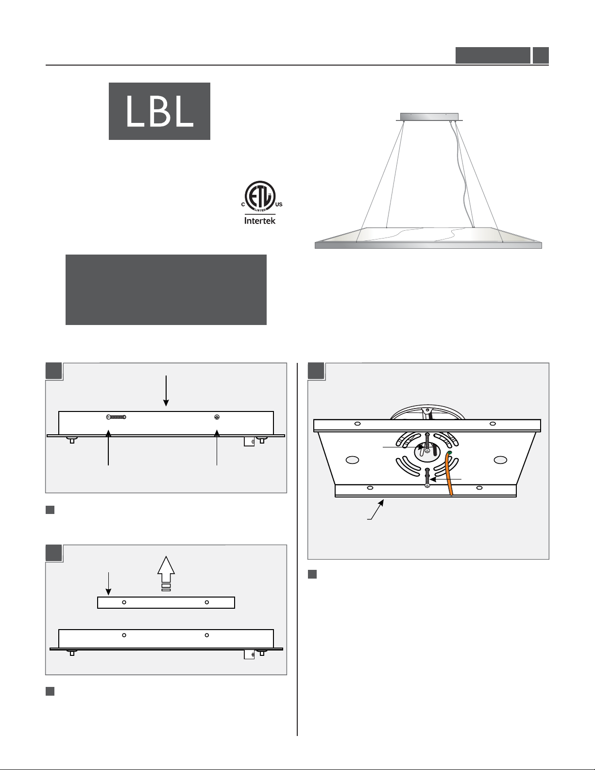
Install the Mounting Plate
1A
MOUNTING
PLATE SCREW
1
Separate the mounting plate from the canopy by
removing all four mounting plate screws.
1B
MOUNTING PLATE
CANOPY
MOUNTING
PLATE SCREW
1C
#8-32 SCREW
#8-32 SCREW
MOUNTING
PLATE
3
Secure the mounting plate to the electrical box with the
two #8-32 screws provided.
2
Remove the mounting plate from the canopy.
1
Page 2
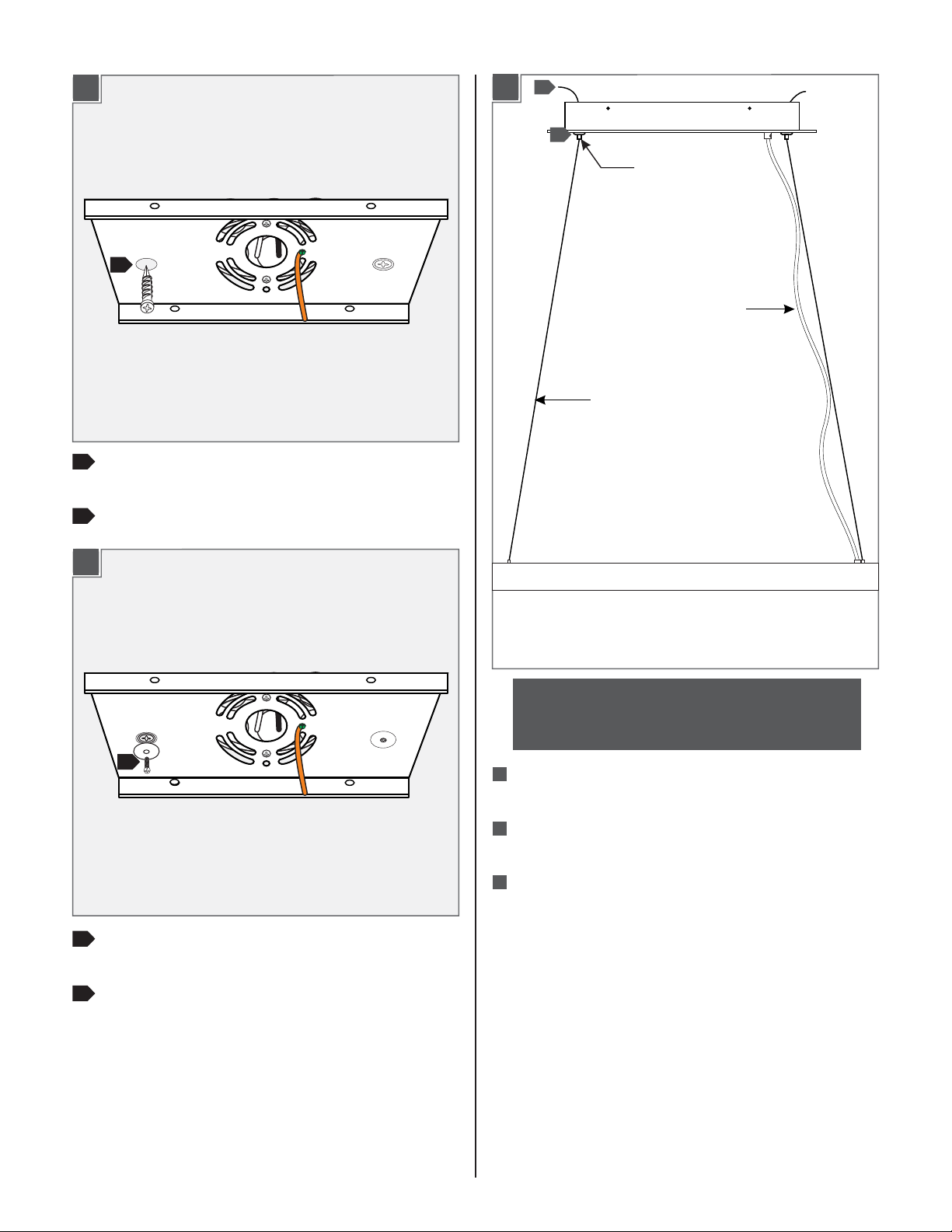
1C
4
4
Line up an anchor with the center of a backplate hole
and push the anchor in up to the threads.
Assemble the Fixture
3
2A
1
CABLE
CLUTCH
POWER
CORD
AIRCRAFT
CABLE
Screw the anchor the rest of the way in with a
5
screwdriver.
1C
6
Secure the backplate to the anchor with a screw and
6
washer.
NOTE: Make sure to support the fixture while
adjusting the aircraft cables. An assistant is
recommended to complete the remaining steps.
1
Feed the aircraft cables through the cable clutches in
the canopy.
2
Evenly pull the aircraft cable up through the canopy to
raise the fixture to the desired leveled length.
3
Cut off the excess aircraft cable leaving enough for fine
leveling later.
7
Repeat steps 4-6 for the remaining anchor hole.
7
2
Page 3
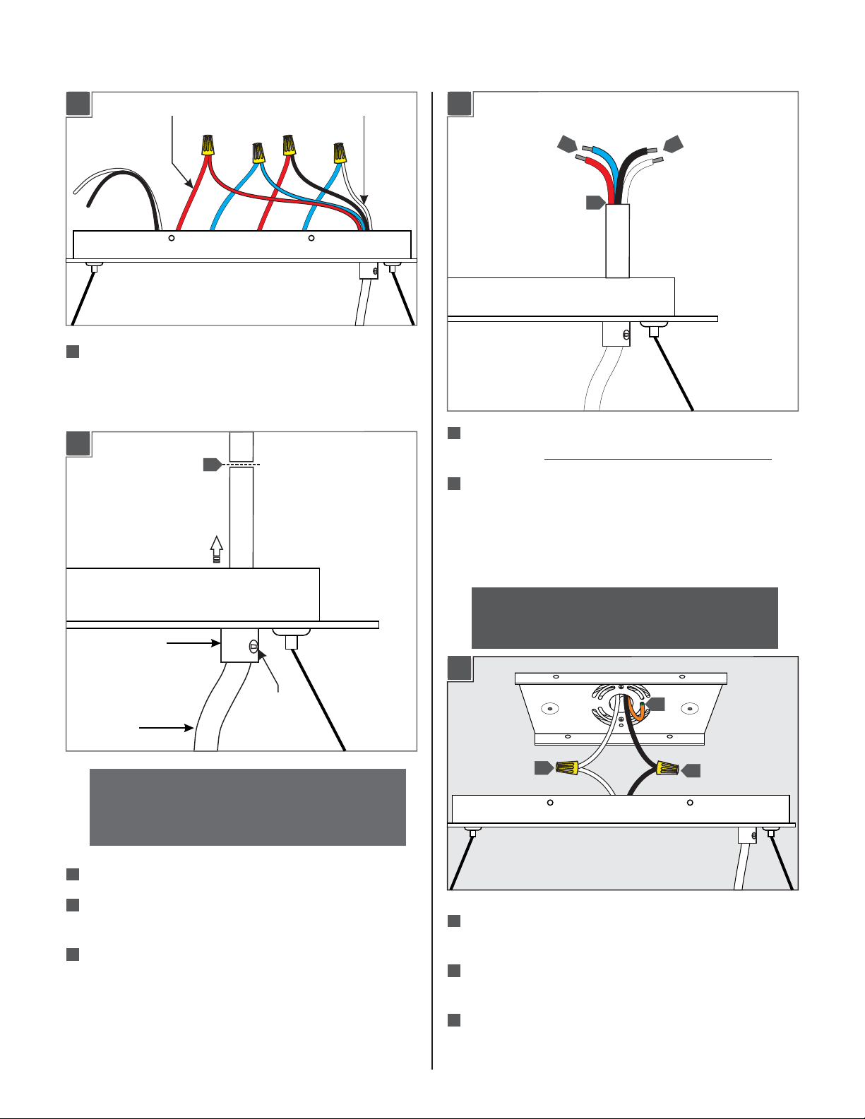
Adjust the Power Cord (optional)
3A
1
Take note of the wire connections and remove the wire
DRIVER WIRE
POWER CORD WIRE
nuts to disconnect the power cord wires from the driver
wires.
3B
4
3B
6
5
5
From the end of the cord, strip the insulation 4" using a
sharp knife. .Make sure not to nick the inner wires
6
Cut off the extra cord, strip 1/2" off the wire ends, and
reconnect the power cord wires to their original
connections (reversal of 3A).
6
STRAIN RELIEF
SET SCREW
POWER
CORD
NOTE: The power cord does not support the fixture.
For a casual “lazy cord” look, cut the power cord
several inches longer that the drop height of the
fixture.
2
Loosen the set screw in the strain relief.
3
Pull the power cord through the canopy until it reaches
the length desired and re-tighten the set screw.
4
Leave 6 inches of cord behind the canopy and cut off
extra cord.
Install the Fixture
NOTE: It is recommended that one person hold the
fixture while the electrician connects the power and
installs the canopy.
4A
1
2
1
Connect the fixture to a suitable ground in accordance
with local electrical codes.
2
Connect the white driver wire to the neutral power line
wire with a wire nut.
3
3
Connect the black driver wire to the hot power line wire
with a wire nut.
3
Page 4
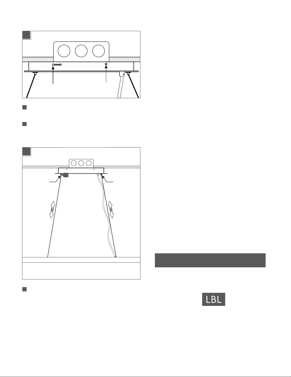
4B
MOUNTING
PLATE SCREW
4
Place the driver, all wires, and wire nut connections
MOUNTING
PLATE SCREW
inside the canopy.
5
Align the canopy holes with the mounting plate holes.
Secure the canopy in place by tightening the four
mounting plate screws.
4C
CABLE
CLUTCH
6
CABLE
CLUTCH
6
Adjust the aircraft cables until the fixture is level; feed
the cable into the cable clutch to raise the fixture and
push in on the cable clutch nipple to release the cable
and lower the fixture.
SAVETHESE INSTRUCTIONS!
7400 Linder Ave, Skokie, IL 60077
800.323.3226 - 847.626.6300
www.lbllighting.com
© 2014 LBL Lighting.All rights reserved. The "LBL Lighting" graphic is a
registered trademark of LBL Lighting. LBL Lighting reserves the right to
change specifications for product improvements without notification.
4
A Generation Brands Company
 Loading...