

Page 1
Installation Instructions for
980VENETSP
Veneto Suspension
Suspension
GP I :ENERAL RODUCT NFORMATION
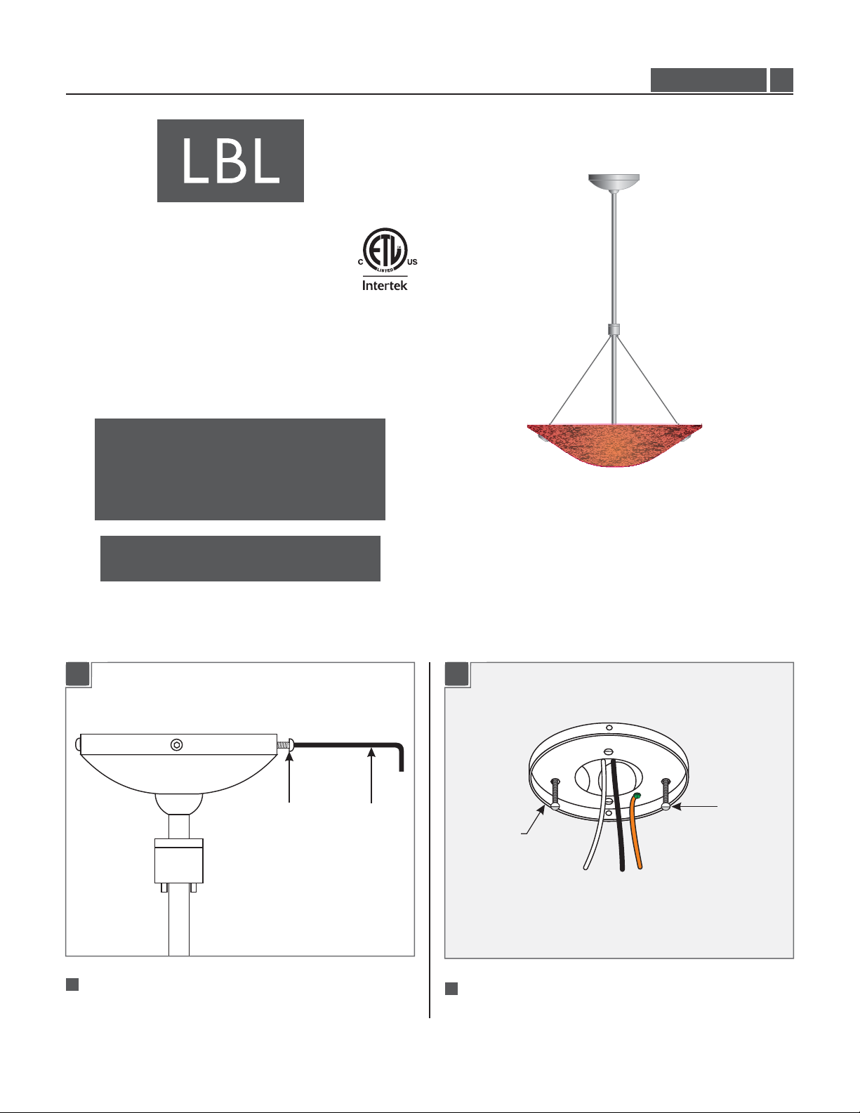
This product can mount to either a 4" square electrical box with
round plaster ring or an octagon electrical box.
This product is suitable for damp locations.
This product can be dimmed with a standard incandescent dimmer.
CAUTION - RISK OF FIRE
This product must be installed in accordance with
the applicable installation code by a person familiar
with the construction and operation of the product
and the hazards involved.
Use minimum 90°c supply conductors.
HS317_2J150
1.6
NOTE:This canopy may be installed to sloped
ceilings with .MAX 45° tilt
Install the Cross Bar
SCREW
ALLEN
WRENCH
1B1A
#8-32 SCREW
CROSSBAR
ASSEMBLY
11
Separate the crossbar from the canopy by removing all
four screws with the Allen wrench provided.
2
Mount the crossbar to the electrical box with the two
#8-32 screws provided.
1
Page 2
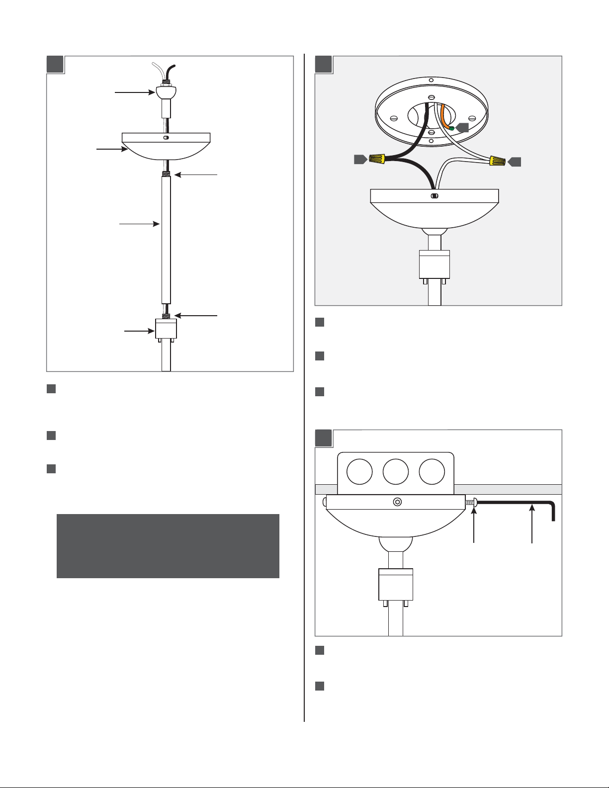
Adjust the Fixture Height (Optional)
HALF BALL PIVOT
CANOPY
THREADED NIPPLE
EXTENSION STEM
Install the Fixture
3A2A
2
1
3
THREADED NIPPLE
HUB
1
Temporarily remove the canopy and half ball pivot from the
assembly by unscrewing the pivot from the hub and pulling the
fixture wires through.
Feed the fixture wires through the optional extension stem(s)
2
and tighten completely to the threaded nipple on the hub.
Feed the fixture wires through the canopy and half ball pivot
3
and tighten completely to the threaded nipple on the new
extension stem.
NOTE:Use a 24" stem for the minimum 34" overall
height.To extend the fixture height to 46", or 58", or 70",
use the additional 12", or 24", or combination of 12" and
24" provided extension stems respectively.The extension
stems are not field cuttable.
1
Connect the fixture to a suitable ground in accordance
with local electrical codes.
2
Connect the black fixture wire to the hot power line wire
with a wire nut.
3
Connect the white fixture wire to the neutral power line
wire with a wire nut.
3B
SCREW
WRENCH
ALLEN
4
Place all wire and wire nut connections inside the
electrical box.
5
Align the canopy holes with the crossbar holes. Secure
the canopy in place by tightening the four screws with
the provided Allen wrench.
2
Page 3

Install the Lamp
Install the Glass
4A 5A
SOCKET
LAMP
SHIELD
CAUTION:To reduce the risk of a burn or electric shock
during relamping, disconnect the power to the fixture.
1
2
NOTE:Use only your fingers and a soft cloth to replace
the lamp.
AIRCRAFT CABLE
CABLE BUSHING
PLASTIC WASHER
PLASTIC WASHER
1
Remove the cap screw from the cable bushing.
2
Remove the knurled nut and one of the plastic washers from
2
KNURLED NUT
1
CAP SCREW
the cap screw.
5B
AIRCRAFT CABLE
Use Volt,
MAX 120 150 Watt
type E11mini candelabra base lamp.
1
Screw the lamp completely into the socket.
Push the lamp shield completely onto the spring clips.
2
CABLE CAP
KNURLED NUT
WHITE WASHER
CLEAR WASHER
3
From outside of the glass shade, insert the cap screw through
CAP SCREW
GLASS
one glass shade hole.
4
Place the second plastic washer onto the cap screw and finger
tighten the knurled nut to secure the cap screw in place.
5
Screw the cable bushing completely to the cap screw.
6
Repeat steps 1 through 5 for the remaining glass shade holes.
3
Page 4

IMPORTANT SAFETY INSTRUCTIONS
5C
HUB
AIRCRAFT
CABLE
GLASS
NOTE: Make sure to support the glass shade while
adjusting the aircraft cables. An assistant is
recommended to complete these steps.
7
Feed the aircraft cables through the cable clutches in
the hub.
8
Pull the aircraft cable up behind the hub to raise the
glass. Make sure that the glass is at least 3.5” away
from the lamp, but high enough to cover the lamp.
9
To lower the glass shade, push the cable clutch in and
pull the aircraft cable down.
CABLE
CLUTCH
To reduce the risk of fire, electrical shock, exposure to
excessive UV radiation, or injury to person:
– Use this fixture indoors only.
– Do not look directly at the lighted lamp.
– Do not remain in light if skin feels warm.
– Risk of fire: Use only the type of lamp and maximum wattage
indicated in this instruction manual.
– Never cover the halogen lamp with anything other than a LBL
Lighting lamp shield and never place flammable material close to
your fixture.
– Never turn the fixture on and off by connecting and
disconnecting the halogen lamp.
– Do not touch the fixture shades or lamp shield while the fixture
is on.These surfaces may be HOT.
Halogen Lamp General Information
– A new halogen lamp may smoke slightly when it is used for the
first time.This is perfectly normal; the protective coating is simply
being vaporized.
Two Tips For Prolonging Halogen
Lamp Life
– First avoid touching the lamp with bare hands during installation.
Any contaminant, even the oil from your hands can deteriorate
the lamp. Rubbing alcohol can be used to remove any
contaminant.
– Second, do not run the lamps at full power when you do not
need to. However, if dimming the fixture for an extended period
of time, occasionally bring the light up to full brightness for a few
minutes to complete the halogen cycle.
10
When the glass is in the desired position, trim the excess
aircraft cable behind the hub.
NOTE: To replace the lamps, simply reach the lamp
from top of the glass shade. The canopy is equipped
with a max 45 tilt capability which may assist in°
lamp replacement.
DO NOT REMOVE THE GLASS.
SAVETHESE INSTRUCTIONS!
7400 Linder Ave, Skokie, IL 60077
800.323.3226 - 847.626.6300
www.lbllighting.com
© 2014 LBL Lighting.All rights reserved. The "LBL Lighting" graphic is a
registered trademark of LBL Lighting. LBL Lighting reserves the right to
change specifications for product improvements without notification.
4
A Generation Brands Company
 Loading...