

Page 1
Installation Instructions for
980TWIL20CH
Twilight 12, 20
Chandeliers
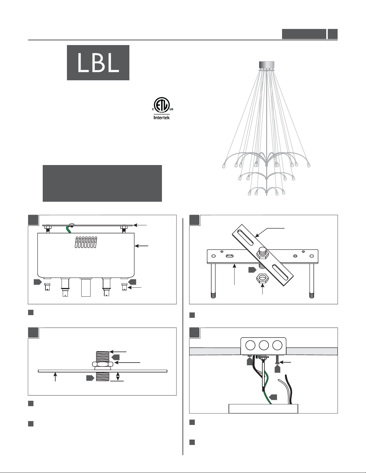
GP I :ENERAL RODUCT NFORMATION
This product can mount to either a 4" square electrical box with
round plaster ring or an octagon electrical box.
This product is suitable for indoor dry locations only.
This product can be dimmed with a low-voltage electronic dimmer.
CAUTION - RISK OF FIRE
This product requires installation by a qualified
electrician. Before installing be sure to read all
instructions and TURNTHE POWER TO THE
ELECTRICAL BOX OFF.
HS44_410_
1.1
Install the Canopy
1A
1 1
1
Remove the two cap nuts to lift the backplate out of the
canopy.
1B
THREADED NIPPLE
3
2
CROSSBAR
1/4"
BACKPLATE
CANOPY
CAP NUT
NUT
1C
CROSSBAR
4
BACKPLATE
NUT
4
Screw the crossbar assembly onto the backplate to form an
“X” and secure it to the backplate with a nut.
1D
5
6
#8-32 SCREW
6
2
Screw the threaded nipple onto the crossbar so that 1/8” to
1/4” is exposed on the other side of the crossbar.
3
Secure the threaded nipple in position by tightening the nut
against the crossbar.
5
5
Connect the fixture to a suitable ground in accordance with
local electrical codes.
6
Mount the crossbar assembly to the electrical box with two
#8-32 screws.
1
Page 2
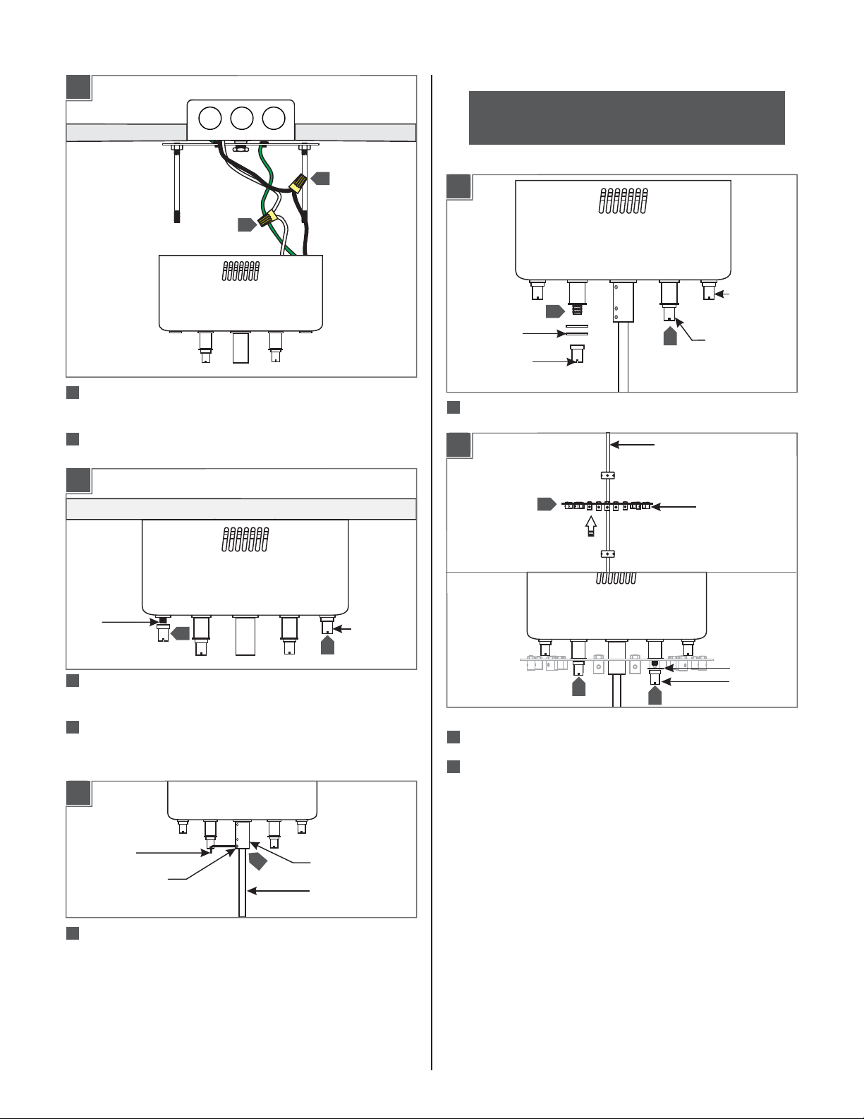
1E
5
7
8
7
Connect the canopy white wire to the neutral power line wire
with a wire nut.
8
Connect the canopy black wire to the hot power line wire
with a wire nut.
1F
NOTE:The 12 light version does not have a hub plate. If
installing a 12 light, skip to section 4.
Install the Hub Plate (20 Light Only)
2A
OUTER CAP
1
WASHER
CAP NUT
1
Remove the two inner cap nuts and washers.
2B
2
1
STEM
NUT
INNER CAP
NUT
HUB PLATE
THREADED
RODS
9
Place all wires and wire nut connections properly inside the
10
10
canopy housing.
10
Slide the canopy housing onto the backplate threaded rods and
secure it in place by tightening the two cap nuts completely to
the threaded rods.
1G
2MM ALLEN
WRENCH
M3 SET
SCREW
Push the stem completely into the canopy’s center power post,
11
and tighten the two bottom two M3 set screws with the
provided 2 MM Allen wrench.
To raise the chandelier height: Determine the desired
length of the stem, remove the stem from the power
post, and follow the instructions on the next page.
11
POWER POST
STEM
CAP NUTS
3
2
Slide the hub plate center hole completely onto the stem.
3
Align the hub plate holes with the inner power posts. Secure
3
CAP NUT
the hub plate in place by tightening the cap nuts and washer
completely to the power posts.
WASHER
2
Page 3
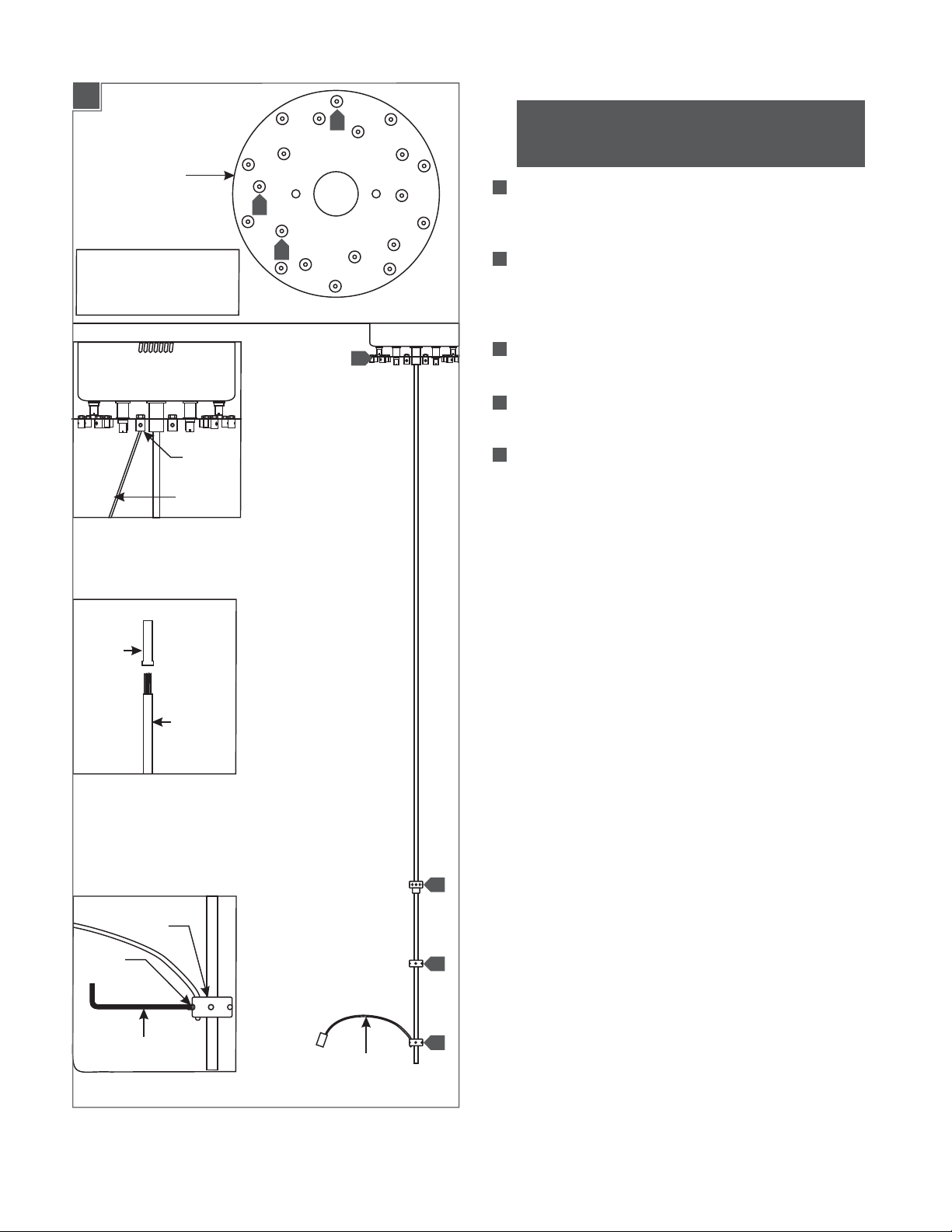
Install the Fixture Arms for 20 Light
3A
HUB PLATE
L = Long Socket Assembly Wire
M = Medium Socket Assembly Wire
S = Short Socket Assembly Wire
"L" POST
WIRE
ASSEMBLY
S
M
S
S
M
4
S
2
5
L
L
M
S
S
L
M
S
L
S
M
L
S
S
NOTE:This section is for the installation of the arms
for the 20 light version. Skip to the section 4 for the 12
light version.
1
Insert the arm of a long socket assembly into one of the
bottom hub holes and tighten the M3 set screw with the
provided 1.5 MM Allen wrench.
2
Feed the stripped portion of the long socket assembly wire
into the provided metal sleeve, and into the nearest "L" port
onto the hub plate. Tighten the M4 set screw with the 2 MM
Allen wrench.
3
2
Repeat steps 1 & 2 for the remaining four long socket assembly
wires.
Repeat steps 1 through 3, using the medium socket assembly
4
wires middle hub, and the "M" posts on the hub plate.
5
Repeat steps 1 through 3, using the short socket assembly wire
top hub and the "S" posts on the hub plate.
METAL
SLEEVE
M4 SET
SCREW
HUB
2MM ALLEN
WRENCH
WIRE
ASSEMBLY
5
4
3
ARM
3
Page 4

Shortening the Chandelier (Optional)
3B
CUT
HERE
A
Review the steps above for installing the fixture arms before
continuing.
B
Cut the stem down with an appropriate cutterfrom the top
(like a hacksaw),and deburr the cut end with a file or grinder.
C
Lay the stem on a flat surface. Attach a short socket arm to
the bottom hub, and pull the wire on the arm to the top end
of the stem. Cut the wire down to that length.
D
Remove the arm from the hub,and lay it next to the other
short arms. Measure and cut the remaining wires to the same
length and strip the last 1/4” of each wire.
E
Repeat steps A-D above for the medium-length arms on the
middle hub, and the long arms on the top hub.
F
Return to step 11 on the previous page and continue with the
installation.
3C
6
2 MM ALLEN
WRENCH
6
If necessary, loosen the set screw on the hub with an Allen
wrench to adjust the hub. Re-tighten the set screw after
adjustment.
M4 SET SCREW
4
Page 5

Install the Fixture Arms for 12 Light
4A
CANOPY
L = Long Socket Assembly Wire
S = Short Socket Assembly Wire
“L" POST
WIRE
ASSEMBLY
S
L
L
S
L
4
2
L
L
L
5
S
L
L
S
2
NOTE:This section is for the 12 light version only.
Insert the arm of a long socket assembly into one of the
1
bottom hub holes and tighten the M3 set screw with the
provided 1.5 MM Allen wrench.
Feed the stripped portion of the long socket assembly wire
2
into the provided metal sleeve, and into the nearest "L" port
onto the canopy. Tighten the M4 set screw with the 2 MM
Allen wrench.
3
Repeat steps 1 & 2 for the remaining eight long socket
assembly wires.
Repeat steps 1 through 3, using the short socket assembly wire
4
top hub and the "S" posts on the canopy.
METAL
SLEEVE
M4 SET
SCREW
HUB
2MM ALLEN
WRENCH
WIRE
ASSEMBLY
4
3
ARM
5
Page 6

Shortening the Chandelier (Optional)
4B
CUT
HERE
Review the steps above for installing the fixture arms before
A
continuing.
Cut the stem down with an appropriate cutterfrom the top
B
(like a hacksaw),and deburr the cut end with a file or grinder.
Lay the stem on a flat surface. Attach a short socket arm to
C
the bottom hub, and pull the wire on the arm to the top end
of the stem. Cut the wire down to that length.
Remove the arm from the hub,and lay it next to the other
D
short arms. Measure and cut the remaining wires to the same
length and strip the last 1/4” of each wire.
Repeat steps A-D above for the long-length arms on the
E
middle hub, and the long arms on the top hub.
4C
5
2 MM ALLEN
WRENCH
If necessary, loosen the set screw on the hub with an Allen
5
wrench to adjust the hub. Re-tighten the set screw after
adjustment.
M4 SET SCREW
6
Page 7

Install the Lamps & Glass Shade
Install the Flite paper (Optional)
5A
SOCKET
LAMP
1
NOTE:Use only your fingers and a soft cloth to install
the lamp.
Use Watt Bi-Pin Xenon (Xelogen)MAX 10
Lamp With Each Socket.
1
For each socket, push the lamp pins completely into the socket
holes.
5B
6A
CURVED SECTION
SLOT
SPRING CLIP
GLASS SHADE
2
2
Push the glass shade completely onto the spring clip.
Additional spring clips are available in the accessories bag.
1
Wrap the Flite Paper (if provided with the fixture) around the
lamp and insert the curved section into the slot and slide it to
lock it in place.
7
Page 8

SAVETHESE INSTRUCTIONS!
7400 Linder Ave, Skokie, IL 60077
800.323.3226 - 847.626.6300
www.lbllighting.com
© 2013 LBL Lighting.All rights reserved. The "LBL Lighting" graphic is a
registered trademark of LBL Lighting. LBL Lighting reserves the right to
change specifications for product improvements without notification.
8
A Generation Brands Company
 Loading...