

Page 1
Installation Instructions for
980TUBES7SP
Tubes Seven
Suspension
GP I :ENERAL RODUCT NFORMATION
This product is suitable for indoor dry locations only.
This product can be dimmed with a standard incandescent dimmer.
CAUTION - RISK OF FIRE
This product must be installed in accordance with
the applicable installation code by a person familiar
with the construction and operation of the product
and the hazards involved.
Use minimum 90°c supply conductors.
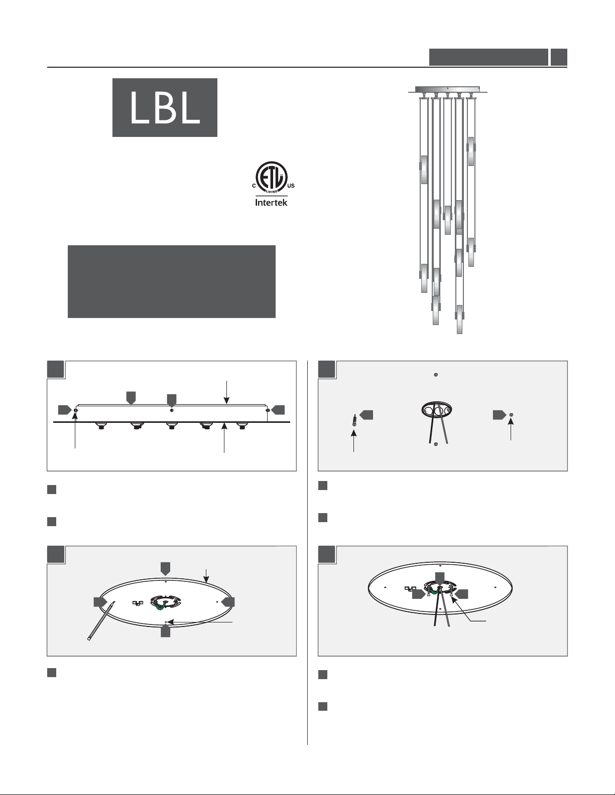
Install the Canopy
HS72932/1FR_1B35
1.0
1A
2
1
#8-32 SCREW
11
Remove the three #8-32 screws on the sides of the canopy
housing.
2
Lift the mounting plate out from the canopy housing.
MOUNTING PLATE
1
CANOPY HOUSING
1
1C
4
5
1B 1D
MOUNTING PLATE
3
3 3
MOUNTING
3
PLATE HOLE
4
ANCHOR
With a hammer tap the anchors at the marked points into the
ceiling up to the threaded portion.
Screw the anchors in the rest of the way with a Phillips
screwdriver.
6
7
7
77
5
ANCHOR
#8-32 SCREW
3
Align the mounting plate holes with the electrical box holes
and mark four points onto the ceiling through the mounting
holes.
6
Feed the power line wires through the mounting plate
center hole.
7
Line up the two mounting plate slots with the electrical box
holes and use the two provided #8-32 screws to mount it to
the electrical box.
1
Page 2
1E 1G
8
8
8
#8 SCREW
8
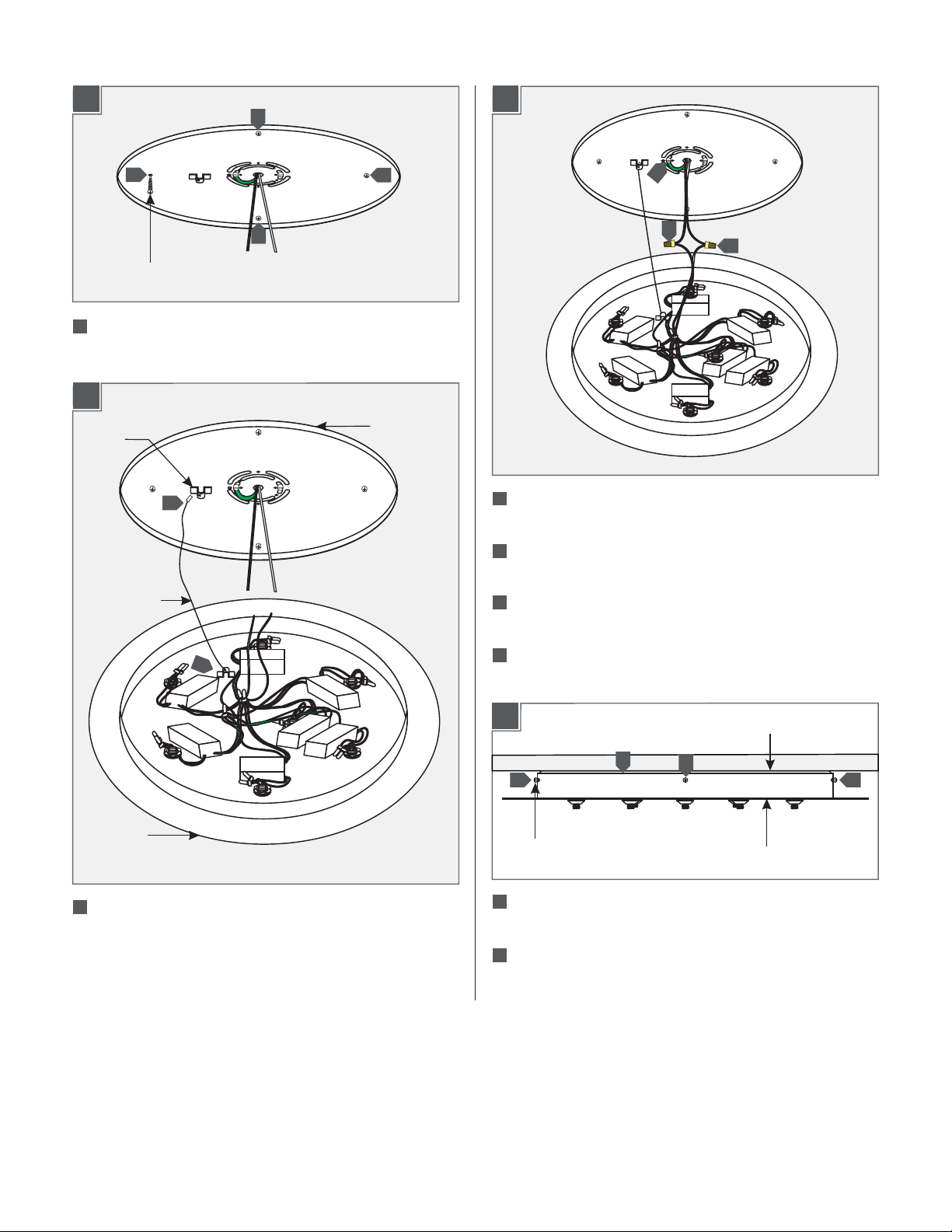
Secure the mounting plate to the anchors with the provided
#8 screws.
1F
MOUNTING
SAFETY
BRACKET
9
SAFETY CABLE
PLATE
8
10
Make sure the mounting plate is grounded in accordance with
10
12
11
local electrical codes.
11
Connect the housing white wire to the neutral power line wire
with a wire nut.
12
Connect the housing black wire to the hot power line wire
with a wire nut.
9
HOUSING
9
Insert one end of the safety cable into the mounting plate
safety bracket and insert the other end into the housing safety
bracket.
13
Place all wires and wire nut connections properly inside
the housing.
1H
14
15
#8-32 SCREW
14
Slide the housing onto the mounting plate and line up the
MOUNTING PLATE
15
CANOPY HOUSING
housing holes with the mounting plate holes.
Replace and tighten the three #8-32 screws to secure the
15
housing in place.
15
2
Page 3
Assembling the Fixture Arms
2A
(H)
(H1)
FIXTURE
FUSION
JACK
2B
M3 SET
2
2 2
2
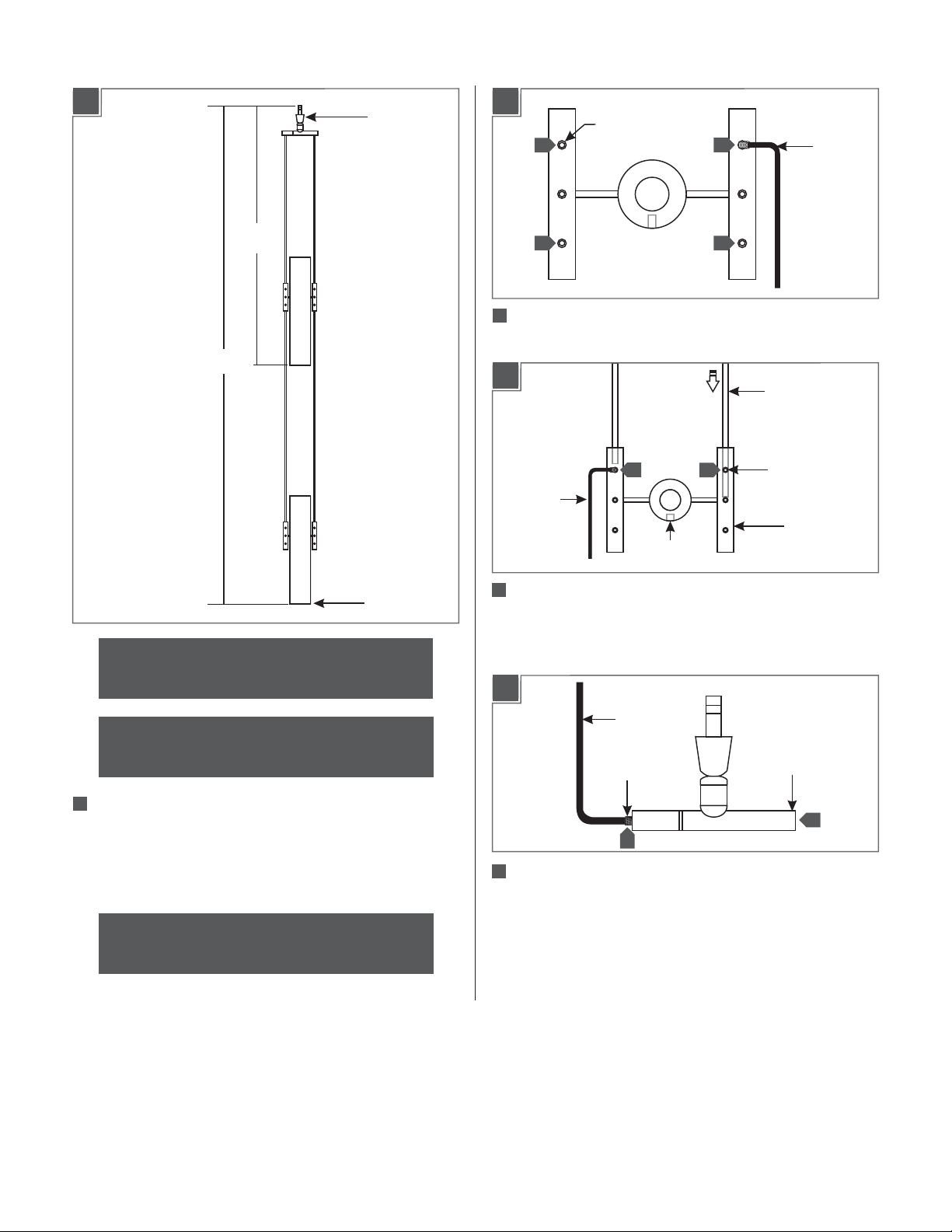
Loosen the four M3 set screws on the(Do Not Remove)
SCREW
socket assembly rods.
2C
1.5 MM ALLEN
WRENCH
3
SOCKET
PINHOLE
2
FIXTURE ROD
3
1.5 MM
ALLEN
WRENCH
M3 SET
SCREW
SOCKET
ASSEMBLY
ROD
GLASS SHADE
NOTE:Save the number on the packaging to later
install to canopy for proper orientation.
NOTE:The fixture arms vary in lengths follow
steps 1-13 for a typical installation.
11
The overall fixture height (H) is measured from bottom of the
bottom glass shade to the end of the fixture Fusion Jack.
Determine the overall desired fixture height.The height (H1) is
from the bottom of the top shade to the end of the fixture
Fusion Jack.
Optional: The Fixture Rods can be field cuttable to
a desired Height.
3
Insert the two fixture rods on the opposite side of socket pin
holes, completely into the socket assembly rod and secure into
place by tightening the M3 set screws with the provided
1.5 MM Allen wrench.
2D
1.5 MM ALLEN
WRENCH
FUSION JACK
M3 SET SCREW
4
4
Loosen the two M3 set screws on the(Do Not Remove)
sides of the Fusion Jack assembly rod with the provided
1.5 MM AllenWrench.
ASSEMBLY ROD
4
3
Page 4

2E
5
M3 SET SCREW
FUSION
JACK
ASSEMBLY
ROD
2G
FUSION JACK
ASSEMBLY ROD
5
1.5 MM ALLEN
WRENCH
M3 SET SCREW
7
FIXTURE ROD
7
Insert the fixture rods into the top Fusion Jack assembly rods,
1.5 MM ALLEN
WRENCH
and tighten the two M3 set screw with 1.5 MM Allen wrench.
FIXTURE ROD
5
Insert the fixture rods into the Fusion Jack assembly rod,make
sure the fixture rods are aligned with the top of the Fusion
Jack assembly rod.Tighten the two M3 set screw with 1.5 MM
Allen wrench.
2F
FIXTURE
FUSION
JACK
2I
M3 SET
8
8 8
8
Loosen the four M3 set screws on the(Do Not Remove)
SCREW
SOCKET PIN HOLE
middle socket assembly rods.
2J
8
1.5 MM
ALLEN
WRENCH
TOP FUSION JACK
ASSEMBLY ROD
TOP SOCKET
ASSEMBLY ROD
(H2)
6
The height (H2) is measured from bottom of the bottom glass
6
GLASS SHADE
shade to the middle of the top socket assembly rods.
Determine the desired (H2) fixture height.The height (H2) is
39" inches when the fixture rods are not cut.
FIXTURE ROD
9
9
9
Insert the Fusion Jack assembly rods from the end opposing
MIDDLE FUSION
JACK ASSEMBLY
ROD
the socket pin holes onto the fixture rods. Make sure that the
bottom Fusion Jack assembly rods are in line with the top
Fusion Jack assembly rods and tighten the two M3 set screws
with the 1.5 MM Allen wrench.
10
Repeat steps 1 through 9 to assemble the other fixture arms.
4
Page 5

Install the Lamp
3A
SOCKET
1
1
M3 SET
SCREW
NOTE:To reduce the risk of a burn or electric shock
during relamping, disconnect the power to the fixture.
1
For each socket, loosen the two M3 sets(Do Not Remove)
screw with the 1.5 MM Allen wrench.
1.5 MM ALLEN
WRENCH
3B
M3 SET
SCREW
2
LAMP
NOTE:Use only your fingers and soft cloth to replace
the lamp.
Use Watt,Type XelogenMAX 35
(Xenon) Bi-Pin Lamp,With Each Socket.
2
1.5 MM ALLEN
WRENCH
2
Push the lamp pins completely into the socket holes and
tighten the two M3 set screws with the 1.5 MM Allen wrench
to secure lamp in place.
WARNING: RISK OF FIRE
Never replace a Xenon (Xelogen) lamp with a regular
Halogen lamp.A regular Halogen lamp requires a protective
glass shield.
5
Page 6

Install the Lamp
3C
GLASS SHADE SLOT
4A
FUSION
JACK PORT
CANOPY
3
2
FUSION
JACK PORT
4
5
1
6
7
1
FIXTURE
FUSION
JACK
33
SOCKET ASSEMBLY
3
From between the fixture rods, carefully place a glass shade
onto each socket assembly.
Repeat steps 1 through 3 to install the lamp for the remaining
4
fixture arms.
CAUTION: load perRISK OF FIRE. Maximum
port is watt.75 Do Not Overload!
1
Starting with the center fusion jack port labeled 1 in the
canopy insert fixture arm labeled 1 by pushing and then
screwing the fixture arm Fusion Jack completely into the
Fusion Jack port and repeat for the following fixture arms.
6
Page 7

7
Page 8

SAVETHESE INSTRUCTIONS!
7400 Linder Ave, Skokie, IL 60077
800.323.3226 - 847.626.6300
www.lbllighting.com
© 2014 LBL Lighting.All rights reserved. The "LBL Lighting" graphic is a
registered trademark of LBL Lighting. LBL Lighting reserves the right to
change specifications for product improvements without notification.
8
A Generation Brands Company
 Loading...