

Page 1
Installation Instructions for
980TOPIIW
Top Wall II
Wall
GP I :ENERAL RODUCT NFORMATION
This product can mount to either a 4" square electrical box with
round plaster ring or an octagon electrical box.
This product is suitable for damp locations.
This product can be dimmed with a standard incandescent dimmer.
CAUTION - RISK OF FIRE
This product must be installed in accordance with
the applicable installation code by a person familiar
with the construction and operation of the product
and the hazards involved.
Use minimum 90°c supply conductors.
HW240_1B35
1.2
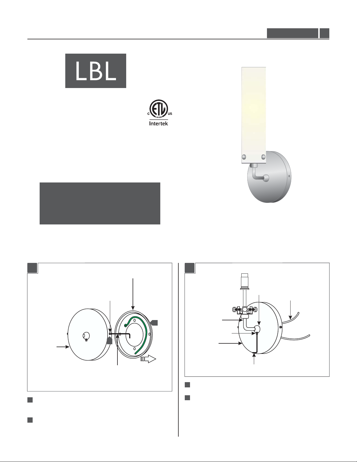
Install the Fixture
1A 1B
BACKPLATE
M3 SET SCREW
2
1
CANOPY
1.5MM ALLEN WRENCH
3
1
Loosen the two M3 set screws on side of(Do Not Remove)
the canopy with the 1.5MM Allen wrench provided.
Remove the backplate.
2
4
BUSHING
WIRES
SOCKET
ASSEMBLY ROD
M3 SET SCREW
CANOPY
1.5MM ALLEN WRENCH
Feed the socket assembly wires through the bushing.
Push the socket assembly rod completely into the bushing.
Level the socket assembly vertically and tighten the M3 set
screw with the 1.5 MM Allen wrench to hold the socket
assembly in place.
1
Page 2
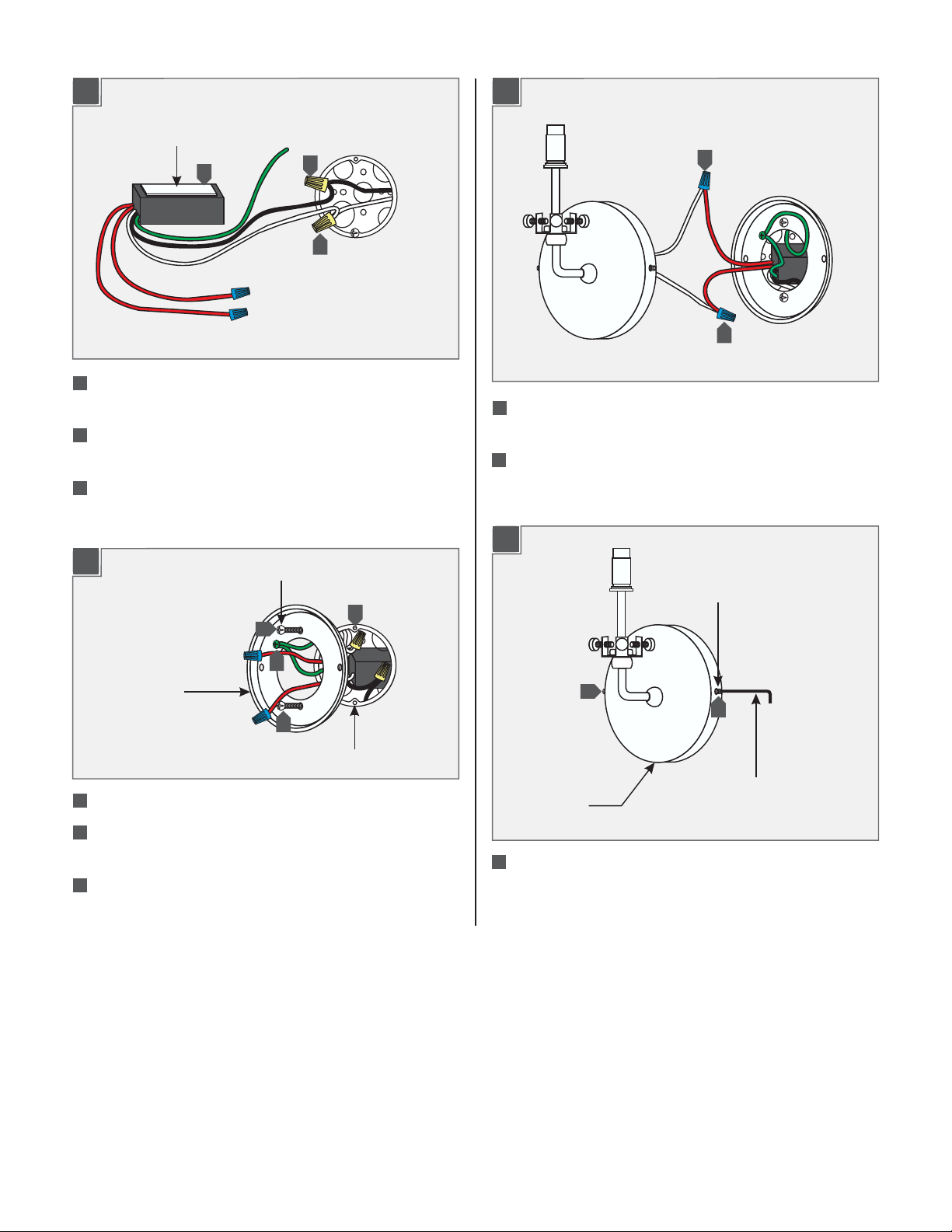
1C
STICKY PAD
7
5
Connect the transformer white wire to the neutral power line
wire with a wire nut.
6
Connect the transformer black wire to the hot power line
wire with a wire nut.
Place the transformer inside the electrical box. Use the
7
attached sticky pad to secure it against the electrical box.
1D
#8-32 SCREW
9
6
5
8
1E
11
11
11
Connect each transformer low voltage wire (red wire) to one
fixture wire with a wire nut.
12
Place all wires and wire nut connections inside the electrical
box.
1F
M3 SET SCREW
10
BACKPLATE
9
ELECTRICAL BOX HOLE
8
Line up two backplate holes with the electrical box holes.
9
Mount the backplate to the electrical box with the two #8-32
screws provided.
10
In accordance with local electrical codes, make sure that the
backplate and the transformer green wire are grounded.
13
13
1.5MM ALLEN WRENCH
CANOPY
13
Place the fixture canopy onto the backplate. Level the fixture
vertically and tighten the two M3 set screws with the 1.5MM
Allen wrench to secure the fixture in place.
2
Page 3

Install the Lamp
2A
LAMP
SOCKET
NOTE:Use only your fingers and a soft cloth to install
the lamp.
Use Watt Bi-Pin Xenon (Xelogen)MAX 35
Lamp.
1
2C
GLASS TUBE
SOCKET ASSEMBLY
BRACKET
THUMB SCREW
3
Carefully slide the glass tube ono the socket assembly.
NOTE:Omit the step 16 forTopWall II with opal glass.
1
Push the lamp pins completely into the socket holes.
WARNING: RISK OF FIRE
Never replace a Xenon (Xelogen) lamp with a regular
Halogen lamp.A regular Halogen lamp requires a protective
glass shield.
2B
2
THUMB
SCREW
2
2
2D
GLASS SHADE
4
BRACKET
THUMB SCREW
4
Align the glass holes with the bracket holes. Replace and
4
tighten the three thumb screws to secure the glass shade in
place.
4
2
Remove the three thumb screws.
NOTE:To replace the lamp:
- Turn the power to the fixture off.
- While supporting the glass shade, remove the three
thumb screws.
- Remove the tube glass.
- Remove the old lamp.
- Follow 2A through 2D.
3
Page 4

SAVETHESE INSTRUCTIONS!
7400 Linder Ave, Skokie, IL 60077
800.323.3226 - 847.626.6300
www.lbllighting.com
© 2014 LBL Lighting.All rights reserved. The "LBL Lighting" graphic is a
registered trademark of LBL Lighting. LBL Lighting reserves the right to
change specifications for product improvements without notification.
4
A Generation Brands Company
 Loading...