

LBL Lighting Standoff Ball Joint Assembly User Manual
Installation Instructions for
980MR2VTSP
Telescoping Rigid Standoffs with Ball Joint
2-Circuit Monorail
GP I :ENERAL RODUCT NFORMATION
This product is suitable for indoor dry locations only.
This product must be used with LBL Monorail system only.
This instruction is for the following models:
Monorail Support 2.5" - 4" (HANGER-ADJ-_1-2-BJ)
Monorail Support 6" - 10" (HANGER-ADJ-_2-2-BJ)
Monorail Support 12" - 24" (HANGER-ADJ-_3-2-BJ)
Monorail Support 24" - 48" (HANGER-ADJ-_4-2-BJ)
Monorail Support 48" - 96" (HANGER-ADJ-_5-2-BJ)
HANGER-ADJ-_-2-BJ
1.0
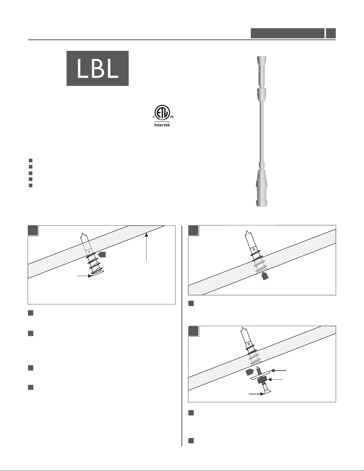
Installing the Standoff
1A
1A
4
CEILING
ANCHOR
1
Select a location on the sloped ceiling where the Monorail is to
be mounted.
One way of marking the standoff locations on the ceiling is to
2
lay the Monorail on the floor underneath of the selected
location and by using a plumb bob pointing on the center of
the Monorail mark the points on the sloped ceiling.
3
The other way is to hold the Monorail directly against the
sloped ceiling and mark the standoff points on the ceiling.
4
Tap the anchors at the marked points up to the threaded
portion with a hammer.
1B
1B
5
5
Screw the anchors in the rest of the way with a Phillips
screwdriver.
1B1C
6
#8 SCREW
WASHER
THREADED NIPPLE
6
Insert the #8 screw into the threaded nipple and washer.
Tighten the #8 screw completely into the anchor to secure the
washer and threaded nipple in place.
7
Repeat steps 4 through 6 for the remaining standoffs.
1
1A
1D
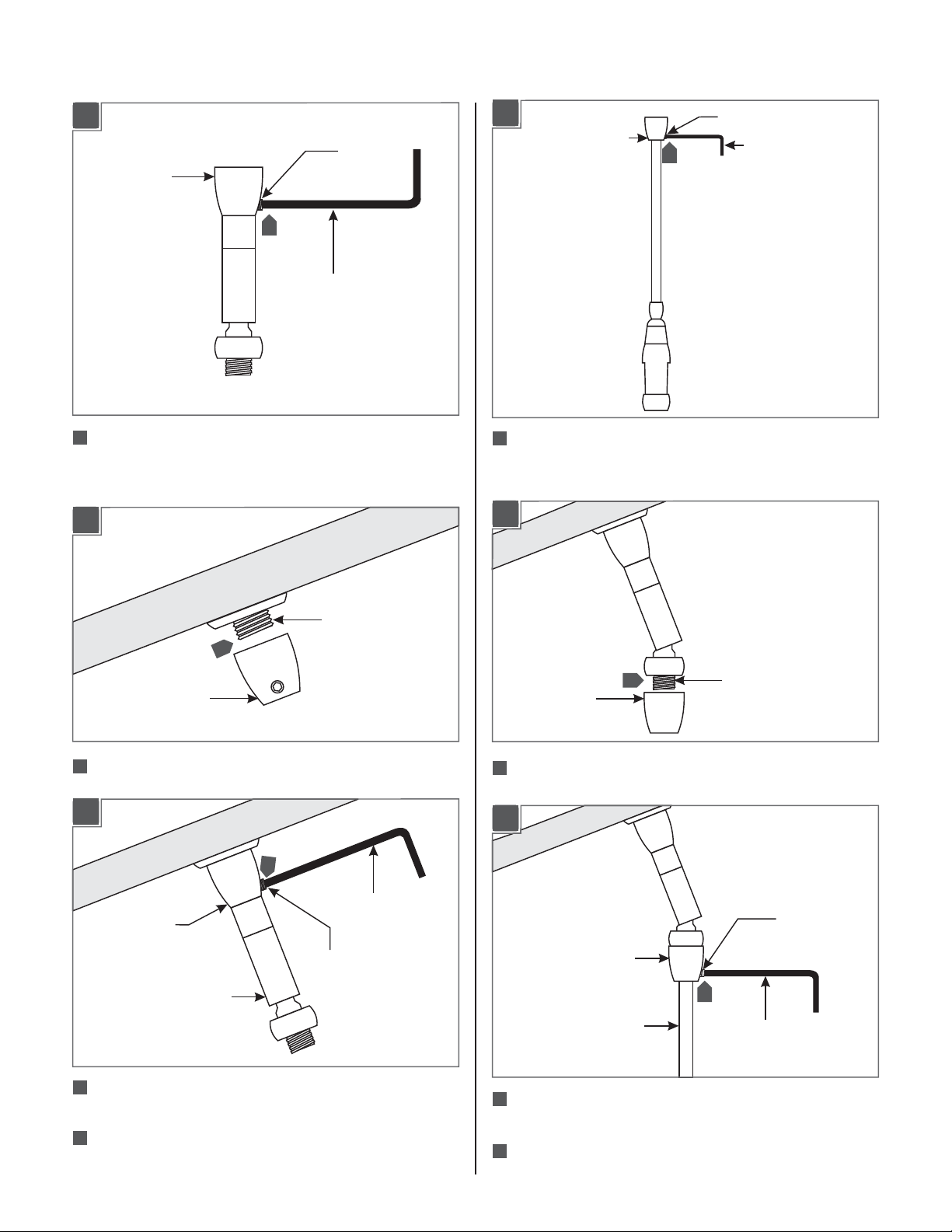
BALL JOINT POST
8
M4 SET
SCREW
2 MM ALLEN
WRENCH
1A1G
SUPPORT POST
12
M4 SET SCREW
2 MM ALLEN WRENCH
8
Loosen the M4 set screw on the ball joint(Do Not Remove)
post with the 2 MM Allen wrench provided and remove the
support post.
1A1E
THREADED NIPPLE
9
BALL JOINT POST
9
Screw the ball joint post completely to the threaded nipple.
1A1F
10
12
Loosen the M4 set screw on the support(Do Not Remove)
post with the 2 MM Allen wrench provided and remove the
support post.
1A1H
13
SUPPORT POST
Screw the support post completely onto the threaded post.
13
THREADED POST
1A1I
2 MM ALLEN
BALL JOINT POST
BALL JOINT ROD
10
Push the ball joint rod completely into the ball joint post and
WRENCH
M4 SET SCREW
tighten the M4 set screw with the 2 MM Allen wrench.
11
Repeat steps 8 through 10 for the remaining ball joint
connectors.
M4 SET SCREW
SUPPORT POST
14
STANDOFF ROD
14
Push the standoff rod completely into the support post and
2 MM ALLEN
WRENCH
tighten the M4 set screw with the 2 MM Allen wrench.
15
Repeat steps 12 through 14 for the remaining standoffs.
2
 Loading...